Kap 2.3-5V_120704_us..
Kap 2.3-5V_120704_us..
Kap 2.3-5V_120704_us..

You also want an ePaper? Increase the reach of your titles
YUMPU automatically turns print PDFs into web optimized ePapers that Google loves.
Hot Runner Nozzles<br />
5 V<br />
Chart for 5 V Hot Runner Nozzles<br />
Application Type Reference Cat. page<br />
Single nozzles<br />
E<br />
SER<br />
DER<br />
2.51<br />
Nozzles<br />
H<br />
SHR<br />
DHR<br />
2.53<br />
Example of nozzle specification on the reverse of this page.<br />
10/03<br />
Subject to technical changes.<br />
<strong>2.3</strong> _ <strong>5V</strong>-a
Hot Runner Nozzles<br />
5 V<br />
Example of a 5 V nozzle designation<br />
Order code:<br />
5 S H R 50 W H<br />
S<br />
S = Special construction<br />
(EVN-Code)<br />
Material tube<br />
diameter<br />
(depending on<br />
article weight +<br />
material)<br />
(see chapter 2)<br />
Nozzle<br />
with tip =<br />
Open<br />
Nozzle =<br />
S<br />
D<br />
W = Optimized temperature profile<br />
(with reduced material tube diameter<br />
for very small shot weights (0.05...2 g)<br />
in conjunction with thermally senitive<br />
material)<br />
Length of the nozzle (Measurement L)<br />
Operating voltage R = 5 V<br />
H =hard metal tip<br />
A = Type C only for open nozzle<br />
C = Type C only for open nozzle<br />
Type of nozzle<br />
E = Single nozzles<br />
H = Nozzles in conjunction<br />
<strong>2.3</strong> _ <strong>5V</strong>-b<br />
Subject to technical changes.<br />
10/03
Gate b<strong>us</strong>hing in the hot runner nozzles<br />
5 V<br />
Gate b<strong>us</strong>hing version A for open Nozzles<br />
See further technical information on the nozzle and nozzle installation page for the<br />
respective nozzle type.<br />
For the nozzle type:<br />
DER,<br />
DHR<br />
+0.02<br />
L<br />
Selection criteria:<br />
• injection on intermediate gate<br />
• direct injection of flat ABS products weighing<br />
more than 100g<br />
• <strong>us</strong>e for shear-sensitive materials<br />
6.3<br />
Note:<br />
6.3<br />
1)<br />
ØD<br />
5...10°<br />
1.2 -0.1<br />
1)<br />
The size of the gate diameter depends on the<br />
processing material and the part weight.<br />
You will find instructions for determining the gate<br />
diameter D in chapter 11 or please contact<br />
our technical support department.<br />
Gate b<strong>us</strong>hing version C for Nozzles with tip an open Nozzles<br />
See further technical information on the nozzle and installation page<br />
for the respective nozzle type.<br />
For the nozzle type:<br />
SER/DER<br />
SHR/DHR<br />
6.3<br />
+0.02<br />
L<br />
Selection criteria:<br />
• injection of small products made of POM<br />
copolymers (please consult our application<br />
engineering department before <strong>us</strong>ing)<br />
• for special applications in which<br />
a flow orientation is to be avoided<br />
and a gate vestige of 1-2 mm is tolerable<br />
(or more with GF material)<br />
6.3<br />
80°<br />
1)<br />
ØD<br />
1.2 -0.1<br />
1)<br />
Note:<br />
The size of the gate diameter depends on the<br />
processing material and the part weight.<br />
You will find instructions for determining the gate<br />
diameter D in chapter 11 or please contact<br />
our technical support department.<br />
<strong>2.3</strong> _ <strong>5V</strong>-d<br />
Subject to technical changes.<br />
Subject to technical changes.<br />
5/03
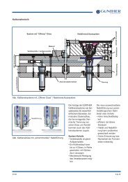
Installation of Hot Runner Nozzles<br />
5 V<br />
Hot Runner Nozzles<br />
5 V<br />
Single Nozzles Type 4SER, 5SER, 6SER/<br />
4DER, 5DER, 6DER<br />
Assembly with Gate B<strong>us</strong>hing (refer to chapter 3)<br />
L<br />
+0.02<br />
30 -0.02<br />
L +0.02<br />
5 +0.02<br />
1x45°<br />
22 -0.02<br />
5 +0.02<br />
1x45°<br />
Ø52<br />
Ø35.5<br />
2)<br />
ØS1<br />
5 V Nozzles with 5 V Manifold<br />
52<br />
ØS1 2)<br />
65<br />
26<br />
Locating ring<br />
(supplied by the c<strong>us</strong>tomer)<br />
Machine nozzle<br />
Adapter<br />
(Page 6.4)<br />
Use single nozzles only<br />
in conjunction with a<br />
machine nozzle adapter<br />
10<br />
5 V Manifold<br />
(Chapter 7)<br />
3)<br />
Cable channel<br />
20 5<br />
7.5<br />
1)<br />
2)<br />
3)<br />
Installation of gate b<strong>us</strong>hing<br />
6.3<br />
R2<br />
Notes:<br />
100°<br />
ØP<br />
H7<br />
H7<br />
ØT1<br />
+0.4<br />
ØS2<br />
R<br />
90°<br />
6.3<br />
1.6<br />
80°<br />
H7<br />
ØS<br />
6.3<br />
4)<br />
1.6 1.6 6.3<br />
1)<br />
ØD<br />
1.6<br />
45°<br />
<strong>2.3</strong><br />
1.2 -0.1<br />
L +0.02<br />
V -0.2<br />
4)<br />
min. t1<br />
The size of the gate diameter depends on the<br />
processing material and the part weight.<br />
You will find instructions for determining the<br />
gate diameter D in chapter 11 or please contact<br />
our technical support department.<br />
The diameter S1 is omitted when installing<br />
without gate b<strong>us</strong>h.<br />
L +0.02<br />
Further information on nozzles with tips and<br />
for open nozzles in the A and C versions can<br />
be found on the <strong>5V</strong>-d page.<br />
We recommend to lay the power and thermocouple<br />
cables in separate channels.<br />
A thermal damage of the thermocouple cables is<br />
therefore avoided.<br />
Single Nozzles Type 4SER, 5SER, 6SER /<br />
4DER, 5DER, 6DER<br />
Nozzle<br />
with tip<br />
Parting line<br />
Open<br />
nozzle<br />
Parting line<br />
L 0.5 L H C<br />
6.5<br />
W=30<br />
ØA<br />
ØB<br />
Ød<br />
ØA-0.05<br />
55°<br />
ØS<br />
ØS<br />
P<br />
P<br />
35<br />
CAD-Reference point<br />
Ø5<br />
52<br />
ca. 600<br />
Ø13<br />
93<br />
Ø3.5<br />
F<br />
14<br />
Type A:<br />
Ø = Not related to the gating<br />
diameter (ØD=1.5 mm)<br />
Type C:<br />
Ø = Related to the gating<br />
diameter (ØD)<br />
flexible cable<br />
G<br />
Plug 146<br />
(or extension plug<br />
142/L)<br />
Order Information:<br />
Example: a nozzle with tip or an open nozzle<br />
in conjunction with a manifold.<br />
Material tube diameter 4.8 mm,<br />
length 50 mm and<br />
Gating diameter 1.0 mm.<br />
Hot Runner Nozzle<br />
5SER50 (Type - nozzle with tip)<br />
5SER50H (Type H - with hard metal tip)<br />
5DDER50A (Type A - open nozzle)<br />
5DER50C-1.0 (Type C - open nozzle)<br />
Note:<br />
For very small shot weights (0.05 to 2 grams)<br />
and thermally sensitive materials (flame<br />
retardant), it is necessary to <strong>us</strong>e nozzles with an<br />
optimized temperature profile and a reduced<br />
material tube diameter.<br />
Example: 5SER50W<br />
5SER50WH (with hard metal tip)<br />
Note:<br />
The measurement L refers to the article surface,<br />
the nozzle expands by 0.5 mm in length<br />
at 250°C (325°F.)<br />
Note:<br />
In the case of small space availability an angle<br />
connector 147 can be <strong>us</strong>ed at the power<br />
connection.<br />
See chapter 8.<br />
Note:<br />
The fit between the nozzle / tool (ØS<br />
H7<br />
) or gate<br />
b<strong>us</strong>hing / tool (Ø T 1H7) has to be consistant<br />
throughout the whole length of the bore.<br />
For Technical Data:<br />
Refer to chapter11.<br />
Delivery in stock<br />
Semi-standard (short delivery time)<br />
Special production (delivery time given on request)<br />
Please Note:<br />
Dimension Ø H7> 10...18 =<br />
Nozzles<br />
with tip<br />
> 18...30 =<br />
> 30...50 =<br />
Open<br />
nozzles<br />
+0.018<br />
0<br />
+0.021<br />
0<br />
+0.025<br />
0<br />
ØP R ØS ØS1 ØS2 ØT1 V t1<br />
4SER 4DER 12 5 15 37 15.5 22 6.7 29<br />
5SER, 5SERW 5DER, 5DERW 12 5 18 39 18.5 26 8.2 28<br />
6SER, 6SERW 6DER, 6DERW 16 8 22 39 22.5 32 9 32<br />
4)<br />
If the nozzle length is 30 mm, the dimensions<br />
t1 and ØS2 are eliminated.<br />
For single nozzles, the locating ring and its<br />
screws m<strong>us</strong>t bear the load from the tool.<br />
Screws and locating rings have to be choosen<br />
careful and the circular pitch has to be as small<br />
as possible.<br />
For specifications see chapter 11.<br />
During assembly the nozzles m<strong>us</strong>t be fitted<br />
with a pre-load of 0.02 mm to 0.05 mm.<br />
Measurements and tolerances herein reference<br />
the tool. It is advisable to <strong>us</strong>e high temperature<br />
grease or spray on the outer surface of<br />
the nozzle barrel.<br />
Nozzles Open<br />
with tip nozzles<br />
4SER<br />
5SER<br />
6SER<br />
5SERW<br />
6SERW<br />
4DER<br />
5DER<br />
6DER<br />
5DERW<br />
6DERW<br />
Nozzle length L<br />
Ød ØA ØB C F G H P ØS 30 40 50 60 70 80 90 100120150180200<br />
4<br />
4.8 37.3 22<br />
6<br />
34.3 22<br />
37.3 24<br />
3.6 37.3 22<br />
4.8 37.3 24<br />
16<br />
16<br />
16<br />
16<br />
16<br />
5.5 10<br />
5.5 10<br />
5.5 10<br />
5.5 10<br />
5.5 10<br />
22<br />
22<br />
22<br />
22<br />
22<br />
19<br />
18<br />
21<br />
18<br />
21<br />
15<br />
18<br />
22<br />
18<br />
22<br />
<strong>2.3</strong> _ 4-6SER/DER Note: All dimensions are given in mm.<br />
Subject to technical changes. 2/04<br />
2/04<br />
Subject to technical changes.<br />
Note: All dimensions are given in mm.<br />
<strong>2.3</strong> _ 4-6SER/DER
Installation of the Hot Runner Nozzles<br />
5 V<br />
Hot Runner Nozzles<br />
5 V<br />
Hot Runner Nozzles Type 4SHR, 5SHR, 6SHR/<br />
4DHR, 5DHR, 6DHR<br />
Hot Runner Nozzles Type 4SHR, 5SHR, 6SHR/<br />
4DHR, 5DHR, 6DHR<br />
Assembly with Gate B<strong>us</strong>hing (refer to chapter 3)<br />
Manifold<br />
height<br />
Manifold<br />
height<br />
Installation without Gate B<strong>us</strong>hing<br />
12<br />
38 -0.02<br />
+0.02<br />
L<br />
12<br />
38 -0.02<br />
+0.02<br />
L<br />
2)<br />
Cable channel<br />
Nozzles<br />
with tip<br />
K<br />
+0.1<br />
5<br />
0.25x45°<br />
7.5<br />
K<br />
+0.02<br />
5<br />
1x45°<br />
0.5x45°<br />
20<br />
5<br />
32 32<br />
Open<br />
nozzles<br />
(20)<br />
105<br />
ØS3<br />
H7<br />
ØS1<br />
1.6<br />
3) See also notes<br />
40<br />
Clamp Plate<br />
Pressure pad<br />
817.250<br />
Manifold<br />
Cavity plate<br />
3) See also notes<br />
Clamp plate<br />
Pressure pad<br />
Manifold<br />
Manifold<br />
enclosure<br />
Cavity plate<br />
ØP R ØS ØS1 ØS2 ØS3 ØT1 V<br />
4SHR, 4SHRW 4DHR, 4DHRW 12 5 15 16 15.5 36 22 6.7 29<br />
5SHR, 5SHRW 5DHR, 5DHRW 12 5 18 19 18.5 39 26 8.2 28<br />
6SHR, 6SHRW 6DHR, 6DHRW 16 8 22 23 22.5 39 32 9.0 32<br />
t1<br />
1)<br />
2)<br />
6.3<br />
R2<br />
Notes:<br />
100°<br />
ØP<br />
H7<br />
H7<br />
ØT1<br />
We recommend to lay the power and thermocouple<br />
cables in separate channels.<br />
A thermal damage of the thermocouple cables is<br />
therefore avoided.<br />
For the expansion coefficient "K" see the<br />
manifold.<br />
Please note:<br />
1.6<br />
+0.4<br />
ØS2<br />
R<br />
90°<br />
80°<br />
H7<br />
ØS<br />
6.3<br />
4)<br />
6.3<br />
1.6 1.6<br />
1)<br />
ØD<br />
1.6<br />
45°<br />
<strong>2.3</strong> -0,1<br />
1.2 -0.1<br />
Dimensions Ø H7 > 10...18 =<br />
> 18...30 =<br />
> 30...50 =<br />
L +0.02<br />
V -0.2<br />
+0.018<br />
0<br />
+0.021<br />
0<br />
+0.025<br />
0<br />
4)<br />
min. t 1<br />
Further information on nozzles with tips and<br />
for open nozzles in the A and C versions can<br />
be found on the <strong>5V</strong>-d page.<br />
The size of the gate diameter depends on the<br />
processing material and the part weight.<br />
You will find instructions for determining the<br />
gate diameter D in chapter 11 or please contact<br />
our technical support department.<br />
3)<br />
The through hole in the clamping plate makes<br />
it possible to tighten the nozzle again after<br />
assembling the mould.<br />
4)<br />
If the nozzle length is 30 mm, the dimensions<br />
t1 and ØS2 are eliminated.<br />
L +0.02<br />
Measurements and tolerances herein reference<br />
the tool.<br />
It is advisable to <strong>us</strong>e high temperature grease or<br />
spray on the outer surface of the nozzle barrel.<br />
In conjunction with a manifold.<br />
Metal o-ring<br />
Nozzle<br />
with tip<br />
Parting line<br />
Open<br />
nozzle<br />
Parting line<br />
Ø32<br />
38<br />
L<br />
0.5<br />
L<br />
W=28<br />
6.2<br />
Nozzles Open<br />
with tip nozzles<br />
4SHR<br />
5SHR<br />
6SHR<br />
4SHRW<br />
5SHRW<br />
6SHRW<br />
4DHR<br />
5DHR<br />
6DHR<br />
4DHRW<br />
5DHRW<br />
6DHRW<br />
4.2<br />
3.5<br />
CAD-<br />
Reference<br />
point<br />
M4<br />
67.5°<br />
Ø37.9<br />
45°<br />
Ød<br />
ØS1<br />
55°<br />
ØS<br />
ØS<br />
P<br />
45°<br />
P<br />
Ø14<br />
52<br />
Ø34<br />
R3<br />
63<br />
Ø13<br />
Ø9<br />
Nozzle length L<br />
9.3<br />
Extension plug 142<br />
(or cable plug 146)<br />
21.7<br />
Flexible cable<br />
Thermo plug CMLK<br />
Ød P ØS ØS1 30 40 50 60 80 100120150180200250<br />
3.8<br />
4.8<br />
6<br />
2.5<br />
3.6<br />
4.8<br />
19<br />
18<br />
21<br />
19<br />
18<br />
21<br />
15<br />
18<br />
22<br />
15<br />
18<br />
22<br />
16<br />
19<br />
23<br />
16<br />
19<br />
23<br />
Type A:<br />
Ø = Not related to the gating<br />
diameter (ØD=1.5 mm)<br />
Type C:<br />
Ø = Related to the gating<br />
diameter (ØD)<br />
Order Information:<br />
Example: a nozzle with tip or an open nozzle<br />
in conjunction with a manifold.<br />
Material tube diameter 4.8 mm,<br />
length 50 mm and<br />
gating diameter 1.0 mm.<br />
Hot Runner Nozzle<br />
5SHR50 (Type - nozzle with tip)<br />
5SHR50H (Type H - with hard metal tip)<br />
5DHR50A (Type A - open nozzle)<br />
5DHR50C-1.0 (Type C - open nozzle)<br />
Order Instructions:<br />
Following parts have to be ordered separately<br />
1.Plug to the thermo b<strong>us</strong>hing<br />
Order No.: CMLK50 (incl. 0.5 m cable)<br />
CMLK100 (incl. 1 m Cable)<br />
CMLK150 (incl. 1.5 m cable)<br />
Examples of applications refer to chapter 8.<br />
Only as replacement<br />
1.Metal o-ring<br />
Order No.: 810.025 for 4SHR, 4DHR<br />
810.027 for 5SHR, 5DHR,<br />
6SHR, 6DHR<br />
2. Extension plug 142 or cable plug 146<br />
Examples of applications refer to chapter 10.<br />
Please note:<br />
For very small shot weights (0.5 to 2 grams) and<br />
thermally sensitive materials (flame retardant) it<br />
is necessary to <strong>us</strong>e nozzles with an optimized<br />
temperature profile and a reduced material tube<br />
diameter.<br />
z.B.: 5SHR50W<br />
5SHR50WH (with hard metal tip)<br />
The measurement L refers to the part surface,<br />
the nozzle expands by 0.5 mm at 250°C.<br />
Insallation guideline:<br />
The hot runner nozzles can be secured to the<br />
manifold in two ways:<br />
1. From the top of the manifold through the<br />
pressure pads (pitch circle Ø32) secured by<br />
two M4 bolts to the nozzle.<br />
2. From the bottom of the manifold secured<br />
by two M5 bolts adjacent to the groves R3<br />
on the nozzle.<br />
If flats (w = 28 mm)are cut into the nozzle<br />
then it can only be secured from the top of<br />
the manifold.<br />
Examples of applications refer to chapter 7.<br />
Technical Information:<br />
Please also see chapter 11.<br />
Delivery - in stock<br />
Semi-standard (short delivery time)<br />
Special production (delivery time upon request)<br />
<strong>2.3</strong> _ 4-6SHR/DHR<br />
Note: All dimensions are given in mm.<br />
Subject to technical changes.<br />
2/04 2/04 Subject to technical changes.<br />
Note: All dimensions are given in mm. <strong>2.3</strong> _ 4-6SHR/DHR