Hyper baric carburising process - Gruppo Italiano Frattura
Hyper baric carburising process - Gruppo Italiano Frattura
Hyper baric carburising process - Gruppo Italiano Frattura

You also want an ePaper? Increase the reach of your titles
YUMPU automatically turns print PDFs into web optimized ePapers that Google loves.
PROCESSI<br />
<strong>Hyper</strong> <strong>baric</strong> <strong>carburising</strong> <strong>process</strong><br />
E. Gianotti<br />
A new patented technology improves low pressure <strong>carburising</strong> in vacuum furnace and traditional<br />
<strong>carburising</strong> in sealed quench furnace.<br />
The author, starting from argument that is possible to see in the specialized publications on the subject,<br />
has examined by scientific criteria which are the limits and the advantages of both the low pressure<br />
<strong>carburising</strong> ,or the controlled atmosphere <strong>process</strong>. He evaluates the technological possibility to overcome<br />
some of the limits that are conditioning the mechanical property of the heat treated pieces. Before<br />
suggesting new technological solutions that can promote better metallurgical properties together with<br />
clean environment, he examine some scientific arguments to make clear the problems.<br />
At the end of this research some important technological modification will be realised and the obtained<br />
results confirm the validity of the new <strong>process</strong> of hyper <strong>baric</strong> carburisation.<br />
The cause of the defects arising from the traditional technology have been eliminated and the<br />
modifications requested on the furnaces are not expensive. In same cases, maybe the new furnaces are<br />
even cheaper, both in the buying phase than in the running cost.<br />
Memorie<br />
Key words: steel, <strong>carburising</strong>, heat treatment, plants and fixture<br />
INTRODUCTION<br />
The low pressure <strong>carburising</strong> has already reached a good<br />
diffusion in the heat treatment market .<br />
Compared with the old traditional controlled <strong>carburising</strong> atmosphere,<br />
it has the big advantages of being near pollution<br />
free.<br />
Some other advantages claimed by vacuum furnace builders<br />
have some difficulty being demonstrated by practical application,<br />
as it’s possible to see in the specialized publications<br />
on the subject.<br />
Avoiding taking into consideration some less technical arguments<br />
like cost effectiveness, speed of carbon penetration,<br />
and furnace and facility cost , the most stimulating discussions<br />
are about the technological property of the product,<br />
compared with the others obtained with the old controlled<br />
atmosphere.<br />
The most discussed arguments are the fatigue strength and<br />
the toughness that are conditioned by:<br />
- Surface decreasing of alloying elements.<br />
- Inter granular oxidation.<br />
- Speed of cooling in the quench step, using gas or gas mixture<br />
up to 20 bars.<br />
You can read about this subject in the bibliography at the<br />
end of this work 1) , 2) , 3).<br />
Starting from this argument, the author has examined, by<br />
scientific criteria, which are the limits and the advantages of<br />
both the low pressure <strong>carburising</strong> ,or the controlled atmosphere<br />
<strong>process</strong>. He evaluates the technological possibility to<br />
overcome some of the limits that are conditioning the mechanical<br />
property of the heat treated pieces.<br />
Before suggesting new technological solutions that can promote<br />
better metallurgical properties together with clean environment,<br />
we need to examine some scientific arguments to<br />
make clear the problems.<br />
a) Solid-gas phases equilibrium of the metals to high temperature.<br />
b) Thermodynamic equilibrium of the surface inter granular<br />
oxidation that can happen during the carburisation with<br />
Elio Gianotti<br />
Trattamenti Termici Ferioli & Gianotti SpA - Rivoli Torino Italy<br />
endogas or in the vacuum furnace if there are too many<br />
vacuum leaks.<br />
c) The quenching in gas, when the heat treatment is made in<br />
vacuum furnace, is too slow, also if it’s made with high<br />
pressure or blending of same expensive gas like He. In<br />
this case the toughness is lower than the quenching in oil.<br />
(See the bibliography 3) by Fernando Da Costan just<br />
quoted).<br />
SOLID-GAS PHASES EQUILIBRIUM OF THE METALS<br />
IN FURNACE TO HIGH TEMPERATURE<br />
Metals evaporation in vacuum furnace<br />
Every metal has a tension, or pressure of evaporation, that is<br />
only temperature dependent (see tab 1.)<br />
In an imaginary vacuum furnace, without leakage, if the absolute<br />
pressure that can reach the vacuum pump is lower<br />
than the evaporation tension of the metal, the metal evaporates<br />
continuously and goes to solidify on the cold walls of the<br />
furnace or of the pump that have a temperature lower than<br />
the metal evaporation. The remaining part of the vapour is<br />
eliminated by the pump.<br />
The metal that solidifies on cold walls decreases the partial<br />
pressure in the furnace, so other metal can evaporate.<br />
In the event where the absolute pressure generated by the<br />
pump is not lower than the metal evaporation tension, the<br />
metal vapour , also if it has saturated the furnace chamber ,<br />
cannot be extracted by the vacuum pump. It can also, in this<br />
event, solidify on the cold walls if these are at the temperature<br />
lower than the solid-gas equilibrium and allows further<br />
evaporation of the metal surface.<br />
In the more realistic event in which the furnace has some<br />
leakage, and if the vacuum pump is not able to reach value<br />
lower than metal evaporation pressure, some metal vapour<br />
can be sucked together with the air from the leakage,<br />
breaking the equilibrium of the ‘solid metal – vapour ’ and<br />
permitting again the evaporation of the metal surface.<br />
Therefore, in every event, the heating of the steel in the vacuum<br />
furnace generates a continuous loss of alloying elements<br />
from the surface. Only in the purely theoretical event<br />
of a vacuum furnace without leakage, with the inner walls at<br />
the same working temperature of the furnace and the vacuum<br />
pump isolated, would it be possible to avoid continuous<br />
evaporation of the alloying elements.<br />
7-8/2006<br />
la metallurgia italiana 41
PROCESSI<br />
7-8/2006 Memorie<br />
Metals evaporation in controlled atmosphere furnace<br />
Also in this furnace, the metal’s vapour tension generates an<br />
impoverishment on the steel’s surface that is more important<br />
as the temperature goes higher. The impoverishment will be<br />
higher in the alloying metals that have a higher tension (see<br />
table 1), so the surface composition can vary in its alloying<br />
elements.<br />
The impoverishment in this event is linked to the passage of<br />
<strong>carburising</strong> gas over the pieces’ surface.<br />
It’s not easy to say which of the two furnaces is more reliable<br />
regarding this problem, because many variables are to<br />
be considered.<br />
The vacuum furnace, with a good seal, surely has a lower<br />
number of atmosphere changes compared with the atmosphere<br />
competitor, but it has a great surface of cold walls<br />
that makes easy the vapour deposition of the alloying metals<br />
and can generate other evaporation.<br />
To avoid evaporation loss of alloying metals, considering<br />
that it is not possible to change the evaporation equilibrium,<br />
it’s only possible to decrease the atmosphere change in the<br />
furnaces and to maintain the walls’ temperatures near the<br />
<strong>process</strong> temperature.<br />
Utilizing low pressure carburisation by a vacuum furnace,<br />
the <strong>process</strong> temperature can arrive up to 1.000° C . At this<br />
temperature the Mn is the metal that has the highest vapour<br />
tension, followed in decreasing order by Al, Cu, Cr. It may<br />
be considered that the Mn vapour tension at 1.000°C is<br />
about 10 -2 mbar, while the absolute pressure at the furnace<br />
during the <strong>carburising</strong> <strong>process</strong> is about 10-30 mbar, so the<br />
vacuum is not too dangerous.<br />
Table 1 – Vapour tension of<br />
metals in the range 0° to<br />
2800°C.<br />
Tabella 1 – Tensione di<br />
vapore dei metalli a<br />
temperature da 0 a 2800°C.<br />
To better value the dangerous effect of the evaporation of alloying<br />
elements in vacuum furnace and particularly in the<br />
low pressure <strong>carburising</strong> <strong>process</strong>, see in the bibliography the<br />
work of B.Clausen 1) and Y. Bienvenu, K Vieillevigne 2).<br />
THERMODYNAMIC EQUILIBRIUM<br />
OF INTER GRANULAR OXIDATION<br />
Carburising <strong>process</strong> in controlled atmosphere<br />
The most utilized atmospheres are the endogas and the nitrogen-methanol<br />
. In both cases the blend of the gas is formed<br />
by about 20% of CO that is the most important in the<br />
exchange of the C from the atmosphere to the surface of the<br />
<strong>carburising</strong> steel.<br />
The schematic reaction is the following:<br />
2CO ↔ 2C + O 2<br />
.<br />
The free energy ∆ G of the reaction at 927° C (1200 K) calculated<br />
by the Barin Knacke parameter is<br />
2CO ↔ 2C + O 2<br />
with ∆ G = + 104149 Kcal at 927°.<br />
The constant K of the reaction will be:<br />
lnK = - 104.149 / (1,987 · 1200) = - 43,68 so K = e - 43,68<br />
but K = p (O 2<br />
) / p (CO 2<br />
) 2 than substituting the values will be:<br />
p (O 2<br />
) = e - 43,68 · 0, 2 2 = 4,3 -21 = 10 -20,37<br />
This value of p (O 2<br />
) generates about 1.140 mVolt in the<br />
oxygen probe (see Nerst formula) and is equivalent to a car-<br />
42<br />
la metallurgia italiana
PROCESSI<br />
bon potential of about 0,80% (see oxygen probes tables).<br />
It is so demonstrated that in the <strong>carburising</strong> atmosphere there<br />
is a pO 2<br />
equal to near 10 -20 and thereafter every element<br />
that is in such atmosphere, with a chemical equilibrium with<br />
the oxygen partial pressure equal or lower , will become an<br />
oxide.<br />
In table 2 there are some alloying elements that are always<br />
in the steel, also like impurity, with the relative partial oxygen<br />
pressure in equilibrium at 900°C with the element in the<br />
oxidising chemical reaction.<br />
Note as the metals Cr, Mn, Si, Al, normally present in the inter<br />
granular oxidation, oxidise with pO 2<br />
from 10 -24 to 10 -36 .<br />
To avoid their oxidation, it is necessary to operate with pO 2<br />
below 10 -36 .<br />
For more detailed information about the inter granular oxidation<br />
in the atmosphere controlled furnace, see ref.4).<br />
Low pressure <strong>carburising</strong> <strong>process</strong> in vacuum furnace<br />
Both in the low pressure <strong>carburising</strong> <strong>process</strong> or in plasma<br />
<strong>carburising</strong> <strong>process</strong> ( ionic discharge), the working pressure<br />
in the furnaces are about 10 – 200 mbar.<br />
Also, when the <strong>process</strong> is starting and there is the need to<br />
clean the chamber and the pieces, the higher vacuum reached<br />
by the pump is 10 -4 – 10 -5 bar; that is a vacuum very far<br />
from the 10 -36 /0.21 bar necessary to avoid the inter crystalline<br />
oxidation.<br />
The purity of the furnace is not sufficient, but the continuous<br />
introduction of high purity <strong>carburising</strong> gas, as N 2<br />
, Ar 2<br />
or hydrocarbon<br />
like C 3<br />
H 8<br />
, CH 4<br />
, C 2<br />
H 2<br />
or other, washes the atmosphere<br />
until it arrives at the needed purity.<br />
Normally, with furnaces with good sealing , it is possible to<br />
arrive at the end of the <strong>process</strong>, avoiding inter granular oxidation.<br />
The furnace sealing may deteriorate if the maintenance is<br />
not good. In this event, if the furnace absorbs air from the<br />
leakages, the oxygen concentration may increase over 10 -36 ,<br />
and the inter crystalline oxidation occurs.<br />
STIRRING OF CARBURISING ATMOSPHERE<br />
While in the controlled atmosphere furnace it is possible to<br />
homogenize easily the atmosphere composition in the inner<br />
furnace by one or more fans, it is more difficult to avoid<br />
stratifications or non uniformity in the vacuum furnace.<br />
There are some systems realized, the most curious has been<br />
made up by an important furnace builder in U.S. He has<br />
mounted a big fan in the furnace chamber.<br />
The non uniformity in the atmosphere may generate hardness<br />
and case depth problems.<br />
Réactions P(O 2<br />
) [bar] ∆G [Kcal]<br />
2Fe + O 2<br />
⇔ 2FeO 10 -16,7 -88<br />
4/3 Cr + O 2<br />
⇔ 2/3Cr 2<br />
O 3<br />
10 -24 -130<br />
2Mn + O 2<br />
⇔ 2MnO 10 -27 -145<br />
Si + O 2<br />
⇔ SiO 2<br />
10 -30 -160<br />
4/3 Al + O 2<br />
⇔ 2/3 Al 2<br />
O 3<br />
10 -36 -200<br />
2Mg + O 2<br />
⇔ 2MgO 10 -44 -230<br />
2H 2<br />
+ O 2<br />
⇔ 2H 2<br />
O 10 -17 -90<br />
2CO + O 2<br />
⇔ 2CO 2<br />
10 -16 -87<br />
Table 2 – Partial pressure p(O 2<br />
) in equilibrium at 900°C with the<br />
metals oxide and the CO and H 2<br />
.<br />
Data obtained from Ellingham-Richardson diagram.<br />
Tabella 2 – Equilibrio a 900°C della p(O 2<br />
) con gli ossidi dei<br />
metalli elencati e con l’idrogeno e il CO.<br />
Valori ricavati dal diagramma di Ellingham-Richardson.<br />
THE NEW HYPER BARIC TECHNOLOGY ELABORATION<br />
After we have seen all the advantages and the lacks of the<br />
old technologies, it is possible to engineer a new technology<br />
that takes into account only the advantages and eliminates<br />
the defects.<br />
In the low pressure carburisation, the problems are:<br />
a) Evaporations of alloying elements determined by low<br />
pressure and cold walls<br />
b) Few homogeneity of carburisation in the different zone of<br />
the furnace.<br />
c) Not satisfactory toughness due to slow cooling in the gas<br />
quenching .<br />
In the controlled atmosphere carburisation the problems are:<br />
d) Environmental, because of the pollution of atmosphere<br />
gas and quenching oil<br />
e) Inter crystalline oxidation with case depth proportional to<br />
square root of time, due to O2 existing in the endogas.<br />
f) Evaporations of alloying elements determined by <strong>carburising</strong><br />
atmosphere exchange.<br />
Vacuum furnace modifications<br />
It’s possible to avoid the a) and b) defects by modifying the<br />
furnace so that it can work above the atmospheric pressure.<br />
The cold wall will be thermally insulated using ceramic fibre<br />
or other light insulating materials and inner this insulation<br />
will be placed a strong, atmosphere tight crucible that<br />
also has the task of sustaining the <strong>carburising</strong> load.<br />
It will be necessary to change the instruments for the vacuum<br />
regulation by instruments suitable for regulation of<br />
overpressure.<br />
The vacuum pump may be eliminated otherwise, if existing<br />
may be utilised to clean more rapidly the furnace atmosphere.<br />
After five or more atmosphere changes by cryogenic nitrogen,<br />
with purity of 5 ppm O 2<br />
, the furnace will be held in light<br />
pressure , normally 500 mm of water. This way, it will<br />
avoid air entrance by possible leakage.<br />
The <strong>carburising</strong> atmosphere must be agitated by a fan to<br />
guarantee the carburisation homogeneity.<br />
To avoid the problem c) about the insufficient toughness, the<br />
unique solution is the oil quenching, so it is necessary to<br />
make provisions for an oil tank below the atmosphere quenching<br />
chamber. This is particularly useful for the commercial<br />
heat treatments that sometimes have many chemical<br />
steel compositions in the same load.<br />
Atmosphere furnace modifications<br />
The furnace must be modified with an addition in the inner<br />
part of a strong, atmosphere tight, crucible that has also the<br />
task of sustaining the <strong>carburising</strong> load, both in heating<br />
chamber or in the quenching zone. Also, the over pressure<br />
security valve must be gas tight.<br />
After this modification, the furnace can work as described in a<br />
vacuum modified furnace, with a tight nitrogen atmosphere.<br />
This is the condition to avoid the problem scheduled in d) and<br />
f), determined by the flow of the endothermic atmosphere.<br />
ELIMINATION OF INTER CRYSTALLINE OXIDATION<br />
Examining tab. 2, it is possible to note that for avoiding the<br />
alloying element oxidation, that is the origin of the inter granular<br />
oxidation, it is necessary to keep the oxygen partial<br />
pressure below 10 -36 .<br />
With the modification made with respect to the traditional<br />
furnaces , both vacuum or traditional controlled atmosphere<br />
, it is possible to arrive at a sealed chamber, delimitated by a<br />
crucible made in refractory steel, with leakage almost inexistent<br />
and at worst with the gas that goes out and not with the<br />
air that enters to damage the <strong>carburising</strong> atmosphere.<br />
Memorie<br />
7-8/2006<br />
la metallurgia italiana 43
PROCESSI<br />
7-8/2006 Memorie<br />
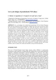
Fig. 1 – <strong>Hyper</strong> <strong>baric</strong> sealed<br />
quench furnace featured with<br />
the most important<br />
modifications compared to<br />
vacuum or controlled<br />
atmosphere furnace.<br />
1) Water cooled sealing<br />
gasket in the outer door.<br />
2) Over pressure bleeder with<br />
sealing, temperature resistant.<br />
3) Stirring fan for <strong>carburising</strong><br />
atmosphere.<br />
4) Quenching chamber with<br />
oil or pressurized gas.<br />
5) Computerized control of<br />
nitrogen during the cleaning ,<br />
the <strong>carburising</strong>, and the<br />
quenching time.<br />
6) Inner door.<br />
7) Carburising computerized<br />
control, according to the<br />
boost-diffusion cycle, with<br />
hydrocarbon like propane,<br />
cyclohexane alcohol.<br />
Fig.1 – Impianto a camera<br />
per la cementazione<br />
iper<strong>baric</strong>a con evidenziate le<br />
principali modifiche rispetto<br />
ai forni a vuoto e ad<br />
atmosfera controllata.<br />
1) Guarnizione di tenuta atmosfera , raffreddata ad acqua , per la porta anteriore<br />
2) Sfioratore di sovra pressione, con guarnizione a tenuta termica, per permettere l’uscita di gas caldi o fiamme.<br />
3) Ventilatore di omogeneizzazione nella camera di carburazione coibentata.<br />
4) Sistema di raffreddamento in azoto nella precamera fredda.<br />
5) Sistema computerizzato di controllo e regolazione della pressione dell’azoto durante il lavaggio, la carburazione e l’eventuale tempra in<br />
azoto.<br />
6) Porta intermedia del forno.<br />
7) Sistema computerizzato per la cementazione secondo il ciclo boost-diffusion con idrocarburi ( propano, acetilene, alcool cicloesano ).<br />
The atmosphere composition in the <strong>carburising</strong> crucible is<br />
cryogenic nitrogen with about 5 ppm O 2<br />
that is O 2<br />
= 5.10 -6 .<br />
The purity of atmosphere is not sufficient to avoid inter granular<br />
oxidation, also in the event of many changes of nitrogen<br />
before starting the <strong>carburising</strong>.<br />
In the furnaces derived from vacuum technology, the cleaning<br />
may be accelerated using the vacuum pumps, and without<br />
them may be utilized the formula referred to point 5 of bibliography).<br />
The furnace is normally atmosphere tight, and possible<br />
leakage doesn’t permit air to enter, but only nitrogen to go<br />
out from the crucible. In this case some other nitrogen will<br />
be introduced to restore the hyper <strong>baric</strong> pressure.<br />
If the furnace atmosphere purity is the same as the cryogenic<br />
nitrogen, that is 5.10 -6 , to arrive at the needed value of 10 -36 ,<br />
it is necessary to eliminate still O 2<br />
. For example, an industrial<br />
furnace with a crucible volume of about 1 m 3 , equal to<br />
44,64 gas moles, contains about 44.64·32·5·10 -6 = 0.0071 g<br />
of O 2<br />
. In the event of oxygen concentration equal to 10 -36<br />
the O 2<br />
content will be 44.64·32·10 -36 = 1.428·10 -33 g of O 2<br />
.<br />
So it is necessary to eliminate 7 mg of O 2<br />
from the furnace<br />
atmosphere to be sure to avoid the inter granular oxidation.<br />
Only for curiosity, utilising the Avogadro number N A<br />
=<br />
6.02.10 23 mole –1 , it’s possible to calculate that a concentration<br />
of O 2<br />
= 10 -36 corresponds to about 6.02.10 -13 molecule<br />
of O 2<br />
every 22.4 litre of gas, that is one molecule of O 2<br />
every (22.4 / 6.02) 10 13 litre, or 3.7.10 10 m 3 of gas. This value<br />
is so little that is impossible to measure it.<br />
To overtake this problem, there is an innovative idea of the<br />
hyper <strong>baric</strong> carburisation. To put in the atmosphere tight<br />
crucible with the load, a thin metal shaving or metal sponge<br />
with an equilibrium pressure of oxidation to 1,000°C below<br />
10 -36 volumes of O 2<br />
.<br />
One metal that is easy to find with this characteristic is the<br />
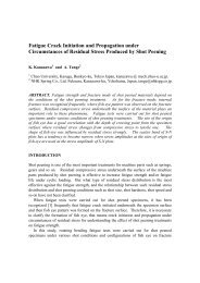
Fig. 2 – <strong>Hyper</strong> <strong>baric</strong><br />
pit furnace featured<br />
with the most<br />
important<br />
modifications<br />
compared to<br />
controlled<br />
atmosphere pit<br />
furnace.<br />
In this case the<br />
quenching is made<br />
out of the furnace.<br />
Fig. 2 – Impianto a<br />
pozzo per la<br />
cementazione<br />
iper<strong>baric</strong>a con<br />
evidenziate le più<br />
importanti modifiche<br />
rispetto al forno a pozzo ad atmosfera controllata.<br />
In questo caso la tempra dovrà essere fatta in una vasca esterna<br />
al forno.<br />
Titanium (see tab 2).<br />
The shaving or the sponge must be very light, and must be<br />
loaded in the furnace with the pieces to be carburised. The<br />
free energy (∆G) of the chemical reaction between Ti and O 2<br />
is lower than that of the alloying element of the steel, so that<br />
the most part of atmosphere oxygen is captured by the Ti,<br />
and avoids forming inter granular oxidation.<br />
The weight, or better the surface of the Ti sponge or shaving<br />
must be sufficient to react with all the oxygen in the atmosphere,<br />
therefore it is important, more than the weight, that<br />
can be ten - twenty grams, the surface extension of the Titanium<br />
.It is best to put it near the fan where there is a good<br />
agitation of the atmosphere.<br />
44<br />
la metallurgia italiana
PROCESSI<br />
THE HYPER BARIC CARBURISING PROCESS<br />
The carburisation can start when the crucible is full of clean<br />
cryogenic nitrogen and in pressure by introducing hydrocarbons,<br />
like that utilized in the low pressure <strong>process</strong>.<br />
The quantity of hydrocarbons, the time of introduction, and<br />
the time of diffusion are the same as the boost-diffusion <strong>process</strong><br />
in vacuum furnace. The technology of carbon enrichment<br />
is the same because it is not possible to analyze the atmosphere<br />
like in the controlled atmosphere furnace.<br />
It is possible to theoretically foresee the boost and diffusion<br />
time utilizing some algorithm obtained from practical experiment<br />
(see ‘Algorithm for carbon diffusion computation in a<br />
vacuum furnace’ ref. 6)) . Moreover, it is easier than in the<br />
vacuum furnace to take out the furnace samples to control the<br />
surface carbon content by spectrometer and the case depth.<br />
It is correct to remember that the oxygen probe is not suitable<br />
to control the inter crystalline oxidation because it’s not<br />
sensible enough. The highest signal utilizable with confidence<br />
is 1,200 mV. Applying the Nerst formula:<br />
mV = 0.0496·K·[logO 2<br />
(air) - log O 2<br />
(furnace)].<br />
It is possible to calculate the minimum partial pressure of O 2<br />
that can read the oxygen probe for a temperature of 1.200K<br />
that is 927°C:<br />
mV 1200 = 0.0496·1200 (-0.678-log x )<br />
calculating x = -20,84,<br />
therefore pO 2<br />
= 10 -20.84 .<br />
The oxygen probe may be therefore only utilized like an<br />
alarm sensor, to signal some anomalous situation in the atmosphere<br />
or in the cleaning of the crucible.<br />
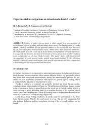
In the fig. 3 there is a picture of the little laboratory furnace<br />
utilized for the first <strong>carburising</strong> tests with cryogenic nitrogen<br />
with 5 part for million of O 2<br />
, Titanium shaving and propane.<br />
The crucible volume is about 1,000 cm 3 .<br />
Before starting the steel sample to be carburised is loaded in<br />
the crucible that is successively sealed. Then the crucible is<br />
washed by five change of nitrogen atmosphere. After the last<br />
change, the pressure in the crucible was put 500 mm of water<br />
column.<br />
At this point can start the heating cycle. When the furnace arrive<br />
in temperature the propane can be introduced.<br />
The boost period was 30 minutes and the diffusion time 2<br />
hours. No addition of nitrogen has been necessary during the<br />
2.30 h of the whole cycle.<br />
The temperature was 950°C and the sample 18 Ni Cr Mo 4<br />
steel. The final results have been: surface carbon content<br />
0.80%; case depth 0.55 mm; inter crystalline oxidation absent.<br />
CONCLUSIONS<br />
The obtained results confirm the validity of the new <strong>process</strong><br />
of hyper <strong>baric</strong> carburisation. The cause of the defects arising<br />
from the traditional technology have been eliminated and the<br />
modifications requested on the furnaces are not expensive.<br />
In same cases, maybe the new furnaces are even cheaper,<br />
both in the buying phase than in the running cost.<br />
The most innovation in the new technology may be so summarized:<br />
1) Compared to vacuum furnace<br />
No necessity of the vacuum or low pressure with consequent<br />
elimination of the vacuum pump and the leakage problems.<br />
Possibility to set up a fan in the <strong>carburising</strong> chamber for better<br />
uniformity in surface carbon and case depth.<br />
Introduction of Titanium shaving or sponge with the <strong>carburising</strong><br />
load, The high affinity of Titanium with the oxygen<br />
avoids totally the inter crystalline oxidation, while in the<br />
low pressure <strong>process</strong>, it is not always so.<br />
2) Compared to controlled atmosphere furnace<br />
The hyper <strong>baric</strong> pressure in the furnace allows avoiding contamination<br />
of the <strong>carburising</strong> atmosphere by the air through<br />
the leakage.<br />
The saving of a continuous flow of endogas make the furnace<br />
more similar to the vacuum, whether for flexibility or for<br />
environment protection.<br />
The introduction, with the <strong>carburising</strong> load, of Titanium shaving<br />
or sponge, avoids totally the inter crystalline oxidation,<br />
while in the controlled atmosphere that is not possible.<br />
BIBLIOGRAPHY<br />
1) Détérioration de la couche superficielle après cémentation<br />
basse pression. B. Clausen, F.Hoffmann, P. Mayr<br />
(Traitement Thermique n° 355 Mai 2004).<br />
2) Influence des réactions gas-solides lors du traitement<br />
thermique des métaux a haute température et sous pression<br />
réduite. Yves Bienvenu et Karine Vieillevigne<br />
(Traitement Thermique n° 362 Avril 2005).<br />
Memorie<br />
3) Comparaison de différents types de refroidissement<br />
après traitement thermochimique et influence sur les caractéristiques<br />
mécanique et métallurgiques. Fernand Da<br />
Costan (Traitement Thermique n° 357 Aout-Sept.<br />
2004).<br />
4) Oxidation intercristalline lors de la cémentation gazeuse<br />
avec endogas. (Grain boundary oxidation in endothermic<br />
gas <strong>carburising</strong> <strong>process</strong>). Elio Gianotti, Irene Calliari,<br />
Marzia Zanesco, Emilio Ramous, DIMEG Università di<br />
Padova/Italia.<br />
Fig. 3 – Laboratory furnace with device for hyper <strong>baric</strong><br />
carburisation.<br />
Fig. 3 – Fornetto di laboratorio attrezzato per le prove di<br />
carburazione iper<strong>baric</strong>a.<br />
5) Calcolo del volume di gas necessario per il lavaggio dei<br />
forni ad atmosfera controllata. Elio Gianotti (La Metallurgia<br />
Italiana n°4 anno 2004).<br />
6) Algorithm for carbon diffusion computation in a vacuum<br />
furnace. Experimental methods predict <strong>carburising</strong> times.<br />
Elio Gianotti (Heat Treating Progress. November<br />
2002 ).<br />
7-8/2006<br />
la metallurgia italiana 45
PROCESSI<br />
7-8/2006 Memorie<br />
CEMENTAZIONE CARBURANTE IPERBARICA<br />
Parole chiave:<br />
acciaio, carburazione,<br />
trattamenti termici, impianti e attrezzature<br />
Una nuova tecnologia (patented) che migliora la cementazione<br />
in bassa pressione nei forni a vuoto e la cementazione<br />
in gas nei sealed quench.<br />
La diffusione a livello industriale della cementazione a bassa<br />
pressione si è ormai ritagliata una fetta di mercato. Essa<br />
presenta l’indubbio vantaggio sull’atmosfera controllata<br />
d’essere meno inquinante. Altri vantaggi vantati dai costruttori<br />
sono di meno facile riscontro come dimostra molta pubblicistica<br />
nata sull’argomento.<br />
Tralasciando alcuni argomenti di carattere più commerciale<br />
come costi di produzione, velocità di carburazione, costi degli<br />
impianti, le discussioni più stimolanti riguardano le caratteristiche<br />
tecnologiche del prodotto rispetto a quelle ottenute<br />
con la vecchia tecnologia dell’atmosfera controllata.<br />
Gli argomenti più controversi riguardano la resistenza a fatica<br />
e la resilienza, condizionate da:<br />
- Impoverimento superficiale di elementi leganti.<br />
- Ossidazione intercristallina.<br />
- Drasticità di tempra con miscele varie di gas e pressioni<br />
ABSTRACT<br />
fino a 20 bar.<br />
Si veda a questo proposito la bibliografia al fondo di questa<br />
memoria ai numeri 1), 2), 3).<br />
Traendo spunto da questi argomenti si è voluto esaminare<br />
da un punto di vista scientifico quali sono i limiti ed i vantaggi<br />
sia del <strong>process</strong>o in bassa pressione che di quello iper<strong>baric</strong>o<br />
e valutare le possibilità tecnologiche del superamento<br />
di alcuni di questi limiti che condizionano le caratteristiche<br />
meccaniche del prodotto cementato e temprato.<br />
Per proporre delle soluzioni tecnologiche nuove che uniscano<br />
ai vantaggi di un <strong>process</strong>o ecologicamente “pulito” delle<br />
caratteristiche metallurgiche migliori vengono quindi dapprima<br />
esaminati:<br />
A Gli equilibri delle fasi solido – gas dei metalli ad alta<br />
temperatura.<br />
B Gli equilibri termodinamici dell’ossidazione intercristallina<br />
superficiale che avviene durante la cementazione<br />
con endogas o nei forni a vuoto che hanno perdite di<br />
vuoto eccessive.<br />
C I problemi che nascono dalla tempra in gas che essendo<br />
meno drastica di quella in olio, malgrado tutti gli accorgimenti<br />
fino ad oggi inventati, genera un decadimento<br />
delle caratteristiche meccaniche compresa quella particolarmente<br />
critica della resilienza. Vedasi studio di Fernand<br />
Da Costan 3) già citato.<br />
46<br />
la metallurgia italiana
TRATTAMENTI TERMICI<br />
A new approach to hardening mechanisms<br />
in the diffusion layer<br />
of gas nitrided α-alloyed steels.<br />
Effects of chromium and aluminium:<br />
experimental and simulation studies<br />
C. Ginter, L. Torchane, J. Dulcy, M. Gantois, A. Malchère, C. Esnouf, T. Turpin<br />
Memorie<br />
Hardening mechanisms in the diffusion layer of gas nitrided α-iron and -steels have been investigated<br />
through the study about effects of chromium (binary alloys and industrial steels) and aluminium<br />
(industrial steel). After nitriding (520°C 48h), nitrogen mass balance between total nitrogen<br />
concentration located in the diffusion zone, experimentally determined, and the expected theoretical<br />
nitrogen concentration, reveals for each alloy a “nitrogen excess”. Jack and Mittemeijer [1-3] suggested<br />
that the volume misfit between semi-coherent nitrides and matrix induces local matrix lattice distorsion,<br />
leading to a local increase of nitrogen solubility in the matrix.<br />
We propose a new approach, based on thermodynamical calculations (Thermo-Calc software), confirmed<br />
by different characterization methods (HRTEM, EDX and X-Ray). Indeed no significant solid solution “N<br />
excess” occurs, but the total nitrogen concentration is explained by complex MN nitrides precipitation,<br />
isomorph of CrN FCC, containing chromium, iron (up to 30at.% at 50µm from the surface), molybdenum<br />
and vanadium. During annealing (520°C 48h), atomic iron fraction in MN nitrides decreases and the<br />
corresponding nitrogen atomic fraction diffuses to the core.<br />
Addition of aluminium in industrial steel strongly increases nitrogen concentration and hardening<br />
(∆=HV x<br />
-HV initial<br />
). Aluminium induces in the diffusion layer precipitation of Fe 4<br />
N and Fe 2-3<br />
N and<br />
precipitates in complex MN FCC nitrides, containing chromium, iron and molybdenum.<br />
Key words: Nitriding, Nitrogen Excess, Nitrides, Chromium, Aluminium, Hardening mechanisms<br />
INTRODUCTION<br />
Gas-nitriding is a thermochemical treatment, applied in aeronautic<br />
and automotive industries, to improve the fatigue<br />
resistance, tribological and anticorrosion properties. The nitrided<br />
case can be divided, as a general rule, into a compound<br />
layer adjacent to the surface (thickness about 10µm)<br />
and a diffusion zone (depth up to 1µm). This study concerns<br />
only the diffusion zone. Relationship between nitrogen concentration<br />
and hardness are strongly dependant of steel composition<br />
and microstructure: different hardening mechanisms<br />
occur, depending of nitriding time and temperature.<br />
The purpose of this paper is to propose a new explanation<br />
about nitrogen localization and improve hardening mechanisms<br />
understanding. Thus effects of chromium and aluminium<br />
were investigated through experimental, simulation<br />
and characterization studies.<br />
Caroline Ginter<br />
Laboratoire de Sciences et Génie des Surfaces (LSGS), Ecole des Mines, Nancy, France<br />
Aubert et Duval, Eramet Group<br />
L. Torchane, J. Dulcy, M. Gantois<br />
Laboratoire de Sciences et Génie des Surfaces (LSGS), Ecole des Mines, Nancy, France<br />
Annie Malchère, C. Esnouf<br />
Laboratory GEMPPM, CECM Group, INSA Lyon, France<br />
T. Turpin<br />
Aubert et Duval, Eramet Group<br />
Paper presented at the 2 nd International Conference<br />
HEAT TREATMENT AND SURFACE ENGINEERING IN AUTOMOTIVE APPLICATIONS<br />
organised by AIM, Riva del Garda, 20-22 June 2005<br />
Binary and ternary alloys have been the subject of many investigations<br />
[1,2,4,5,6], which showed that aluminium and<br />
chromium increase nitrogen content and hardness, due to<br />
the chromium nitrides FCC semi-coherent precipitation. Nevertheless<br />
mechanisms due to aluminium are not clear [7-9].<br />
Moreover hardening mechanisms in industrial steels are<br />
complex and at this time not really understood, in spite of<br />
two important studies about 32CrMoV13 steel [10,11], which<br />
suggested interesting mechanisms related to the chromium<br />
presence.<br />
Therefore it was first necessary to determine nitrogen localization<br />
on binary alloys, and explain the “N excess” observed<br />
by numerous authors in binary and ternary alloys<br />
[1,2,12,13,14]. Then, using the same methodology (experiment,<br />
simulation, characterization) on industrial alloys, nitrogen<br />
localization identification in industrials steels allowed<br />
to suggest several hardening mechanisms, related to<br />
chromium and aluminium presence.<br />
MATERIALS AND EXPERIMENTAL PROCEDURE<br />
Materials investigated in this work are binary alloys (1, 3<br />
and 5wt.%Cr) and about 14 industrial α-alloyed steels manufactured<br />
by Aubert et Duval (heated, quenched then annealed).<br />
Two industrial steels were specially studied; their<br />
chemical composition is given in Table 1.<br />
Samples were gas-nitrided in a vertical furnace during 48h<br />
at 520°C, then quenched in water. The thermogravimetric<br />
measurements were useful to follow the nitrogen mass tran-<br />
7-8/2006<br />
la metallurgia italiana 29
TRATTAMENTI TERMICI<br />
7-8/2006 Memorie<br />
Steel wt.%C wt.%Si wt.%Mn wt.%Ni wt.%Cr wt.%Mo wt.%V wt.%Al<br />
Binary Alloys / T6 wt.%Nexp wt.%N Excess<br />
wt.%N LCth<br />
520°C Kn1 48h<br />
50µm surface 50µm surface<br />
Fe - 1wt.%Cr 0.27 0.44 0.13<br />
Fe - 3wt.%Cr 0.80 1.13 0.29<br />
Fe - 5wt.%Cr 1.35 1.84 0.45<br />
HV50<br />
Initial<br />
K 0.318 0.287 0.532 0.09 3 0.83 0.27 0.013 329<br />
I 0.311 0.330 0.560 0.13 1.73 0.30 0.94 296<br />
sfer through the material from the gas/solid interface. Some<br />
of them were then annealed, in N 2<br />
atmosphere, during 48h at<br />
520°C, then quenched in water.<br />
Nitrided and annealed samples were mechanically characterized<br />
with a micro-hardness tester. Nitrogen profiles in the<br />
nitrided zone were determined from the sample surface through<br />
an electron microprobe analysis. Phases identification<br />
was carried out using X-Ray θ-2θ diffractometer, employing<br />
CoKα radiation.<br />
Nitrides and carbides were examined through Transmission<br />
Electron Microscopy, using a Jeol 200CX (200kV) for conventional<br />
imaging and a Jeol 2010F with a field emission<br />
gun for high resolution imaging and nanoanalysis, equipped<br />
with an INCA Energy Dispersive X-Ray System from<br />
Oxford, with polymer ultra-thin window. TEM observations<br />
were performed on extraction replicas and thin foils. Extraction<br />
carbon replicas were collected on copper grid, after carbon<br />
film deposition on a polished surface and nital<br />
(1.4%HNO 3<br />
+ ethanol) chemical etching. Thin foils were<br />
prepared by spark eroding discs of 3mm diameter (initially<br />
about 700µm in depth), then mechanically polished with a<br />
tripod polisher up reaching 20 to 50µm in depth, to be finally<br />
ion thinned.<br />
Thermodynamical calculations were performed with Thermo-Calc<br />
software, based on Gibb’s free energy minimization<br />
of the defined system. Phases (molar fraction with atomic<br />
chemical composition) appearing at the chemical equilibrium<br />
were simulated, from experimental data (nitriding<br />
temperature, alloy chemical composition, nitrogen concentration).<br />
Table 1 – Chemical<br />
composition and initial<br />
hardness of K and I industrial<br />
steels.<br />
Tabella 1 – Composizione<br />
chimica e durezza iniziale<br />
degli acciai industriali K e I.<br />
I - Binary alloys - Chromium effect<br />
It is well known that nitrogen concentration and hardness<br />
profiles after nitriding depend on chromium concentration.<br />
Indeed, due to the strong Cr-N affinity, chromium combines<br />
with nitrogen to precipitate as fine semi-coherent nitride<br />
CrN FCC, directly responsible for observed hardening.<br />
As hardening mechanisms in industrial steels revealed really<br />
complex, a preliminary work was conducted on binary alloys.<br />
It should be noticed that a discontinuous precipitation,<br />
already observed by several authors [3,11,15,16,17,18,19],<br />
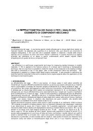
occurs in Fe-3wt.%Cr (Fig.1) and 5wt.%Cr alloys, leading to<br />
a hardness decrease (about 200HV) and does not occur in<br />
steels. Consequently, the objective of this work on binary alloys<br />
was concentrated on nitrogen localization and role. The<br />
Fe 4<br />
N phase often grows at grain boundaries at the compound<br />
and diffusion layers interface, up to 10 or 20µm at the beginning<br />
of the diffusion layer. Consequently, it was decided to<br />
investigate the diffusion layer from 50µm below the surface.<br />
Three binary alloys (1, 3 and 5wt.%Cr) were nitrided at<br />
520°C during 48h with Kn = P(NH 3<br />
)/P(H 2<br />
) 3/2 of 1, then<br />
mass nitrogen concentration profiles were performed (Fig.<br />
1). Nitrogen mass balance was determined for each alloy as<br />
follows: N theoretical, called from now LCth (mass nitrogen<br />
Limited Concentration), subtracted from total amount of N<br />
absorbed [N total<br />
], experimentally determined, revealed N excess<br />
for each alloy below the surface. LCth is defined as the<br />
nitrogen mass concentration involved in nitride precipitation<br />
CrN [N CrN<br />
] and the nitrogen mass concentration dissolved in<br />
the matrix [N α<br />
] (0.043wt.%N at 520°C [20]). LCth depends<br />
on nitriding temperature and alloy chemical composition<br />
Fig. 1 – Mass Nitrogen<br />
concentration profiles versus<br />
nitriding depth of Fe - 1, 3 and<br />
5wt.%Cr alloys, nitrided at<br />
520°C during 48h with Kn 1.<br />
Thermo-Calc phases<br />
simulation at 50µm from the<br />
surface and at LCth, for each<br />
alloy.<br />
Fig. 1- Profili della<br />
concentrazione totale di azoto<br />
in rapporto alla profondità di<br />
nitrurazione delle leghe Fe -<br />
1, 3 e 5wt.% Cr, nitrurate a<br />
520°C per 48h con Kn 1.<br />
Simulazione delle fasi<br />
mediante Thermo-Calc a<br />
50µm dalla superficie ed alla<br />
LCth(mass nitrogen Limited<br />
Concentration), per ogni lega.<br />
Table 2 – Three binary alloys<br />
nitrided at 520°C during 48h<br />
with a Kn of 1. Determination<br />
of nitrogen excess at 50µm<br />
from the surface, from LCth<br />
(wt.%N) and experimental<br />
mass nitrogen concentration<br />
determined at 50µm from the<br />
surface values.<br />
Tabella 2 – Tre leghe binarie nitrurate a 520°C durante 48h con un Kn di 1. Determinazione dell'eccesso di azoto: a 50µm dalla superficie,<br />
dalla LCth (mass nitrogen Limited Concentration - N peso %), concentrazione totale di azoto determinata sperimentalmente a 50µm dai<br />
valori di superficie.<br />
30<br />
la metallurgia italiana
TRATTAMENTI TERMICI<br />
Fig. 2 – Mass Nitrogen<br />
concentration profiles versus<br />
nitriding depth of Fe -<br />
3wt.%Cr alloy, nitrided at<br />
520°C during 48h with Kn 1,<br />
then annealed at 520°C<br />
during 48h (from electron<br />
microprobe analysis).<br />
Thermo-Calc phases<br />
simulation at 50µm from the<br />
surface after nitriding and at<br />
LCth. Micrograph of the<br />
nitrided zone showing<br />
discontinuous precipitation<br />
below the surface.<br />
Fig. 2 – Profili della<br />
concentrazione totale di<br />
azoto (dall’ analisi con<br />
microsonda elettronica) in<br />
rapporto alla profondità di<br />
nitrurazione nella lega Fe - 3<br />
% in peso Cr, nitrurata a 520°C per 48h con Kn 1, quindi sottoposta a trattamento a 520°C per 48h. Simulazione delle fasi mediante<br />
Thermo-Calc a 50µm dalla superficie ed alla LCth. Micrografia della zona nitrurata che mostra la precipitazione discontinua sotto la<br />
superficie.<br />
Memorie<br />
Fig. 3 (left) – Fe-3wt.%Cr, nitrided at 520°C during 48h, nitrides<br />
extracted on carbon replicas at 50µm from the surface,<br />
investigated with HRTEM and EDX. HRTEM precipitate image<br />
and corresponding Fourier Transformation (calculated diffraction<br />
pattern obtained) confirmed that the precipitate is CrN FCC. The<br />
EDX analysis revealed the presence of iron in the nitride. Blank<br />
analysis, close to the precipitate, allowed to identify peaks due to<br />
the environment (copper from the grid, carbon and silicon from<br />
the carbon deposition), and ensure that no matrix was extracted.<br />
Fig. 3 (sinistra) – Lega Fe-3 % in peso Cr, nitrurata a 520°C per<br />
48h; nitruri estratti con repliche di carbonio a 50µm dalla<br />
superficie, esaminata con HRTEM e EDX. L’immagine HRTEM<br />
del precipitato e la corrispondente trasformata di Fourier<br />
(ottenuta l’immagine di diffrazione calcolata) hanno confermato<br />
che si tratta del precipitato CrN FCC. L'analisi EDX ha rivelato<br />
la presenza di ferro nel nitruro. L'analisi di confronto, vicino al<br />
precipitato, ha permesso di identificare picchi dovuti all'ambiente<br />
(rame dalla griglia, carbonio e silicio dal deposito di carbonio) e<br />
assicura che non è stata estratta anche parte della matrice.<br />
(see Table 2). Fig. 1 and Table 2 show that nitrogen concentration<br />
raises with increase of chromium concentration, associated<br />
with a molar fraction nitrides precipitation predicted<br />
by Thermo-Calc, linked to a hardness increase, as reported<br />
by Hekker [2]. These results show that nitrides are directly<br />
responsible for hardness.<br />
Nitrogen concentration enhances with chromium concentration<br />
increase (as shown in Table 2). According to Thermo-<br />
Calc calculations at 50µm from the surface (Fig.1), no significant<br />
solid solution nitrogen excess occurs, but nitrogen<br />
content from LCth depth up to the surface is explained by the<br />
iron precipitation in complex MN nitrides, isomorph of CrN<br />
FCC (about 30at.%). Indeed the iron presence leads to increase<br />
nitrogen concentration involved in nitrides MN precipitation<br />
and enables nitrogen mass balance to be equilibrated.<br />
Note that the iron atomic radius (0.1241nm) is similar to<br />
the chromium radius (0.1249nm) and FeN, obtained by PVD<br />
(lattice parameter 0.430nm), is isomorph of CrN FCC (lattice<br />
parameter 0.414nm). Iron acts like chromium, allowing nitrides<br />
to keep the same size, morphology, semi-coherence with<br />
the matrix and so possibly the same effect on hardness.<br />
In order to check nitrogen mobility, nitrided Fe-3wt.%Cr alloy<br />
was annealed at nitriding temperature and time (520°C,<br />
48h). Fig. 2 shows nitrogen profiles after nitriding and after<br />
annealing versus nitriding depth, and confirms that nitrogen<br />
diffuses to the core. After annealing, nitrogen concentration<br />
profile presents a plateau, coinciding with LCth. Thermo-<br />
Calc results (fraction phases with chemical composition, at<br />
50µm from the surface for both of them and at LCth depth)<br />
are also plotted on Fig. 2. Thermo-Calc indicates that during<br />
annealing, the phase (Fe x<br />
,Cr y<br />
)N tends to a more stable phase<br />
CrN, leading to loss of iron - about 22at.% - (and corresponding<br />
nitrogen atomic fraction) associated with the molar<br />
fraction nitrides decrease by about 33% (9mol.% to<br />
6.8mol.%), which also should contribute to decrease the<br />
hardness, too.<br />
Microstructural characterizations were performed on nitrides<br />
from carbon replicas and thin foils with High Resolution<br />
Transmission Electron Microscopy and Energy Dispersive<br />
X-Ray. For both cases after nitriding and after annealing, at<br />
50µm from the surface, precipitates with platelet morphology,<br />
present at grain boundaries and in discontinuous precipitation,<br />
were confirmed by High Resolution Image Fourier<br />
Transformation to be chromium nitrides CrN FCC. Then<br />
EDX analysis was performed on them, after verification close<br />
to the precipitate that the ferritic matrix was not extracted.<br />
In the first case, after nitriding, EDX analysis (Fig.3) confirmed<br />
that nitrides (10 to 20nm diameter, 2-10nm thick) contain<br />
iron, with an iron fraction distribution of 14-37at%, in<br />
agreement with Thermo-Calc prediction (22at.%Fe).<br />
In the second case, after annealing, Thermo-Calc predicts an<br />
iron concentration of 8at.% in nitrides. Actually, the coarser<br />
nitrides (20nm diameter), after EDX analysis (Fig.4), contain<br />
from 5 to 14at.%Fe. These investigations confirmed<br />
that nitrides lost iron and corresponding nitrogen (1 to 1<br />
atom) during annealing, the released nitrogen diffusing to<br />
the core.<br />
7-8/2006<br />
la metallurgia italiana 31
TRATTAMENTI TERMICI<br />
7-8/2006 Memorie<br />
Fig. 4 (right) – Fe-3wt.%Cr, nitrided at 520°C during 48h then<br />
annealed at 520°C during 48h, nitrides extracted on carbon<br />
replicas at 50µm from the surface, investigated with HRTEM and<br />
EDX. HRTEM precipitate image and corresponding Fourier<br />
Transformation (calculated diffraction pattern obtained)<br />
confirmed that the precipitate is CrN FCC. The EDX analysis<br />
revealed the presence of iron in the nitride, but less than in<br />
previous case (Fig.3). The EDX analysis revealed the presence of<br />
iron in the nitride. Blank analysis, close to the precipitate, allowed<br />
to identify peaks due to the environment (copper from the grid,<br />
carbon and silicon from the carbon deposition), and ensure that<br />
no matrix was extracted.<br />
Fig. 4 (destra) – Lega Fe-3 % in peso Cr, nitrurata a 520°C per<br />
48h quindi sottoposta a trattamento a 520°C per 48h: nitruri<br />
estratti con repliche di carbonio a 50µm dalla superficie,<br />
esaminati con HRTEM e EDX. L’immagine HRTEM del<br />
precipitato e la corrispondente trasformata di Fourier (ottenuta<br />
l’immagine di diffrazione calcolata) hanno confermato che il<br />
precipitato è CrN FCC. L'analisi EDX ha rivelato la presenza di<br />
ferro nel nitruro, ma in quantità minore rispetto al caso di Fig.3.<br />
L'analisi di confronto, vicino al precipitato, ha permesso di<br />
identificare i picchi dovuti all'ambiente (rame dalla griglia,<br />
carbonio e silicone dal deposito di carbonio) e assicura che non è<br />
stata estratta anche parte della matrice.<br />
II - Industrial steels<br />
A nitriding treatment (520°C 48h Kn3) on 14 different industrial<br />
steels put into evidence the well known preponderant<br />
roles of chromium and aluminium on nitrogen concentration<br />
and hardness profiles. As in binary alloys, a chromium content<br />
increase leads to nitrogen concentration and hardness<br />
enhancements, due to a semi-coherent fine MN FCC precipitation<br />
fraction augmentation. Two steels were selected to<br />
be representative of chromium effect (K 3wt.%Cr) and aluminium<br />
effect (I 1.73wt.%Cr 0.94wt.%Al).<br />
The same methodology applied to binary alloys was used to<br />
study both industrial steels:<br />
• Experiment and first characterization : nitriding then nitrogen<br />
concentration and hardness profiles performed,<br />
• Phases (molar fraction and chemical composition) simulations<br />
by means of the software Thermo-Calc,<br />
• TEM and EDX characterization on nitrides and carbides.<br />
A - Chromium effect: K steel<br />
K steel, which contains 3wt.%Cr, was nitrided at 520°C during<br />
48h. Nitrogen concentration and hardness profiles were<br />
performed then Thermo-Calc calculations at 50µm from the<br />
surface. Hardening (HV x<br />
- HV initial<br />
) is represented as a nitrogen<br />
concentration function (Fig.5). Yet Thermo-Calc predicts<br />
that nitrides fraction keeps on rising linearly with nitrogen<br />
concentration. It can be deduced then that nitrides<br />
precipitation contributes directly to hardening. Another interesting<br />
result of Thermo-Calc calculations (molar fraction<br />
phase versus nitrogen concentration) is that nitride precipitation<br />
requires the entire carbides transformation, in order to<br />
release chromium, vanadium and molybdenum.<br />
Thermo-Calc does not make the difference between vanadium<br />
carbide, vanadium carbonitride and chromium nitride,<br />
as they crystallize in the same structure FCC with a similar<br />
lattice parameter. As reported by Locquet [10], vanadium<br />
carbides, present before nitriding, transform into carbonitride<br />
V(C,N), keeping the same size, morphology and localization.<br />
Considering that result, they should keep the same molar<br />
fraction, which is small (0.58mol.%) compared to the<br />
MN+V(C,N) one, predicted by Thermo-Calc at 50µm from<br />
the surface (9.52mol.%).<br />
At 50µm from the surface, nitrogen mass concentration raises<br />
to 1.27wt.%N. Considering that LCth, calculated including<br />
chromium, vanadium and molybdenum, is 1.00wt.%N,<br />
a “N excess” was revealed equal to 0.28wt.%N. Nitrogen<br />
concentration is once again explained, according to Thermo-<br />
Calc calculations, by the iron alloying in MN complex nitrides<br />
(M stands for Molybdenum, Vanadium and Chromium),<br />
isomorph of CrN FCC. Iron, molybdenum and vanadium<br />
seem to act like chromium and keep the same role towards<br />
hardening mechanisms (especially MN FCC semi-coherent<br />
nitrides).<br />
Some investigations on thin foils at 50µm from the surface<br />
after nitriding, which revealed two different MN precipitations,<br />
as reported by Locquet [10]. Indeed globular nitrides<br />
indexed as MN FCC germinate at the matrix/carbide interface,<br />
due to carbides transformation. Diffraction patterns and<br />
corresponding dark field revealed the presence of semicoherent<br />
finer nitrides MN FCC, with platelet morphology,<br />
Fig. 5 – Hardening (HVx -<br />
HVinitial) representation as a<br />
function of mass nitrogen<br />
concentration of I and K<br />
steels, nitrided at 520°C<br />
during 48h with a Kn of 3.<br />
Phases (molar fraction and<br />
chemical composition)<br />
simulation by Thermo-Calc at<br />
50µm from the surface.<br />
Fig. 5 – Rappresentazione<br />
dell’indurimento (HVx -<br />
HViniziale) in funzione della<br />
concentrazione totale di azoto<br />
negli acciai K e I, nitrurati a<br />
520°C per 48h con un Kn di<br />
3. Simulazioni di fasi<br />
(frazione molare e<br />
composizione chimica)<br />
mediante Thermo-Calc a<br />
50µm dalla superficie.<br />
32<br />
la metallurgia italiana
TRATTAMENTI TERMICI<br />
due to the nitrogen and elements dissolved in the matrix<br />
combination.<br />
Presently, hardening mechanisms could be related as follows<br />
(from [10,11] and Thermo-Calc calculations):<br />
• Fine semi-coherent nitrides MN FCC (M stands for Fe,<br />
Cr, Mo and V) precipitate from the combination of nitrogen<br />
and elements dissolved in the matrix. They are known<br />
to contribute in a large part to nitriding hardening.<br />
• M 23<br />
C 6<br />
carbides (inter- and intragranular) transform into<br />
globular mixed (Fe, Cr, Mo, V)N FCC nitrides. The chemical<br />
composition of these nitrides will be soon investigated.<br />
Their contribution to nitriding hardening is not already<br />
clearly identified.<br />
• Vanadium carbides present before nitriding transform into<br />
carbonitride V(C,N), and can not induce more hardness.<br />
Memorie<br />
B - Aluminium effect: I steel<br />
Both steels I (1.73wt.%Cr and 0.94wt.%Al) and K (3wt.<br />
%Cr) were nitrided at 520°C during 48h with a Kn of 3. Nitrogen<br />
concentration and hardness profiles were performed.<br />
Then the hardening (HV x<br />
- HV initial<br />
) has been represented as<br />
a function of mass nitrogen concentration, Fig. 5. Even<br />
though both steels have the same CLth (the same nitrogen<br />
concentration involved in (Cr, Mo, V, Al)N precipitation),<br />
steel I shows a nitrogen concentration at 50µm from the surface<br />
of 2.6wt.%N (1.3wt.%N for steel K), and hardening<br />
(∆=HV x<br />
-HV initial<br />
) of 763HV (536HV for steel K)!<br />
Nitrogen concentration below the surface is explained first<br />
by thermodynamical simulation and confirmed by HRTEM<br />
and EDX, as the iron alloying in complex MN FCC nitrides<br />
(M = Cr, Mo, V) for both steels I and K. Nevertheless the<br />
iron concentration seems to be limited to about 20at.%.<br />
Thermo-Calc predicts hexagonal AlN precipitation, but they<br />
were not observed. In industrial steels, iron and aluminium<br />
combine with chromium and molybdenum to form (Cr, Mo,<br />
Fe, Al)N FCC precipitates (chemical composition is given<br />
Table 3).<br />
Nitrogen concentration observed in I steel is also explained<br />
below the surface by the γ’ (Fe 4<br />
N) and ε (Fe 2-3<br />
N) precipitation<br />
in the diffusion layer, confirmed by X-Ray analysis, up<br />
to 125µm in depth in the diffusion layer, which corresponds<br />
to 1.8wt.%N.<br />
Presently, hardening mechanisms could be explained as follows:<br />
• Semi-coherent platelets were analyzed and identified as<br />
complex MN (M = Fe, Al, Cr, Mo) FCC. Iron would be<br />
contained in MN from LCth depth up to the surface. These<br />
nitrides, known to contribute mainly to hardening<br />
(∆HV), are the result of the combination of nitrogen and<br />
elements dissolved in the matrix. Thermo-Calc simulation<br />
of the matrix composition before nitriding for steels I and<br />
K (Table 4) shows that the nitrogen concentration involved<br />
in MN semi-coherent precipitation is twice more important<br />
for I steel than for K steel, which could explain the<br />
huge hardening observed below the surface in I steel.<br />
• M 23<br />
C 6<br />
and M 7<br />
C 3<br />
carbides, present in bainitic structure<br />
before nitriding, transform into globular incoherent com-<br />
Fig. 6 (left) – I steel (1.73wt.Cr 0.94wt.%Al), nitrided at 520°C<br />
during 48h. Nitrides were extracted on carbon replicas at 50µm<br />
from the surface, investigated with HRTEM and EDX. HRTEM<br />
precipitate image and corresponding Fourier Transformation<br />
(calculated diffraction pattern obtained) confirmed that elongated<br />
carbide M7C3 transform partially into globular nitrides (Cr, Fe,<br />
Al, Mo)N FCC.<br />
Fig. 6 (sinistra) – Acciaio I (1.73% Cr e 0.94wt.% Al), nitrurato a<br />
520°C per 48h. Sono stati estratti nitruri su repliche di carbonio a<br />
50µm dalla superficie, esaminati mediante HRTEM e EDX.<br />
L'immagine del precipitato HRTEM e la corrispondente<br />
trasformata di Fourier (ottenuta l’immagine di diffrazione<br />
calcolata) hanno confermato che il carburo allungato M7C3 si<br />
trasforma parzialmente in nitruri globulari (Cr, Fe, Al, Mo)N<br />
FCC.<br />
plex MN FCC (M stands for Cr, Al, Mo and Fe - Fe below<br />
the surface up to LCth depth -). Elongated carbides transform<br />
only partially into nitrides (as observed Fig.6), but<br />
globular ones, which are smaller, transform wholly (as observed<br />
Fig.7). These nitrides germinate at the matrix/carbide<br />
interface. Their contribution to nitriding hardening is<br />
not yet clearly identified.<br />
• If γ’ and ε precipitate with well-known needle morphology<br />
in lath interfaces, it can be expected that their contribution<br />
to hardening is not significant.<br />
CONCLUSION<br />
Thermo-Calc calculation associated with microstructural<br />
analysis (HRTEM and EDX) allows the determination of nitrogen<br />
localization, which leads to a better understanding of<br />
chromium and aluminium effects on hardening mechanisms.<br />
Binary Alloys<br />
1- Chromium concentration increase in binary alloys induces<br />
nitrogen content enhancement, linked to MN FCC nitrides<br />
fraction and hardness augmentation, showing that<br />
semi-coherent MN nitrides are responsible for hardening.<br />
Table 3 – I steel nitriding at<br />
520°C during 48h. Results of<br />
EDX analysis (average and<br />
range) performed on nitrides<br />
extracted at 50µm from the<br />
surface, with corresponding<br />
sizes.<br />
I T1 50µm surface M Chemical composition (at.%) Size<br />
MN FCC Al Cr Fe Mo (nm)<br />
Semi-coherent Average / 3 zones 45 18 23 13 3-13<br />
platelets Range 41-49 13-24 19-29 6-17 length<br />
Globular germinated Average / 22 particles 13 73,5 7 7 6-28<br />
at the carbides/α interface Range 3-23 61-82 2-13 1-12 length<br />
Tabella 3 – Nitrurazione<br />
dell'acciaio I a 520°C per<br />
48h. Risultati dell’analisi<br />
EDX (media e intervallo dei<br />
valori) effettuata sui nitruri estratti a 50µm dalla superficie, con le corrispondenti dimensioni.<br />
Bainitic lath interface Average / 4 zones 61 18 8 13 3-9<br />
Range 57-66 12-26 4-12 9-16 length<br />
7-8/2006<br />
la metallurgia italiana 33
TRATTAMENTI TERMICI<br />
7-8/2006 Memorie<br />
Phases molar fraction /<br />
Chemical mass composition α<br />
wt.%N<br />
wt.%Cr α<br />
wt.%Mo α<br />
wt.%V α<br />
wt.%Al MN<br />
α from α<br />
K core 650°C<br />
5.54mol.%M 23<br />
C 6<br />
1.16 0.12 0.02 0.01 0.34<br />
0.08mol.%M7C3, 93.77mol.%α<br />
I core 620°C<br />
2.61mol.%M 23<br />
C 6<br />
, 0.28 0.03 0.98 0.59<br />
2.86mol.%M 7<br />
C 3<br />
, 94.53mol.%α<br />
2- After nitriding, complex MN (M = Fe and Cr), isomorph<br />
of CrN FCC, are observed with a maximum of iron atomic<br />
fraction below the surface, which explains nitrogen<br />
content. Iron acts like chromium, inducing nitrides fraction<br />
and hardening increase. It was confirmed that in the<br />
nitrided Fe-3wt.%Cr alloy, at 50µm from the surface,<br />
nitrides MN FCC, with platelet morphology contain<br />
between 14 and 37at.%Fe (22at.%Fe simulated by Thermo-Calc).<br />
3- After annealing, under temperature effect nitrogen diffuses<br />
to the core. From the surface up to LCth depth, nitrides<br />
MN loose partially iron and nitrogen corresponding<br />
(1 N atom to 1 Fe atom), decreasing MN molar fraction.<br />
From LCth depth up to the core, as all chromium was<br />
not used to precipitate, the released nitrogen can combine<br />
with chromium, to form CrN and so increase CrN<br />
molar fraction and hardening.<br />
Industrial steels<br />
1- After nitriding several industrial a-alloyed steels, it<br />
could have been concluded that chromium and aluminium<br />
enhance nitrogen concentration and hardness profiles,<br />
molybdenum and vanadium having a minor importance.<br />
2- In industrial steels without aluminium, nitrogen mass<br />
balance can be explained, according to Thermo-Calc simulations,<br />
by complex MN nitrides, isomorph of CrN<br />
FCC, containing chromium, iron, molybdenum and vanadium.<br />
Before nitriding, the largest part of chromium,<br />
molybdenum and vanadium precipitated as carbides VC<br />
and M 23<br />
C 6<br />
. These last ones transform during nitriding<br />
into globular incoherent MN FCC. A small fraction of<br />
chromium, molybdenum and vanadium, dissolved in the<br />
matrix, combines with nitrogen and precipitates as semicoherent<br />
platelets MN FCC. More HRTEM and EDX<br />
investigations will be performed to identify chemical<br />
compositions of both kinds of precipitates.<br />
3- In industrial steels, aluminium allows a huge nitrogen<br />
concentration and induces significantly important hardening.<br />
Below the surface, nitrogen mass balance is first<br />
explained, according to Thermo-Calc simulation and<br />
confirmed by characterization, by complex nitrides MN,<br />
isomorph of CrN FCC, containing iron (atomic fraction<br />
seems to be limited to 30at.%), aluminium, chromium<br />
and molybdenum. γ’ and ε phases precipitation in the<br />
diffusion layer allows nitrogen balance to be equilibrated.<br />
Another new important result is that aluminium precipitates<br />
in complex MN nitrides FCC, and not as hexagonal<br />
AlN and contributes to an important hardness increase.<br />
REFERENCES<br />
Table 4 – From Thermo-Calc<br />
simulation of the ferritic<br />
phase chemical composition,<br />
determination of the mass<br />
nitrogen concentration, which<br />
could precipitate as semicoherent<br />
MN FCC nitrides<br />
with elements dissolved in the<br />
matrix - K and I steels -<br />
Simulation at the last pretreatment<br />
before nitriding<br />
(650°C for K and 620°C for I).<br />
Tabella 4 – Da simulazione Thermo-Calc della composizione chimica della fase ferritica, determinazione della concentrazione totale di<br />
azoto, che può precipitare in forma di nitruri semi-coerenti di MN FCC, con M costituito dagli elementi dissolti nella matrice ( acciai I e K ).<br />
Simulazione all'ultimo pretrattamento prima della nitrurazione (650°C per K e 620°C per I).<br />
Fig. 7 (right) – HRTEM precipitate image (and Fourier Transform<br />
not shown here) and EDX analysis confirmed that globular<br />
carbides transform wholly into globular nitrides MN FCC, that<br />
semi-coherent platelets are MN FCC and that precipitates on lath<br />
interfaces are also MN FCC. M stands for iron, aluminium (in<br />
chromium presence, aluminium does not precipitate as hexagonal<br />
AlN), chromium and molybdenum.<br />
Fig. 7 (destra) – Immagine HRTEM del precipitato (la<br />
trasformata di Fourier non è qui riportata) e analisi EDX hanno<br />
confermato che i carburi globulari si trasformano interamente in<br />
nitruri globulari MN FCC, che le piastrine semi-coerenti sono MN<br />
FCC e che anche i precipitati sulle interfacce sono MN FCC. M<br />
sta per ferro, alluminio (in presenza di cromo, l'alluminio non<br />
precipita come AlN esagonale), cromo e molibdeno.<br />
[1] D.H. JACK, K.H. JACK, Materials Science and Engineering<br />
11, (1973) p. 1-27<br />
[2] P.M. HEKKER, E.J. MITTEMEIJER, H.C.F. ROZEN-<br />
DAAL, The influence of Nitriding on the Microstructure<br />
and Stress State of Iron and Steel (1985) p. 51-61<br />
[3] E.J. MITTEMEIJER, H.C.F. ROZENDAAL, P.J. VAN<br />
DER SCHAAF, R.T. FURNEE, The influence of Nitriding<br />
on the Microstructure and Stress State of Iron and<br />
Steel (1985) p. 109-117<br />
[4] B.J. LIGHTFOOT, D.H. JACK, Heat Treatment’73,<br />
London, (1973) p. 59-65<br />
[5] H.J. SPIES, S. BÖHMER, HTM 39 (1984) p. 1-6<br />
[6] Y.M. LAKHTIN, Y.D. KOGAN, Mashinostroenie, Moscow,<br />
(1976)<br />
[7] V.A. PHILLIPS, A.U. SEYBOLT, Trans. Of the Metall.<br />
Society of AIME 242, (1968) p. 2415-2422<br />
[8] H.C.F. ROZENDAAL, E.J. MITTEMEIJER, P.F. CO-<br />
LIJN, P.J. VAN DER SCHAAF, Metall. Trans. A 14, 2<br />
(1983) p. 395-399<br />
[9] J.P. CALVEL, Détermination expérimentale des contraintes<br />
résiduelles introduites par la nitruration gazeuse<br />
d’aciers 35CD4 et 40CAD6.12 - Relations avec le<br />
34<br />
la metallurgia italiana
TRATTAMENTI TERMICI<br />
durcissement, PhD Thesis INPT, France (1983)<br />
[10] J.N. LOCQUET, R. SOTO, L. BARRALLIER, A.<br />
CHARAÏ, Microsc. Microanal. Microstruct. 8 (1997)<br />
p. 335-352<br />
[11] M. SENNOUR, Apport de la microscopie électronique<br />
en transmission et de la spectroscopie EELS à la caractérisation<br />
de nitrures (AlN, CrN) dans le fer et l'alliage<br />
Fe-Cr, PhD Thesis INSA Lyon, France (2002)<br />
[12] E.J. MITTEMEIJER, Journal of Metals (1985) p.16-20<br />
[13] E.J. MITTEMEIJER, M.A.J. SOMERS, Proc. Int.<br />
Conf. on High Nitrogen Steels, Lille, France (1989)<br />
[14] R.E. SCHACHERL, P.C.J. GRAAT, E.J. MITTE-<br />
MEIJER, Metallurgical and Materials Transactions A<br />
35 (2004) p. 3387-98<br />
[15] M.SENNOUR, P.H. JOUNEAU, C. ESNOUF, Journal<br />
of Materials Science 39 (2004) p.1-11<br />
[16] B. MORTIMER, P. GRIEVESON, K.H. JACK, Scandinavian<br />
Journal of Metallurgy 1, (1972) p. 203-209<br />
[17] P.C. VAN WIGGEN, H.C.F. ROZENDAAL, E.J. MIT-<br />
TEMEIJER, Journal of Materials Science (1985) p.<br />
4562-4582<br />
[18] M.A.J. SOMERS, R.M. LANKREIJER, E.J. MITTE-<br />
MEIJER, Philosophical Magazine A 59 (1989) p. 353-<br />
378<br />
[19] R.E. SCHACHERL, P.C.J. GRAAT, E.J. MITTE-<br />
MEIJER, Z.Metallkunde 93 (2002) 5 p.468-477<br />
[20] E.J. MITTEMEIJER, M.A.J. SOMERS, Surface Engineering<br />
13 (1997) 6<br />
Memorie<br />
ABSTRACT<br />
UN NUOV0 APPROCCIO AI MECCANISMI DI INDURIMENTO<br />
NELLO STRATO DI DIFFUSIONE DEGLI ACCIAI LEGATI,<br />
CON STRUTTURA α NITRURATI IN FASE GASSOSA<br />
EFFETTI DI CROMO E ALLUMINIO:<br />
STUDIO SPERIMENTALE E DI SIMULAZIONE<br />
Parole chiave: trattamenti termici, nitrurazione, acciaio,<br />
metallurgia fisica, caratterizzazione materiali<br />
Sono stati studiati i meccanismi di indurimento nello strato<br />
di diffusione di ferro e acciai con struttura α nitrurati in fase<br />
gassosa, attraverso l’analisi degli effetti della presenza di<br />
cromo (leghe binarie ed acciai industriali) e di alluminio<br />
(acciaio industriale). Dopo la nitrurazione (520°C 48h), il<br />
bilancio di massa dell’azoto fra la concentrazione di azoto<br />
totale nella zona di diffusione, determinata sperimentalmente,<br />
e la concentrazione di azoto prevedibile in via teorica, rivela<br />
per ogni lega "un eccesso di azoto". Jack e Mittemeijer<br />
[1-3 ] hanno suggerito che le differenze in volume fra i nitruri<br />
semi-coerenti e la matrice induca la distorsione locale<br />
del reticolo della matrice, e ciò porti ad un aumento locale<br />
della solubilità dell'azoto nella matrice. Nel presente studio<br />
si propone un nuovo approccio, basato su calcoli termodinamici<br />
(software Thermo-Calc), confermati mediante diversi<br />
metodi di caratterizzazione (HRTEM, EDX e raggi X).<br />
In effetti non si riscontra alcuna significativo "eccesso di N"<br />
in soluzione solida, ma la concentrazione totale nell'azoto si<br />
spiega con la precipitazione di nitruri complessi metalloazoto<br />
(MN), isomorfi di CrN cubico a facce centrate, contenenti<br />
cromo, ferro (fino a 30 % atomico, a 50µm dalla superficie),<br />
molibdeno e vanadio. Durante il trattamento<br />
(520°C 48h), la frazione atomica di ferro nei nitruri complessi<br />
(MN) diminuisce e la corrispondente frazione atomica<br />
di azoto si diffonde all’interno.<br />
L’aggiunta di alluminio nell’acciaio industriale permette di<br />
aumentare decisamente la concentrazione di azoto e l’indurimento<br />
(∆=HV x<br />
-HV iniziale<br />
). L'alluminio induce, nello strato<br />
di diffusione, precipitazione di Fe 4<br />
N e di Fe 2-3<br />
N e di precipitati<br />
nei nitruri complessi metallo-azoto (MN) a struttura<br />
FCC, contenenti cromo, ferro e molibdeno.<br />
7-8/2006<br />
la metallurgia italiana 35
TRATTAMENTI TERMICI<br />
The behaviour of decarburized layers<br />
in steel nitriding<br />
I. Calliari, M. Dabalà, E. Ramous, M. Zanesco, E. Gianotti<br />
Samples of quenched and tempered 40CrMo4 steel, previously surface decarburized at different depths,<br />
have been submitted to gaseous nitriding. The surface layers after decarburization and nitriding was<br />
examined by optical microscopy (OM), scanning electron microscopy (SEM) and microhardness tests.<br />
The distribution of iron nitrides in the diffusion layer was analyzed by X-ray diffraction (XRD). The<br />
nitrogen and carbon profiles in the diffusion layers were determined by scanning electron microscope<br />
equipped with a wavelength dispersive spectrometer (EPMA-WDS).<br />
For all the specimens, the highest hardness values only change slightly with increasing time and<br />
temperature of decarburization, while case hardness depths decrease.<br />
In all the specimens, the nitriding depth, as determined by the nitrogen profile, is larger than the one<br />
determined by the hardness profile.<br />
Memorie<br />
Key words: decarburization, nitriding, steel, 40CrMo4<br />
INTRODUCTION<br />
The surface microstructure on nitriding steels has been widely<br />
investigated and discussed in several papers (1-4). The<br />
nitriding <strong>process</strong> develops a zone which can be subdivided<br />
into a compound (white) layer, with carbo-nitrides, and an<br />
underlying diffusion layer. The compound layer is formed<br />
by nitrides and carbonitrides, while interstitial nitrogen and<br />
alloy forming elements (Cr, Mo, Al, and V) nitrides are present<br />
in the diffusion layer.<br />
The nitrided layers structure depends on the interaction<br />
between the diffusional nitrogen and original steel microstructure,<br />
normally ferrite and carbides , caused by the tempering<br />
heat treatment, which is usually performed on steel<br />
before nitriding. A special role is played by the transformation<br />
of Cr carbides to Cr nitrides (5), so the C may diffuse<br />
interstitially from the diffusion layer to the compound layer,<br />
where it forms carbides. This transformation explains why<br />
the final microstructure of nitrided steels depends not only<br />
on the C content but also on the C distribution(6) in the prior<br />
steel microstructure. The nitriding treatment modifies the<br />
carbides and C distribution which then affects also the hardness<br />
profile in the N-enriched layer(7). Occasionally, in industrial<br />
practice, the nitrided work pieces can present some<br />
surface decarburization due to previous heat treatments. The<br />
behaviour of nitrided samples after a controlled surface decarburization<br />
has been examined in this study.<br />
The main differences between decarburized and non-decarburized<br />
layers are obviously the lower carbides content and<br />
the larger ferrite grain sizes in the former. The low carbide<br />
content determines that nitrides may form by precipitation<br />
from ferrite and not by carbides decomposition. The large<br />
ferrite grain size implies that the grain boundary nitrogen<br />
diffusion increases and the grain boundary nitrides precipitation<br />
is enhanced.<br />
Moreover, the study could give more information about the<br />
I. Calliari, M. Dabalà, E. Ramous, M. Zanesco<br />
DIMEG Department of Innovation in Mechanics and Management, Padova<br />
E. Gianotti<br />
Heat Treatments Ferioli & Gianotti Spa, Rivoli (TO)<br />
Paper presented at the (2nd International Conference<br />
HEAT TREATMENT AND SURFACE ENGINEERING IN AUTOMOTIVE APPLICATIONS,<br />
organised by AIM, Riva del Garda, 20-22 June 2005<br />
effect of pre-oxidation treatments, often suggested to improve<br />
nitrogen take-up, and about the redistribution of carbon<br />
observed during nitriding.<br />
EXPERIMENTAL PROCEDURES<br />
The specimens have been obtained from a bar (diameter 28<br />
mm) of commercial steel 4140 quenched (in oil at 840°C)<br />
and tempered (2 h at 600°C).<br />
Six different thermal cycles, aimed at obtaining surface decarburization,<br />
were conducted in the experimental condition<br />
reported in table 2.<br />
After metallographic preparation, the cross-sections of the<br />
specimens were etched with Nital 4% in order to characterize<br />
the structure and evaluate the decarburized thickness through<br />
optical microscopy.<br />
The decarburized specimens were submitted to the following<br />
nitriding treatment: all the specimens were heated at<br />
350°C in air, from 350°C to 400°C in N 2<br />
and then kept at<br />
400°C for 30 minutes in N 2<br />
, from 400°C to 510°C in N 2<br />
and<br />
then kept at 510°C for 72 h with a NH 3<br />
dissociation of 25%.<br />
Steel<br />
Composition %<br />
C Mo Mn Cr Ni Cu Si<br />
4140 0,432 0,2 0,85 1,148 0,122 0,267 0,243<br />
Table 1 – Composition of the nitrided steel.<br />
Tabella 1 – Composizione dell’ acciaio.<br />
Sample Thermal cycle Cooling<br />
1 3 h 800°C Air<br />
2 4 h 800°C Air<br />
3 3 h 840°C Air<br />
4 4 h 840°C Air<br />
5 3 h 900°C Air<br />
6 4 h 900°C Air<br />
Table 2 – Decarburization heat treatment.<br />
Tabella 2 – Trattamenti per ottenere gli strati decarburati.<br />
7-8/2006<br />
la metallurgia italiana 15
TRATTAMENTI TERMICI<br />
7-8/2006 Memorie<br />
The cross-sections of the nitrided specimens were etched<br />
with Nital 4% to observe the microstructure and subsequently<br />
etched with Murakami in order to evaluate the distribution<br />
of carbides, by light and SEM microscopy. Microhardness<br />
profiles were performed using a load of 200g. The concentration<br />
profiles of nitrogen and carbon in the nitride<br />
layers have been determined by GDOS spectrometry on the<br />
surface layers, and by the JEOL-JXA microprobe (with<br />
spectrometers 4 WDS). A Siemens D5000 X-ray diffractometer<br />
with Cu Kα radiation was used to examine the phases<br />
of white surface layers.<br />
RESULTS AND DISCUSSION<br />
1. Decarburized samples<br />
Table 3 reports the values of decarburized depths, surface<br />
hardness after nitriding and effective depth of nitriding ; it<br />
is evident that the decarburized thickness increases with time<br />
and temperature of heat treatment.<br />
In fig.1 an example(sample 2, 800°C,4h) of the microstructure<br />
of the decarburized surface layer is reported. Particularly<br />
in the samples n. 5 and 6, the decarburization produces<br />
a completely ferritic<br />
microstructure with coarse grains. The increase in ferrite<br />
grain size is important because, during the nitriding <strong>process</strong>,<br />
the nitrogen diffuses preferentially along the grain bounda-<br />
Surface Effective<br />
Depth of hardness depth<br />
Sample Decarbu- after after<br />
rising (µm) nitriding nitriding<br />
(HV 0.5<br />
) (µm)<br />
0 0 841+-12 481<br />
1 150 817+-10 476<br />
2 290 836+-16 470<br />
3 300 810+-12 444<br />
4 310 841+-12 415<br />
5 460 814+-14 436<br />
6 490 817+-16 388<br />
Table 3 – Decarburized depths, surface hardness after nitriding<br />
and effective depth of nitriding.<br />
Tabella 3 – Spessori degli strati decarburati, durezze superficiali<br />
dopo nitrurazione e spessori efficaci di nitrurazione.<br />
Fig. 1 – Optical micrograph of sample 2 (800°C,4h).<br />
Fig. 1 – Microstruttura del campione 2 dopo decarburazione<br />
(800°C, 4 ore).<br />
Fig. 2 – Hardness profiles of samples 5,6 and 0.<br />
Fig. 2 – Profili di microdurezza dei campioni n. 5, 6 e 0.<br />
ries. As the grain size increases, the nitrogen gradient concentration<br />
between grain core and grain boundaries may increase<br />
and the nitrides precipitation along the grain boundaries<br />
is favoured.<br />
2. Nitrided samples<br />
2a. Surface hardness<br />
The surface hardness values measured after nitriding are reported<br />
in the 3 rd column of table 3. The values are the mean<br />
of 10 measurements randomly taken on the surface. Samples<br />
from 1 to 6 have been heat treated as indicated in table<br />
2, while sample 0 has only been nitrided in the same experimental<br />
conditions of 1-6 but not decarburized.<br />
All the hardness values are higher than the 600HV required<br />
by the standard. The surface hardness is not affected by the<br />
different rate of decarburization, as sample 0 has the same<br />
hardness as the others. High nitrogen enrichment in the<br />
compound layer probably compensates the carbon loss and<br />
the resulting hardness can only be determined by nitriding.<br />
2b. Hardness profiles<br />
Fig. 2, reports the microhardness profiles of samples 5 and<br />
6, superimposed with profiles of sample 0. All curves have<br />
the typical trend of nitrided steels, showing a decreasing<br />
hardness from surface to core. There is no sharp transition in<br />
the hardness values from the compound layer to the diffusion<br />
zone and this can be attributed to the high hardness levels<br />
achieved in the diffusion zone after the long nitriding<br />
<strong>process</strong> and despite the carbon loss. The effect of decarburization<br />
can be evaluated by comparing the profiles of samples<br />
1-6 with the profile of sample 0 in the diffusion zone.<br />
The hardness values of sample 0 are slightly higher than<br />
those of samples 1-6; the differences are in the range of 10-<br />
20HV and decrease as the depth increases. This difference<br />
can be explained by the lower hardness values of the decarburized<br />
samples where a limited amount of carbides is present.<br />
The consequence of the lower profile is that the effective<br />
case depth after nitriding decreases. The last column of<br />
table 3 reports the effective depth values measured on all<br />
the samples, the hardness of 460HV has been achieved at<br />
depths varying from 390 to 480microns. The value of<br />
480microns has been measured in sample 0, while sample 6<br />
(having the deepest decarburization) has the minimum depth<br />
of 390 microns.<br />
2c. Microstructure<br />
Optical and electronic microscopy metallographic investigations<br />
were performed to observe the influence of decarburization<br />
on the microstructure after nitriding. The results for<br />
16<br />
la metallurgia italiana
TRATTAMENTI TERMICI<br />
Memorie<br />
Fig. 3a – SEM micrograph of sample 0.<br />
Fig. 3a – Micrografia SEM del campione 0.<br />
Fig. 3b – SEM micrograph of sample 5.<br />
Fig. 3b – Micrografia SEM del campione 5.<br />
sample 0 (nitriding without de<strong>carburising</strong>) and sample 5<br />
(850°C, 4h and nitriding) are presented in figs. 3a and 3b.<br />
The compound layers and diffusion zone with grain boundary<br />
precipitation are visible.<br />
The main features of the white layer in the decarburized<br />
samples can be summarized as follows:<br />
- It is about 30% thinner than in simply nitrided sample,<br />
- It appears unhomogeneous, with many voids, diffuse porosity<br />
and some cracks and the outer surface is friable<br />
with scaling, mainly in the deeply decarburized samples.<br />
In the diffusion zone, dark precipitates formed at the grain<br />
boundaries. Fig.4 reports the SEM-BSE micrograph taken<br />
without etching on sample 3 cross section (800°C, 30’).The<br />
precipitation starts beneath the white layer and grows for<br />
about 10 microns towards the diffusion layer. This morphology<br />
is more evident in highly decarburized samples, where<br />
the high temperature and holding time of heat treatment determines<br />
grain growth. After this heat treatment the surface<br />
base material was partially ferritic and the ferrite volume<br />
fraction increased with temperature and holding time. After<br />
nitriding, no significative amount of ferrite was detected in<br />
the low decarburised samples. This means that interstitial<br />
diffusion of N and C occurs, both at grain boundaries and inside<br />
the grains, resulting in a quite homogeneous microstructure.<br />
On the other hand, in the diffusion zone of highly decarburised<br />
samples some ferritic grains still remain. It means that in<br />
these samples the diffusion mechanism occurs mainly at<br />
grain boundaries and despite the long nitriding time, the interstitial<br />
elements C and N were not able to diffuse up to the<br />
inner zone of the ferritic grains.<br />
2d. Composition and microstructure of nitrided layers<br />
The concentration profiles of carbon and nitrogen in crosssections<br />
of decarburised and nitrided samples were determined<br />
by wave- length dispersive electron microprobe analysis<br />
(WDS-EPMA).<br />
The results, obtained from samples 0 and 5 (900°C, 3h, nitriding),<br />
are given in figs, 5a and 5b, along with the hardness<br />
profiles for comparison. The C and N concentrations are expressed<br />
as Count/sec/mA.<br />
The higher nitrogen concentrations, measured on the surface<br />
of sample 0, are caused by the compound layer, which is less<br />
porous and more homogeneous than in samples 3 and 5.<br />
In all the samples the nitrogen content decreases from surface<br />
to core; with the mean concentration in the diffusion zones<br />
of samples 3 and 5 slightly lower than in sample 0. In<br />
all specimens the nitriding depth as determined by the nitrogen<br />
profile is larger than that determined by the hardness<br />
Fig 4 – SEM-BSE micrograph of sample 3.<br />
Fig. 4 – Micrografia SEM-BSE del campione 3.<br />
profiles, arriving at about 700microns.<br />
The carbon profiles are obviously more affected by the de<strong>carburising</strong><br />
<strong>process</strong>. The peaks in the carbon concentrations<br />
in the diffusion layer of sample 0 indicate the presence of<br />
carbides. The carbon profiles in the diffusion zone of samples<br />
3 and 5 show the different depth of decarburised layer.<br />
Some peaks in profile of sample 3 indicate the presence of a<br />
few (small) carbides and the profile of sample 5 indicates a<br />
complete absence of C beneath the surface. The carbon concentration<br />
profiles of both samples correspond to the depth<br />
of the decarburized layers evidenced by the optical microscopy.<br />
The carbon and nitrogen contents in compound layers have<br />
been examined by the Glow Discharge Optical Spectrometry<br />
(GDOS), to a depth of about 70 microns with nanometric<br />
spatial resolution.. The profiles of C and N obtained on samples<br />
0 and 6 are reported in fig.6 The GDOS profile of carbon<br />
in sample 0 after nitriding show that carbon is absent for<br />
about 10 microns, which correspond to the white layer, and<br />
increases with depth to reach the base alloy concentration of<br />
0.40%.The carbon loss associated with nitriding is well<br />
known: during the nitriding treatment the carbon diffuses to<br />
the core as well as to the surface.<br />
The GDOS profiles of C and N in decarburized samples show<br />
that carbon is absent in the analysed depth (about 70 microns).<br />
Instead, there is a higher nitrogen surface concentration (more<br />
than 1%), compared to to that observed in the sample without<br />
7-8/2006<br />
la metallurgia italiana 17
TRATTAMENTI TERMICI<br />
7-8/2006 Memorie<br />
Fig. 5a (left) and fig. 5b (right) – Nitrogen and Carbon EPMA-WDS profiles and hardness profile of sample 0 (left) and of sample 5 (right).<br />
Fig. 5a (sinistra) e 5b (destra) – Profili di microdurezza e delle concentrazioni di carbonio e azoto ottenuti con EPMA-WDS del campione 0<br />
(a sinistra) e 5 (a destra).<br />
Fig.6 – GDOS profiles of N and C taken on the compound layers of sample 0 (left) and 6 (right).<br />
Fig. 6 – Profili di concentrazione del carbonio e dell’ azoto nello strato di composti, ottenuti con GDOS nei campioni 0 (a sinistra) e 6 (a<br />
destra).<br />
decarburization, followed by a smooth decrease to a value<br />
which remains constant in the examined layer.<br />
This higher nitrogen concentration in the surface layers,<br />
both in the white layer and beneath this layer, appears as the<br />
main difference, when compared with the non-decarburized<br />
sample. The nitrogen content of the white layer in the sample<br />
0 is about 0,4%, and arrives to the value of 1, 5% in the<br />
more decarburised samples. There is a similar difference in<br />
the inner layer, beneath the compound one. These data suggest<br />
that the surface decarburisation favours the diffusion of<br />
nitrogen, mainly along the grain boundaries<br />
These results have been confirmed by the metallographic investigation,<br />
which evidenced that in decarburised samples the<br />
nitrogen compounds precipitate at grain boundaries as needlelike<br />
particles, coarser in the more carbon depleted samples.<br />
The GDOS measurements evidenced also the surface enrichment<br />
in Si, Mo and Cr in the decarburised and nitrided<br />
samples. The GDOS profiles indicate that the Si, Mo and Cr<br />
enrichment is limited to the 5-10 microns of the white layer.<br />
The Si and Mo concentrations measured at the surface are<br />
about 2 %, while the Cr concentration reaches 7-9%. It has<br />
been verified that surface enrichment occurs during the decarburisation<br />
heat treatment and is not affected by nitriding.<br />
Fig.7 reports the Si, Mo and Cr profiles obtained on the decarburized,<br />
not nitrided, sample 5.<br />
Fig.7 – GDOS profiles of Mo,Si,Cr on sample 5.<br />
Fig. 7 – Profili di concentrazione di Mo, Si e Cr ottenuti con<br />
GDOS nel campione 5.<br />
The occurrence of Si, Mo and Cr surface enrichment can be<br />
easily explained by their high oxygen affinity which favours<br />
their outward diffusion during the air decarburisation treatment.<br />
18<br />
la metallurgia italiana
TRATTAMENTI TERMICI<br />
The surface layers constitution was investigated with XRD:<br />
in the white layer the presence of nitrides ε (Fe 3<br />
N) e γ<br />
(Fe 4<br />
N) was confirmed. The volume fraction of ε is about<br />
60% in all samples; a moderate increase of γ fraction was<br />
detected in the more deeply decarburized samples.<br />
CONCLUSIONS<br />
The effects of decarburisation on properties and structure of<br />
nitrided surface layers in the 40Cr4Mo steel can be summarized<br />
as follows:<br />
1. The surface hardness is not affected and the hardness<br />
profiles of decarburised samples are slightly lower than<br />
the profile of the only nitrided sample.<br />
2. In all samples the nitrogen content decreases from surface<br />
to the bulk. In the previously decarburised samples<br />
the nitrogen concentration is significantly higher in the<br />
first surface layers and slightly lower in the diffusion zones,<br />
as compared with the non-decarburised sample.<br />
3. In all specimens the nitriding depth as determined from<br />
the nitrogen profile is larger than that determined from<br />
the hardness profiles, arriving at about 700 microns.<br />
4. The white layer of nitrided and decarburised samples is<br />
more porous and friable, with coarser grains than in the<br />
non-decarburized samples.<br />
5. The thickness of the white layer decreases as the decarburisation<br />
increases.<br />
6. The main effect of the previous decarburization on the<br />
nitrided layers seems to be the modification of the<br />
morphology and composition of the compound layer.<br />
7. The actual effects of carbon loss on microstructure and<br />
hardness after nitriding are probably compensate by the<br />
strong nitriding conditions of our experiment, which favour<br />
the growth and development of compound layers.<br />
REFERENCES<br />
(1) T.Hirsch, F.Hoffmann, P.Mayr, Surf.Eng., 14, (1998), p.<br />
481<br />
(2) R.S.Schneider, H.Hbler, J.Mat.Sci., 33, (1998) p. 1737<br />
(3) B.M. Korevaar, S. Coorens, Y. Fu, J. Sietsma, S. van der<br />
Zwaag, Mat. Sci. Techn., 17,<br />
54-62 (2001)<br />
(4) J.Ratajski, J.Tacikowski, M.A.J.Somers, Surf.Eng., 19,<br />
(2003), p. 285<br />
(5) P.C. Van Wiggen, H.C.F. Rozendaal, E.J. Mittemeijer, J.<br />
Mat. Sci., 20, (1985) p. 4561<br />
(6) P. Egert, A.M. Maliska, H.R.T. Silva, C.V. Speller, Surf.<br />
Coat. Techn., 221, (1999), p.33<br />
(7) P. Filippi, G. Rossetti, Met. Ital., 67, (1975) p. 605<br />
Memorie<br />
ABSTRACT<br />
COMPORTAMENTO DI STRATI SUPERFICIALI DECARBURATI<br />
SOTTOPOSTI A NITRURAZIONE<br />
Parole chiave: decarburazione, nitrurazione, acciaio 40CrMo4<br />
Normalmente il trattamento di nitrurazione viene eseguito su<br />
acciai bonificati, quindi con una struttura costituita da martensite<br />
rinvenuta e carburi. L’arricchimento in azoto per diffusione<br />
prodotto dalla nitrurazione modifica questa microstruttura:<br />
in particolare i carburi di cromo vengono trasformati in<br />
azoturi, liberando il carbonio che diffonde sia nella zona di<br />
diffusione, sia verso lo strato superficiale di composti. Quindi<br />
la nitrurazione non solo arricchisce lo strato superficiale in<br />
azoto, ma modifica anche la distribuzione del carbonio: tutto<br />
questo influisce sul profilo e sui valori di durezza degli strati<br />
nitrurati. Poiché nella pratica i trattamenti eseguiti prima della<br />
nitrurazione occasionalmente possono provocare una certa<br />
decarburazione nella zona superficiale dei pezzi, è stato esaminato<br />
il comportamento durante la nitrurazione di strati superficiali<br />
volutamente decarburati in un tipico acciaio da bonifica,<br />
l’AISI 4140 (tabella 1). La decarburazione è stata ottenuta<br />
mediante riscaldamento in aria a temperature comprese<br />
fra 800 e 900°C (tabella 2). Gli strati decarburati (figura 1),<br />
per spessori compresi fra 150 e 300 micron, presentavano una<br />
struttura con grossi grani di ferrite ed ovviamente assenza di<br />
carburi. La nitrurazione è stata eseguita a 512°C per 72 ore,<br />
con ammoniaca dissociata al 25%. I campioni trattati sono<br />
stati esaminati con le usuali tecniche metallografiche, spettrometria<br />
GDOS, microsonda WDS e diffrazione X. Dopo nitrurazione,<br />
la durezza superficiale dei campioni decarburati è solo<br />
lievemente inferiore a quella del campione solo bonificato,<br />
e comunque largamente superiore al valore minimo richiesto<br />
(tabella 3). Anche i profili di microdurezza (figura 2), mostrano<br />
solo una lieve diminuzione rispetto ai valori riscontrati sul<br />
campione non decarburato. Però questa diminuzione si mantiene<br />
per tutta lo spessore dello strato trattato e di conseguenza<br />
i campioni decarburati presentano una profondità efficace<br />
di nitrurazione inferiore (tabella 3). Tale diminuzione aumenta<br />
con l’ aumentare della profondità di decarburazione. Questo<br />
effetto è certamente dovuto alla minore concentrazione di carbonio<br />
negli strati decarburati. Nella microstruttura degli strati<br />
nitrurati dopo decarburazione (figura 3 a,b e c) le maggiori<br />
differenze riguardano lo strato di composti, che ha uno spessore<br />
inferiore di circa il 30%. Inoltre questo strato appare eterogeneo,<br />
con molti vuoti, porosità e fessurazioni, che lo rendono<br />
friabile e poco resistente allo scagliamento. Nello strato di<br />
diffusione si notano evidenti fenomeni di precipitazione a bordo<br />
grano, che confermano la prevalente diffusione dell’ azoto<br />
lungo i bordi grano. Tuttavia grani di ferrite sono presenti solo<br />
nei campioni maggiormente decarburati. Con analisi<br />
WDS-EDS sono stati tracciati i profili di concentrazione del<br />
carbonio e dell’azoto nello strato di diffusione (figura 5 a e b).<br />
Nei profili del carbonio si notano i picchi dovuti ai carburi nel<br />
campione non decarburato, mentre il carbonio è praticamente<br />
assente nel campione decarburato. Invece in tutti i campioni l’<br />
andamento del profilo dell’ azoto presenta una diminuzione<br />
graduale, che arriva a profondità superiori a quelle corrispondenti<br />
all’ aumento della durezza, a conferma che piccole<br />
concentrazioni di azoto possono avere solo scarsa influenza<br />
sulla durezza. Il contenuto di carbonio e azoto nello strato superficiale<br />
di composti è stato invece analizzato con la spettrometria<br />
GDOS (figura 7 a e b). Per il carbonio i risultati mettono<br />
in evidenza la ovvia assenza di carbonio nello strato superficiale<br />
dei campioni decarburati, mentre nel campione solo nitrurato,<br />
il carbonio è assente solo fino a circa 10 micron, a<br />
conferma dell’ effetto di decarburazione superficiale prodotto<br />
dalla nitrurazione. L’ andamento dell’ azoto evidenzia invece<br />
che lo strato di composti nei campioni decarburati ha una<br />
concentrazione di azoto sensibilmente più elevata, circa 1,5%,<br />
rispetto al campione solo nitrurato, dove l’ azoto arriva allo<br />
0,4%. Nei campioni decarburati anche lo strato di diffusione<br />
più interno, presenta un’ analoga maggiore concentrazione di<br />
azoto. Ciò sembra indicare che la decarburazione favorisce<br />
una maggiore diffusione dell’azoto, probabilmente soprattutto<br />
lungo i bordi grano. Le analisi GDOS hanno anche rivelato un<br />
arricchimento superficiale in molibdeno, silicio e cromo (figura<br />
7), tutti elementi in lega con elevata affinità per l’ossigeno.<br />
Tale arricchimento è giustificato da una diffusione preferenziale<br />
di questi elementi verso la superficie, durante il trattamento<br />
di decarburazione ossidante.<br />
7-8/2006<br />
la metallurgia italiana 19
TRATTAMENTI TERMICI<br />
Surface hardening of Al 7075 alloy<br />
by diffusion treatments<br />
of electrolytic Ni coatings<br />
K. Brunelli, M. Dabalà, C. Martini<br />
A surface hardening <strong>process</strong> based on Ni coating and subsequent diffusion heat treatments was studied<br />
for Al7075 alloy. Nickel coatings with different thickness on 7075 Al alloy were obtained by electrolytic<br />
and electroless <strong>process</strong>es . Heat treatments in inert atmosphere at 500 °C and 530 °C for different times<br />
were performed in order to obtain surface hardening of the aluminum alloy by diffusion of Ni into the<br />
substrate. The effect of temperature and time on the depth of hardening was studied by SEM, EDS, Glow<br />
discharge optical spectrometry, microhardness tests and tribological tests.<br />
Surface hardness higher than 1000 HV and depth of hardening higher than 100 mm were achieved by<br />
diffusion of Ni layers and formation of Al 3<br />
Ni 2<br />
and Al 3<br />
Ni intermetallic phases .<br />
The tribological test on Al7075 alloy against a hard Cr coated steel cylinder in air showed an average<br />
coefficient of friction µ of about 0.5 with a wide variation range, while all the coated and treated samples<br />
exhibited a coefficient friction of about 0.7. However, the wear scar depth of the hardened alloy is about<br />
30 times lower than that of the Al 7075 alloy.<br />
Memorie<br />
Key words: Aluminum alloys, Hardening, Ni coating, Heat treatments, Electron Microscopy, Wear<br />
INTRODUCTION<br />
Aluminum and its alloys are attractive for many application<br />
in chemical, automobile and aerospace industries because of<br />
their excellent properties as height strength-to- weight ratio,<br />
high electrical and thermal conductivities and good formability.<br />
However their hardness, wear resistance and mechanical<br />
properties are poor in comparison to steel resistance and<br />
continuous efforts are made in the research into new possibilities<br />
for making use of the advantage of the aluminum in<br />
application that were reserved up to now for harder and more<br />
wear-resistant materials. The solution mainly adopted is<br />
to produce a thick hardened layer on the substrate by laser<br />
surface alloying <strong>process</strong> [1-2], plasma vapor deposited PVD<br />
[3], chemical vapor deposited CVD [4] and diamond-like<br />
hydrocarbons coatings [5].<br />
Recently, a method based on Ni-B electroless plating followed<br />
by diffusion heat treatment was proposed for improve<br />
the wear resistance of titanium alloys [6]. The diffusion of<br />
nickel and boron present in the coating allowed a remarkable<br />
hardening of the titanium alloy. It has been chosen to<br />
use the same method for the aluminum alloys. In this work,<br />
the effect of the diffusion of nickel and boron coating, obtained<br />
by electroless deposition, and Ni coating, obtaining by<br />
electrolytic <strong>process</strong>, on the hardening of the Al 7075 was<br />
examined.<br />
EXPERIMENTAL<br />
Specimens of 7075 Al alloy with a surface area of 12 cm 2<br />
were obtained from a untreated rod and mechanically polished<br />
using standard metallographic procedures. The surface<br />
Katya Brunelli, Manuele Dabalà<br />
DIMEG – Università di Padova - Via Marzolo, 9 35131 – Padova<br />
Carla Martini<br />
Istituto di Metallurgia- Università di Bologna - V.le Risorgimento, 4- Bologna<br />
Component<br />
Electroless<br />
bath<br />
Electrolytic<br />
bath<br />
Nickel chloride 24 g l -1 -<br />
Sodium acetate 36 g l -1 -<br />
DMAB 10 g l -1 -<br />
Sodium lauryl sulphate 0.1 g l -1 -<br />
Nickel sulphate hexahydrate - 225- 410 g l -1<br />
Nickel(II)-chlorid-hexahydrat - 30-60 g l -1<br />
Boric acid - 30-40 g l -1<br />
pH 7 2-3<br />
Temperature 65-70 °C 55 °C<br />
Voltage - 1 V<br />
Current Density - 0.1-0.2 A/cm 2<br />
Table 1 – Composition of the deposition baths.<br />
Tabella 1 – Composizione dei bagni di deposizione.<br />
of the specimens was degreased with alcohol and air dried,<br />
then activated by chemical etching in a 6 % HF aqueous solution<br />
for 5 seconds. After chemical etching, the specimens<br />
were rinsed with a deionized water and immersed either in<br />
the solution for the electroless Ni-B deposition or in the solution<br />
for the electrolytic Ni deposition. The chemical compositions<br />
of the solutions are reported in Table 1. The procedures<br />
for preparing the solutions were suggested in the literature<br />
[7-10], even if the composition for electroless Ni-B<br />
deposition was optimized after several experiments, because<br />
the deposition was made without a preliminary Zn conversion<br />
coating on the samples, which is frequently used to improve<br />
electroless deposit adhesion.<br />
Diffusion heat treatment of the plated specimens were carried<br />
out in a tubular furnace at 500° C and 530°C for different<br />
times in inert atmosphere. The coating morphology and<br />
alloy microstructure were characterized by optical microscope<br />
and by a Cambridge Stereoscan 440 SEM equipped<br />
with Philips PV9800 EDS. The specimen concentration<br />
profiles were obtained by a LECO GDS 750 A glow dischar-<br />
7-8/2006<br />
la metallurgia italiana 37
TRATTAMENTI TERMICI<br />
7-8/2006 Memorie<br />
Fig. 1 – Ni electrolytic coating on Al<br />
substrate.<br />
Fig. 1 – Rivestimento di Ni elettrolitico sul<br />
substrato di Al.<br />
ge optical spectrometer (GDOS) with an anode surface of 4<br />
mm 2 at 700 V with a current of 20 mA. The microhardness<br />
profile were obtained by a Leitz-Werlag microhardness tester<br />
with 100 g weight. The tribological behavior was investigated<br />
by dry sliding tests with a slider-on-cylinder tribometer.<br />
The stationary sliders consisted of the plated samples<br />
under investigation, whereas the rotating countermaterial<br />
was a hard chromium plated steel cylinder (thickness of the<br />
Cr coating: 300 µm; micro-hardness: 900 HV 0.3<br />
; roughness<br />
R a<br />
: 0.1 µm).<br />
The tests were carried out at 5 N applied load with a sliding<br />
speed of 0,6 m/s and sliding distance of 5000 m at room<br />
temperature. Both friction resistance and system wear (i.e.<br />
wear of the slider plus wear of cylinder) were continuously<br />
measured, using a bending load cell and a LVDT respectively,<br />
and recorded as a function of sliding distance. Values<br />
of the wear scar depths and widths on the slider and the cylinder<br />
were also evaluated at the end of each test by stylus<br />
profilometer. Wear tracks were examined by SEM and OM.<br />
RESULT AND DISCUSSION<br />
Ni electrolytic deposition<br />
Optical microscopy analysis of the electrolytic coating<br />
showed that the layer, constituted by metallic nickel, was<br />
uniform, adherent and thick about 20-40 µm (fig.1).<br />
The diffusion heat treatments, performed at 530° C for 4,<br />
12, 24 h, induced the migration of Ni into the substrate and<br />
the diffusion of the alloying elements towards the surface<br />
with the formation of a diffusion layer about 40-60 µm<br />
depth, as it is shown in the fig. 2.<br />
Increasing the time of heat treatment the thickness of diffusion<br />
zone increased and became less uniform (fig.3). EDS<br />
analysis showed that after 12 h heat treatment, the zone of<br />
diffusion was constituted mainly by Al (82% at.) and Ni<br />
(18% at.). After 24 h heat treatment the composition was not<br />
homogenous and it was possible to distinguish three different<br />
zones (fig.3). The dark thin surface one of about 5 µm<br />
was constituted mainly by Al (81 % at.) and Mg (17.39 %<br />
at.) and only by 0.77 % at. of Ni. In the intermediate layer,<br />
thick about 50 µm, it was detected a constant amount of<br />
20% at. of Ni with a variable composition of Al and Cu. The<br />
concentration of Al and Cu was 64% and 2% in the light<br />
grey phases, while 77% and 14% in the dark grey phases.<br />
The atomic ratio Al/Ni was near to 3, suggesting that Al 3<br />
Ni<br />
was formed. At the interface with substrate there were some<br />
little areas rich in Fe (4% at). The hardness profiles of the<br />
heat treated at 530°C for 12-24 hours were reported in Fig.<br />
4. The sample 12 h treated showed a surface hardness of 770<br />
HV 100<br />
which rapidly decrease to about 300 HV 100<br />
in 50 µm<br />
which correspond to the depth of diffusion layer, suggesting<br />
that the presence of Ni is the responsible of increase of hard-<br />
Fig. 2 – Ni electrolytic coating after heat<br />
treatment at 530°C for 12 h.<br />
Fig. 2 – Rivestimento di Ni elettrolitico dopo<br />
trattamento termico a 530° C per 12h<br />
Fig. 3 – Ni electrolytic coating after heat<br />
treatment at 530°C for 24 h.<br />
Fig. 3 – Rivestimento di Ni elettrolitico<br />
dopo trattamento termico a 530° C per 24h.<br />
Fig. 4 – Hardness profiles of samples heat treated at 530°C for<br />
different times.<br />
Fig. 4 – Profilo di durezza dei campioni trattati a 530° C per<br />
diversi tempi.<br />
Fig. 5 – Ni<br />
electrolytic coating<br />
after heat<br />
treatment at 500°C<br />
for 24 h.<br />
Fig. 5 -<br />
Rivestimento di Ni<br />
elettrolitico dopo<br />
trattamento termico<br />
a 500° C per 24h.<br />
ness. For the samples 24 h heat treated a surface hardness of<br />
180 HV 100<br />
was recorded, which increases to about 800<br />
HV 100<br />
at 50 µm depth. This because, as showed form SEM<br />
analysis, the outer layer is rich in Al and Mg migrated from<br />
the bulk to the surface, while the intermediate zone is constituted<br />
mainly in Al 3<br />
Ni, as revealed by EDS analysis, suggested<br />
that this intermetallic is the main responsible of the<br />
hardening of this layer. Moreover the high spread of the<br />
hardness values was ascribable to the different amount of<br />
Cu founded by EDS analysis and in particular the highest<br />
values have been measured at about 40 µm from the surface<br />
where the concentration of copper is lower. Obviously the<br />
longer diffusion time produces a thicker diffusion layer.<br />
Because both the front of diffusion and profile of hardness<br />
were not uniform it has been chosen to diminish the temperature<br />
of heat treatment from 530°C to 500°C, to limit the<br />
phenomena of element migration from substrate to surface,<br />
maintaining the diffusion time of 24 h.<br />
Fig. 5 showed the sample treated at 500°C for 24 h, where is<br />
present an unique uniform and compact zone of diffusion of<br />
38<br />
la metallurgia italiana
TRATTAMENTI TERMICI<br />
Fig. 6 – Ni<br />
electrolytic coating<br />
of about 80 µm<br />
after heat treatment<br />
at 500°C for 24 h.<br />
Fig. 6 –<br />
Rivestimento di Ni<br />
elettrolitico di 80<br />
µm dopo<br />
trattamento termico<br />
a 500° C per 24h.<br />
Fig. 7 – Hardness profiles of samples heat treated at 500°C for 24 h.<br />
Fig. 7 – Profilo di durezza dei campioni trattati a 500° C per 24h.<br />
Fig. 8 – GDOS depth profiles of NiB coating on Al substrate.<br />
Fig. 8 – Profilo GDOS del rivestimento NiB sul substrato di Al.<br />
about 60 µm which from EDS analysis resulted to be constituted<br />
mainly by Al 3<br />
Ni. The hardness profile of the samples<br />
are reported in fig.7. The values of hardness are almost constant<br />
at 800 HV for about 50 µm due to the presence of<br />
Al 3<br />
Ni.<br />
Samples with a coating of about 80 µm, twice of the others<br />
samples studied, showed, after 24 h heat treatment at 500°<br />
C, two different compact layers of diffusion: one outer zone<br />
with a thickness of about 10 µm and one inner zone with<br />
thickness of about 80 µm (Fig. 6).<br />
From EDS analysis the outer zone resulted constituted<br />
mainly of Al 3<br />
Ni 2<br />
, while the main constituent of the inner zone<br />
was Al 3<br />
Ni. The hardness profiles showed that in proximity<br />
of the surface the hardness values of 1000 HV were<br />
reached, which correspond to the hardness of Al 3<br />
Ni 2<br />
[11].<br />
The value of 800 HV of the inner zone is ascribable to the<br />
presence of Al 3<br />
Ni as main constituent.<br />
Ni-B electroless deposition<br />
Analysis of the electroless coating revealed that the plating<br />
bath allowed the deposition of an amorphous, uniform and<br />
dense Ni-B layer on the 7075 Al alloy.<br />
Fig. 9 – NiB<br />
coating after heat<br />
treatment at 530°C<br />
for 24 h.<br />
Fig. 9 –<br />
Rivestimento di<br />
NiB dopo<br />
trattamento termico<br />
a 530° C per 24h.<br />
The GDOS analysis showed that the layer was about of 10<br />
µm with an average boron content of 1 wt %, (Fig.8).<br />
The heat treatment were carried out at 530°C for different times.<br />
Until 24 h the diffusion was limited. After 24 h heat<br />
treatment an irregular diffusion zone between the coating<br />
and the substrate, thick only about 10 µm, was observed<br />
(fig.9). From EDS analysis, the diffusion zone was constituted<br />
mainly by Al with a ratio Al/Ni near to 3. In the white<br />
spots of fig.9, the presence of a relevant amount of Cu (6%<br />
at.) has been recorded, which was migrated towards the surface<br />
during heat treatment. It was observed that the Ni diffused<br />
along boundary grain. In fact, isles with a different concentration<br />
of Ni (12 % and 6% at., at a depth of 30 µm and<br />
100 µm, respectively) were found until a depth of 100 µm<br />
from the surface, while only trace of Ni was detected around<br />
the isles of diffusion, even if near to the surface layer of diffusion.<br />
An increase in hardness has been recorded in correspondence<br />
of the thin layer of diffusion and of the Ni-rich<br />
isles, where values of about 550 HV 100<br />
and 250 HV 100<br />
have<br />
been measured, respectively. The boron diffusion seems to<br />
not influence the hardness of the substrate, unlike in titanium<br />
alloys [6].<br />
Tribological tests<br />
The first set of tests was carried out at 5N load with a sliding<br />
speed of 0,6 m/s for a sliding distance of 5000 m. Untreated<br />
samples have been compared with Ni coated and heat treated<br />
(at 500° for 24 h) samples. The coefficient of friction of<br />
untreated samples as a function of sliding distance displayed<br />
a wide range of variation with an average value of about 0.5,<br />
while the coefficient friction of all the treated samples<br />
showed a smoother trend and an average value of about 0.7<br />
(fig.10). The values of the wear scar depths on the untreated<br />
samples were about of 300 µm, 30 times greater than those<br />
measured on treated samples, because the surface hardness<br />
of treated samples is higher than untreated ones (fig. 11).<br />
The lower hardness can also account for the lower average<br />
value of the coefficient of friction of untreated samples: the<br />
ploughing component of sliding friction is lower for soft untreated<br />
samples than for hard treated samples. The wide variation<br />
range in the coefficient of friction of untreated samples<br />
can be due to stick/slip motion and extensive grooving<br />
of the soft slider, whereas the smooth trend of the coefficient<br />
of friction of treated samples is due to gradual micropolishing<br />
of the hard slider.<br />
The presence of adhesive yielding and cracks was not observed<br />
in treated samples, because the stronger bond<br />
between coating and substrate after heat treatment, due to<br />
the formation of intermetallics, ensures higher deposition<br />
adherence.<br />
CONCLUSIONS<br />
Heat treatments of Ni electroplated on 7075 Al substrate for<br />
different times and temperatures allowed the interdiffusion<br />
of Ni and element of the constituted principally of Ni and Al<br />
Memorie<br />
7-8/2006<br />
la metallurgia italiana 39
TRATTAMENTI TERMICI<br />
7-8/2006 Memorie<br />
Fig. 10 – Coefficient of friction of Al 7075 T6 and samples Ni<br />
coated and treated at 500°C for 24 h.<br />
Fig. 10 – Coefficiente di frizione della lega Al 7075 T6 e del<br />
campione nichelato elettrolit. e trattato a 500° C per 24 h.<br />
alloy with the formation of a hard diffusion layer. The better<br />
results have been obtained after 24h of heat treatment at<br />
500°C which led to a more uniform zone of diffusion<br />
Surface hardness higher than 1000 HV and depth of hardening<br />
of about 100 µm were achieved by diffusion of Ni layers<br />
and formation of Al 3<br />
Ni 2<br />
and Al 3<br />
Ni intermetallic phases.<br />
For Al alloys the presence of boron not increase the hardness<br />
of the substrate, and electroless coatings are not so efficient<br />
in hardening like electrolytic coatings, because their<br />
thickness is lower.<br />
The tribological test on Al7075 alloy against a hard Cr coated<br />
steel cylinder in air showed an average coefficient of friction<br />
of about 0.5 with a wide variation range, while all the<br />
coated and treated samples exhibited a coefficient friction of<br />
about 0.7. However, the wear scar depth of the hardened alloy<br />
is about 30 times lower than that of the Al7075 alloy.<br />
REFERENCES<br />
[1] S. Tomida, K. Nakata, Surf. Coat. Technol., 174-175,<br />
2003, p. 559<br />
INDURIMENTO SUPERFICIALE DELLA LEGA AL 7075<br />
MEDIANTE TRATTAMENTI DI DIFFUSIONE DI RICOPRIMENTI<br />
DI Ni<br />
Parole chiave: trattamenti termici,<br />
alluminio e leghe, microscopia elettronica, tribologia<br />
In questo lavoro è stato studiato un <strong>process</strong>o di indurimento<br />
superficiale per la lega Al 7075 attraverso deposizione di<br />
uno strato di Ni e successiva diffusione termica.<br />
I rivestimenti di Ni con spessori variabili tra 10 e 80 _m sono<br />
stati ottenuti mediante un <strong>process</strong>o di deposizione di Ni<br />
elettrolitico o di Ni-B chimico (tab.1). I trattamenti termici,<br />
il cui scopo è quello di indurre la diffusione del Ni all’interno<br />
del substrato, sono stati effettuati in forno in presenza di<br />
atmosfera inerte alle temperature di 500° e di 530° C per<br />
tempi variabili. L’effetto della temperatura e del tempo di<br />
trattamento termico sull’indurimento superficiale della lega<br />
è stato investigato mediante SEM, EDS, GDOS, prove di<br />
microdurezza e tribologiche.<br />
I trattamenti termici condotti sulla lega di alluminio con lo<br />
strato di Ni elettrolitico ha permesso la interdiffusione del<br />
ABSTRACT<br />
Fig. 11 – Scar depth of Al 7075 T6 and samples Ni coated and<br />
treated at 500°C for 24 h.<br />
Fig. 11 – Profondità del solco della lega Al 7075 T6 e del<br />
campione nichelato elettrolit. e trattato a 500°C per 24 h.<br />
[2] S. Tomida, K. Nakata, S. Saji and T. Kubo, Surf. Coat.<br />
Technol. 142-144, 2001, p. 585<br />
[3] E. Lugscheider, G. Krämer, C. Barimani, H. Zimmermann,<br />
Surf. Coat. Technol, 74-75, 1995, p. 497<br />
[4] K. T. Rie, A. Gebauer, J. Wöhle, Surf. Coat. Technol.,<br />
86-87, 1996, p. 498<br />
[5] G. W. Malaczynski, A. H. Hamdi, A. A. Elmoursi and<br />
X. Qiu, Surf. Coat. Technol., 93, 1997, p. 280<br />
[6] M. Dabalà, K. Brunelli, R. Frattini, M. Magrini, Surf.<br />
Eng., 20, 2004, p. 103<br />
[7] Y. M. Chow, W. M. Lau, Z.S. Karim, Surf. Inter. Anal.,<br />
31, 2001, p. 321<br />
[8] A. R. Giampaolo, J.G. Ordorez, J. M. Guglielmacci, J.<br />
Lira, Surf. Coat. Technol., 89, 1997, p. 127<br />
[9] F. Delaunois, J. P. Petitjan, P. Lienard, M. Jacob-Duliere,<br />
Surf. Coat. Technol., 124, 2000, p. 201<br />
[10] W. D. Fields, R. N. Duncan, J. R. Zickgraf, Metals<br />
Handbook, 9th edn , ASM International, Materials Park<br />
(OH), 1982, p. 601<br />
[11] M. A. Zamzam, A. S. El –Sbagh, M.M. Milad, Materials<br />
and Design, 23, 2002, p. 161<br />
Ni e degli elementi del substrato portando alla formazione<br />
di uno strato esterno indurito costituito principalmente da<br />
Ni e Al. I risultati migliori sono stati ottenuti con il trattamento<br />
termico a 500° C per 24 h che ha permesso la formazione<br />
di uno stato di diffusione compatto ed uniforme costituito<br />
da Al3Ni2 e Al3Ni (fig. 5-6). Con questo trattamento<br />
sono stati ottenuti valori di durezza di circa 1000HV100 per<br />
uno spessore di 100 _m (fig. 7). Temperature maggiori producono<br />
uno strato di diffusione meno uniforme e con valori<br />
di durezza inferiori (fig. 3-4).<br />
Per le leghe di alluminio la presenza di boro non contribuisce<br />
ad aumentare la durezza del substrato e inoltre la deposizione<br />
chimica risulta meno efficace nell’indurimento della<br />
lega rispetto a quella elettrolitica in quanto i rivestimenti<br />
ottenuti presentano uno spessore inferiore (fig. 9).<br />
Le prove tribologiche condotte con un cilindro di acciaio rivestito<br />
al cromo mostrano un valore del coefficiente di frizione<br />
di 0,5 per la lega Al7075 e di 0,7 per i campioni nichelati<br />
trattati termicamente (fig. 10). Tuttavia la profondità dei solchi<br />
dei campioni sottoposti al trattamento di indurimento superficiale<br />
risulta inferiore di circa 30 volte rispetto alla lega<br />
Al 7075 per le prove condotte con un carico di 5 N (fig. 11).<br />
40<br />
la metallurgia italiana
TRATTAMENTI TERMICI<br />
Intelligent control system<br />
for gaseous nitriding <strong>process</strong><br />
J. Ratajski, R. Olik, J. Tacikowski, T. Suszko, O. Lupicka<br />
In the present paper, the solutions of the following research issues have been presented:<br />
• dependencies between the <strong>process</strong> parameters and the layer structure have been defined, which serve to<br />
develop software for the control system of the <strong>process</strong>, with the view of obtaining a complex layer<br />
structure and optimal kinetics of its creation and growth,<br />
• assumptions for the control system of the gaseous nitriding <strong>process</strong> have been developed on the basis of<br />
a complementary cooperation of the mathematical model and the indications of the magnetic sensor<br />
registering the nucleation and growth of the layer.<br />
These issues comprise two complementary ways towards the construction of intelligent control systems.<br />
The first one of them consists in developing innovative databases, expert systems to aid the operator in<br />
decision making regarding the choice of defined changes to the <strong>process</strong> parameters. This is connected<br />
with the knowledge of possibly all the factors and mechanisms which have an influence on the result of<br />
the <strong>process</strong> and which make it possible to design an algorithm of changes of <strong>process</strong> parameters that<br />
could guarantee optimal kinetics of the layer growth and its required structure. The other one additionally<br />
makes use of specially constructed sensors, which having been placed directly in the <strong>process</strong>es react to<br />
the growth of layers and their structure.<br />
Memorie<br />
Key words: mathematical model, model of the nitriding <strong>process</strong>, system of visualization of nitriding <strong>process</strong>, control system<br />
INTRODUCTION<br />
A growing range of applications of the nitriding <strong>process</strong>, in<br />
which the layer nitrided should be characterized by better<br />
and better properties, requires the use of intelligent control<br />
systems. There are two complementary manners of behaviour<br />
towards the construction of such systems. The first<br />
one consists in developing modern databases and expert systems<br />
to support the operator in decision making concerning<br />
the selection of specific changes in the parameters of the<br />
<strong>process</strong>. It is connected with the knowledge of possibly all<br />
the factors and mechanisms which have an influence upon<br />
the result of the <strong>process</strong>, which make it possible to design<br />
algorithms of changes of <strong>process</strong> parameters, which guarantee<br />
an optimal kinetics of the layer growth and its required<br />
structure. The other one additionally uses specially constructed<br />
sensors, which placed directly in the <strong>process</strong> react<br />
on the growth of layers and their structure.<br />
The issues discussed in this paper include these two manners<br />
of behaviour. In particular, they comprise the following:<br />
1) a development of an experimental-theoretical model of<br />
the nitriding <strong>process</strong> to facilitate a simulation of the layer<br />
growth kinetics,<br />
2) guidelines for assumptions for the construction of the<br />
following:<br />
• a system for the visualization of growth of the nitrided<br />
layer, whose principle of operation is based on a complementary<br />
interaction of a <strong>process</strong> result sensor (a magnetic<br />
sensor) and the experimental-theoretical model,<br />
Jerzy Ratajski, Roman Olik, Tomasz Suszko, Oliwia Lupicka<br />
Technical University of Koszalin, Poland<br />
Jan Tacikowski<br />
Institute of Precision Mechanics, Warsaw<br />
Paper presented at the 2 nd International Conference<br />
HEAT TREATMENT AND SURFACE ENGINEERING IN AUTOMOTIVE APPLICATIONS<br />
organised by AIM, Riva del Garda, 20-22 June 2005<br />
• a system of an automatic control of the nitriding <strong>process</strong>,<br />
in which the block controlling the main <strong>process</strong><br />
parameters, i.e. temperature, composition and the intensity<br />
of the flow of the nitriding atmosphere works<br />
on the basis of sensor signal-time courses registered by<br />
a magnetic sensor, mapping the growth of the nitrided<br />
layer.<br />
The model was constructed on the basis of a mathematic description<br />
of the growth kinetics of the nitrided layer and experimental<br />
databases combining the <strong>process</strong> parameters<br />
with the structure of the nitrided layer. The mathematical description<br />
included the following:<br />
- the growth kinetics of the nitrided layer in quasi-equilibrium<br />
conditions, depending on the <strong>process</strong> time and nitride<br />
potential,<br />
- the growth kinetics of the diffusion layer.<br />
The assumptions presented in this paper concerning the system<br />
of visualization of the nitrided layer growth and the<br />
control system of the layer growth include innovative solutions<br />
of a new generation. At present, an important issue in<br />
the gas nitriding technology is the possibility to control solely<br />
the <strong>process</strong> parameters, i.e. the <strong>process</strong> temperature and<br />
the composition of the gaseous atmosphere and the intensity<br />
of its flow. The creation and the growth of the layer is not directly<br />
controlled in the <strong>process</strong>. The <strong>process</strong>, due to the reasons<br />
we know about from practice, may proceed not in compliance<br />
with the assumptions. In such a case, we learn about<br />
the improper course of the layer creation only after its completion.<br />
The assumptions for innovative systems presented<br />
in the paper are based on the indications of the <strong>process</strong> result<br />
sensor: a magnetic sensor. In particular, the operating principle<br />
of the nitrided layer growth visualization system consists<br />
in a complementary interaction of the system of the sensor<br />
and the model of the <strong>process</strong>. The characteristic points of<br />
sensor signal-time courses registered by the sensor, which<br />
correspond to e.g. obtaining the maximum surface hardness<br />
or the creation of a continuous layer of iron (carbo)nitrides<br />
(of a few micrometers), constitute the initial conditions for<br />
the description by the model of further stages of the nitrided<br />
7-8/2006<br />
la metallurgia italiana 21
TRATTAMENTI TERMICI<br />
7-8/2006 Memorie<br />
layer development. In the control system and, the software<br />
of the block controlling the main <strong>process</strong> parameters, i.e.<br />
temperature, the nitriding atmosphere composition and the<br />
intensity of the flow serves to assure that the kinetic sensor<br />
signal-time course registered by a magnetic sensor imaging<br />
the nitrided layer growth is compliant with the reference<br />
course.<br />
MATHEMATICAL MODEL<br />
The course of the kinetics of the <strong>process</strong> depends on the<br />
speed of particular partial stages. An equation describing the<br />
kinetics of its slowest stage is an equation which describes<br />
the kinetics of the whole <strong>process</strong>. The speed of particular<br />
stages of the creation and growth of the nitrided layer changes<br />
together with the time of the <strong>process</strong>. A chemical reaction<br />
of ammonia dissociation on the surface of the nitrided<br />
element is the slowest stage in the initial phase of the layer<br />
creation. While the layer is growing, the diffusion of nitrogen<br />
in steel is becoming the slowest stage. This results in the<br />
fact that the kinetics of the whole <strong>process</strong> is a complex time<br />
function. However, through a proper selection of the following<br />
parameters: temperature, the intensity of the flow of<br />
the nitriding atmosphere and its composition, one can make<br />
the transport of nitrogen in steel [1] play the main role in the<br />
whole <strong>process</strong>. Experimental data collected for such cases<br />
concerning the growth of particular mono-phase zones in<br />
the nitrided layer [2], as well as the growth of such zones in<br />
other diffusion systems, e.g. metal-metal [3], indicate a parabolic<br />
low of the growth of phase zones:<br />
where:<br />
∆x i<br />
– thickness of ith phase in n-phase layer after <strong>process</strong> time<br />
t (for nitrided layer, the maximum value n=3),<br />
k i<br />
– kinetic parameter of the growth of ith phase, the socalled<br />
constant of parabolic growth of ith phase,<br />
t – <strong>process</strong> time.<br />
Equation (1), with experimentally designated constant k i<br />
,<br />
serves to describe the growth kinetics of phase zones in a given<br />
temperature. For practical reasons, this is enough in most<br />
cases, as the knowledge of k i<br />
value in different temperatures<br />
for all the phases of the diffusing system makes it possible,<br />
in accordance with equation (1), to determine the change<br />
of the thickness of a given ∆x i<br />
phase in the <strong>process</strong> time<br />
function. However, this is an oversimplified description of<br />
the growth kinetics, which makes it impossible to determine,<br />
in the case of a nitrided layer, e.g. nitrogen diffusion<br />
coefficients in individual layer phases or nitrogen concentrations<br />
on phase borders. One cannot foresee on the basis of<br />
this equation the influence of the remaining phases creating<br />
the layer upon the speed of the growth of a given phase,<br />
either. For this reason, it became necessary to develop general<br />
mathematical equations describing dependencies<br />
between growth parameters (k i<br />
) and diffusion parameters,<br />
which facilitated the determination of diffusion coefficients<br />
in mono-phase layer zones, as well as forecasting of the<br />
phase growth in the function of the <strong>process</strong> time. In the model<br />
developed, whose particulars were given in paper [4],<br />
the final result are the equations given below (2), which in a<br />
direct manner connect the kinetic parameter of a given phase<br />
k i<br />
with the difference of concentrations on the phase borders<br />
and an effective diffusion coefficient in the phase:<br />
where:<br />
(1)<br />
(2)<br />
k i<br />
– kinetic parameters of the growth of ith and jth phase,<br />
∆c i<br />
– difference of concentrations of the diffusing element<br />
on the border of i th phase.<br />
This is a system of non-linear equations, which can be solved<br />
with e.g. a method of successive approximations (iterations).<br />
In the method of successive approximations, e.g. for zone ε,<br />
the following dependencies are obtained:<br />
From the system of equations obtained it is evident first of<br />
all that the growth parameters are the greater the greater the<br />
difference of concentration of the borders of phases ∆c i<br />
is, in<br />
accordance with the diagram of the phase equilibrium, as<br />
well as the greater the effective diffusion coefficient in a given<br />
phase – (D c i ) ef is.<br />
In the case of alloy ferrite, which includes alloy elements<br />
with a smaller enthalpy of creation of nitrides than iron, an<br />
important objective for mathematical modelling is, apart<br />
from formulae describing a change of the layer thickness,<br />
the determination of the profiles of nitrogen dissolved in the<br />
set of matrix and nitrogen bound in nitrides of alloy elements.<br />
Both these profiles form the distribution of hardnesses<br />
in the nitrided layer. As it is well-known, alloy elements<br />
which form nitrides are characterized by a different chemical<br />
affinity to nitrogen. If there is a strong affinity between<br />
these elements (Ti, V and Cr above 2.5 wt.-%) and nitrogen,<br />
then the front of the reaction of the creation of nitrides is<br />
ahead of the front of nitrogen diffusion [5-8]. Consequently,<br />
a sharp inter-phase border is created between the layer and<br />
the core. In this case, the analysis of the kinetics of the<br />
growth of the diffusion layer amounts to calculations of the<br />
growth of its thickness, while making use of the model developed<br />
for the <strong>process</strong>es of internal oxidation [9-11]. In this<br />
model, the diffusion of alloy elements is neglected and it is<br />
assumed that there is a constant concentration of nitrogen on<br />
the surface, in equilibrium with the nitriding atmosphere.<br />
With these assumptions, the thickness of the diffusion layer<br />
may be described with the following relationship:<br />
where:<br />
ξ – thickness of diffusion layer,<br />
[N] – surface concentration of nitrogen in at. %,<br />
[X] – concentration of alloy element in at. %,<br />
r – ratio of number of nitrogen atoms to the atoms of alloy<br />
element in nitride,<br />
D – nitrogen diffusion coefficient in ferrite,<br />
t – <strong>process</strong> time.<br />
In the presence of alloy elements, which are characterised<br />
(3)<br />
(4)<br />
(5)<br />
22<br />
la metallurgia italiana
TRATTAMENTI TERMICI<br />
by a less chemical affinity to nitrogen (e.g. Mn, Mo, Cr
TRATTAMENTI TERMICI<br />
7-8/2006 Memorie<br />
cess parameters. Also, a comparison of the distributions of<br />
the total of nitrogen concentrations (Fig.1b), with the experimental<br />
data of hardness (Fig. 1c) serves to indicate an explicit<br />
similarity in their courses for the first and second stages<br />
of the <strong>process</strong>. This testifies that with the help of the model<br />
developed, one can also simulate in the correct manner<br />
the growth kinetics of the diffusion layer.<br />
THE CONTROL SYSTEM TO THE NITRIDING PROCESS<br />
In the new generation control system to the nitriding <strong>process</strong><br />
it was foreseen, independently of the solutions obtained so<br />
far concerning the control of the nitriding atmosphere, a<br />
complementary interaction of the magnetic sensor and the<br />
model of the <strong>process</strong>. The magnetic sensor constitutes an<br />
element of the system mapping, directly in the <strong>process</strong>, the<br />
creation and growth of the layer. This system monitors the<br />
nucleation and the growth of the layer nitrided as a result of<br />
a change of the value of the magnetic permeability of the<br />
ferromagnetic diffusion layer, and the creation of iron nitrides<br />
being paramagnetic in the temperatures of the <strong>process</strong>.<br />
In accordance with the idea of the functioning of the system,<br />
the model of the <strong>process</strong> plays a double role. As priority, on<br />
the basis of a simulative analysis of the layer growth with<br />
the assumption being made concerning its specific structure,<br />
this model serves to determine the most advantageous algorithm<br />
of the changes of the <strong>process</strong> parameters. The second<br />
important purpose of the <strong>process</strong> model for the automatics<br />
system is obtaining information, in the course of the <strong>process</strong>,<br />
concerning the development of the nitrided layer. In<br />
particular, the model facilitates a current presentation of the<br />
following:<br />
- profiles of nitrogen dissolved in the alloy ferrite and the<br />
profiles of nitrogen bound in nitrides of alloy elements,<br />
- a total profile of nitrogen in the alloy ferrite, mapping qualitatively<br />
the hardness profile, and<br />
- concurrently with the magnetic sensor, it informs about<br />
the thickness of the layer of (carbo)nitrides.<br />
These are very important data which characterise the layer<br />
nitrided, and which condition its usable properties. The model<br />
is the only tool with which one can obtain these. Only<br />
the thickness of the compound layer is concurrently determined<br />
by the system of the magnetic sensor. However, it is a<br />
well know fact that already at the mathematical description,<br />
which constitutes the basis of the experimental-theoretical<br />
model of the <strong>process</strong>, if the growth kinetics for the nitrided<br />
layer on iron, difficulties are met which are the result of e.g.<br />
lack of possibilities for an accurate and experimental determination<br />
of the values of coefficients of nitrogen transfer<br />
over the inter-phase boundary of gas – metal. The knowledge<br />
of the values of these coefficients is especially important<br />
on the initial stage of the <strong>process</strong>, in which the reaction of<br />
ammonia dissociation on this boundary constitutes a factor<br />
which determines the speed of the whole <strong>process</strong>. For this<br />
reason, mathematical descriptions usually do not cover the<br />
initial stage of the layer creation, as it is assumed that its duration<br />
is so short that the description of the kinetics may be<br />
limited to the layer which has already been formed, and<br />
which has constant and equilibrium concentrations on its<br />
boundaries. In the case of iron, neglecting this stage has<br />
practically speaking no impact upon the differences between<br />
the calculated and experimentally determined growth of the<br />
thickness of the diffusion layer, and only introduces a constant<br />
error between the real and calculated thicknesses of the<br />
zones of the nitrided layer, while on steel the conditions for<br />
the <strong>process</strong> on the stage of the layer creation are most often<br />
decisive for its further correct growth. In the light of the<br />
above, such a solution of the analysis of the layer growth kinetics,<br />
in which the initial stadium is neglected, results in di-<br />
Fig. 2 – Block diagram of the automatics system of the nitriding<br />
<strong>process</strong> with the visualization system for the course of the layer<br />
growth.<br />
Fig. 2 – Schema a blocchi del sistema automatico del <strong>process</strong>o di<br />
nitrurazione con il sistema di visualizzazione per il corso della<br />
crescita di strato.<br />
screpancies between the actual course of the layer creation<br />
and the one forecasted in accordance with the model.<br />
In the automatics system discussed, the imperfections of the<br />
model are eliminated by means of a complementary interaction<br />
of the magnetic sensor system, which registers sensor<br />
signal-time courses mapping in a direct manner the growth<br />
<strong>process</strong> of the nitrided layer. The characteristic points of these<br />
courses correspond with e.g. obtaining the maximum surface<br />
hardness or the creation of a continuous (a few micrometers’)<br />
layer of iron (carbo)nitrides. They constitute the<br />
initial conditions for the description by the model of further<br />
stages of the development of the layer nitrided. Fig. 2 presents<br />
a block diagram of the system, in which the magnetic<br />
sensor together with the <strong>process</strong> model constitute an independent<br />
module which facilitates a visualization of the course<br />
of the layer growth. This block diagram also includes a<br />
system of an automatic control of the nitriding <strong>process</strong>, in<br />
which the software of the block controlling the main <strong>process</strong><br />
parameters, i.e. the temperature, the composition and intensity<br />
of the flow of the nitriding atmosphere serves to ensure<br />
that the kinetic sensor signal-time course is registered with a<br />
magnetic sensor, mapping the nitrided layer growth, is compliant<br />
with the reference course.<br />
In order to present the visualisation system in a detailed<br />
manner (Fig. 3), a single-stage <strong>process</strong> of 4340 (AISI) steel<br />
nitriding was selected and conducted in the temperature of<br />
833K and at the nitriding potential K N<br />
= 1.19.<br />
Article [17] presents an analysis of the course of a layer<br />
creation on the example of iron nitriding, which was registered<br />
with a magnetic sensor. The kinetic sensor signal-time<br />
courses obtained in this case should be treated as model<br />
courses, which constitute a reference point for the interpretation<br />
of courses registered during nitriding of steel. Every<br />
steel owing to its specific chemical composition and phase<br />
structure is characterized by an individual susceptibility of<br />
magnetic properties to changes being the result of the creation<br />
of the nitrided layer. Also, <strong>process</strong>es accompanying the<br />
layer development, such as e.g. the dispersion of the nitrides<br />
of alloy elements being created or their coagulation, which<br />
have an influence, among other things, on the stress state in<br />
the diffusion layer. Consequently, the form of the sensor signal-time<br />
courses depend on the features characteristic of a<br />
given steel. Of course, the mapping proven:<br />
increase /decrease of compressive stresses ⇒ decrease<br />
/ increase of magnetic permeability ⇒ decrease<br />
/ increase of the sensor signal<br />
24<br />
la metallurgia italiana
TRATTAMENTI TERMICI<br />
Memorie<br />
Fig. 3 – Presentation of the work of the visualizing system for the nitrided layer growth on the example of nitriding 4340 (AISI) steel.<br />
Fig. 3 – Presentazione del lavoro del sistema di visualizzazione dello sviluppo dello strato nitrurato sull'esempio di nitrurazione dell'acciaio<br />
4340 (AISI).<br />
is correct for every ferromagnetic steel, yet in every case it<br />
exerts a different influence on the form of the course registered<br />
by the magnetic sensor.<br />
One of the problems which occur during the control of industrial<br />
nitriding <strong>process</strong>es with a magnetic sensor is the<br />
so-called temperature background. It is an influence of<br />
changes of the electromagnetic properties of a steel sample<br />
on the registered signal of the sensor, produced by tempe-<br />
7-8/2006<br />
la metallurgia italiana 25
TRATTAMENTI TERMICI<br />
7-8/2006 Memorie<br />
rature changes, which occurs while the furnace is being<br />
heated to the <strong>process</strong> temperature, and during the execution<br />
of a few-stage <strong>process</strong> the moment one <strong>process</strong> stage<br />
goes to another. The temperature background is an individual<br />
feature of every steel and should be subtracted from<br />
the indications of the sensor by the proper software of the<br />
system. As a result, while the furnace is being heated till<br />
the moment the layer starts to create, which initiates the<br />
start of ammonia dissociation (ca. 623K), the signal registered<br />
by the sensor does not change (Fig. 3). Then, atom<br />
nitrogen generated as a result of ammonia dissociation,<br />
diffuses to the interior of the sample and by generating<br />
stresses in it, causes a reduction of the sensor signal. Together<br />
with the registration of the sensor signal-time courses,<br />
the software of the sensor system facilitates a presentation<br />
of its differential signal, whose extreme points indicate<br />
the occurrence of characteristic layer creation stages,<br />
like e.g. the beginning of the creation of surface iron nitride<br />
phases (Fig. 3). This is documented by an X-ray analysis<br />
of nitrided samples together with the sample located in<br />
the sensor and samples individually taken out from the retord,<br />
in characteristic moments of the <strong>process</strong> evident from<br />
the indications of the sensor [17]. On the basis of the differential<br />
course, one can also obtain information on the phase<br />
composition and the nitride layer created in the <strong>process</strong><br />
and located by the surface. As it is know, [18,19] ε and γ’<br />
phases, which are paramagnetic in the temperatures of the<br />
<strong>process</strong>, are distinguished by a different Curie temperature,<br />
i.e. the magnetic transformation point - γ’ phase goes into a<br />
ferromagnetic state in the temperature of 763K, and ε<br />
phase in the range of temperatures of 303-593K. For this<br />
reason, the course of the sensor signal, registered during<br />
the cooling down stage, has two maximum values being<br />
the result of magnetic transformations of the abovementioned<br />
phases. The area limited by these maximum values is<br />
proportional to the volume fraction of ε and γ’ phases in<br />
the layer of nitrides.<br />
Together with the indications of the sensor, which map the<br />
growth of the nitrided layer, calculations are conducted with<br />
the help of the model of the <strong>process</strong>, which represent the development<br />
of profiles of nitrogen dissolved in the alloy ferrite,<br />
and of nitrogen bound in the nitrides of alloy elements,<br />
the degree to which the surface is covered with iron (carbo)nitrides,<br />
and in the further part of the <strong>process</strong>, informing<br />
on the changes of the thickness of the (carbo)nitride layer<br />
depending of the <strong>process</strong> time.<br />
SUMMARY<br />
The model of the nitriding <strong>process</strong> presented in this paper<br />
will serve to determine the procedures of a comprehensive<br />
simulation of the <strong>process</strong>. It covers the growth kinetics of<br />
mono-phase zones in the nitrided layer on iron and low-carbon<br />
steels, as well as the calculation of nitrogen profiles in<br />
the diffusion layer on alloy steels. In particular, the model<br />
proposed, describing the growth of individual zones of the<br />
nitrided layer in the conditions of a quasi-equilibrium, is a<br />
simple and convenient tool facilitating both the determination<br />
of the nitrogen diffusion coefficients in mono-phase<br />
layer zones, as well as forecasting their growth in the function<br />
of the <strong>process</strong> time and the nitrogen potential. In the<br />
case of a steel including alloy elements with a smaller<br />
enthalpy of the generation of nitrides than iron, the model<br />
facilitates a calculation of nitrogen concentrations, which<br />
constitute a starting point for the development of procedures<br />
enabling forecasting of hardness profiles on the basis of the<br />
<strong>process</strong> parameters assumed and the chemical composition<br />
of steel.<br />
The system of an automatic control of the <strong>process</strong> presented<br />
in the paper constitutes an innovative and unique solution.<br />
In the new control system, independently of the so-far existing<br />
solutions concerning the control of the nitriding atmosphere,<br />
interactions of the magnetic sensor system and the<br />
<strong>process</strong> model have been foreseen. The magnetic sensor is a<br />
component of the system which maps directly in the <strong>process</strong><br />
the creation and growth of the layer. In turn, the model serves<br />
to determine the most advantageous algorithm of the<br />
changes of the <strong>process</strong> parameters, and to provide complementary<br />
to the indications of the magnetic sensor, information<br />
concerning the growth of the nitrided layer.<br />
The issues analysed in this paper and the results obtained<br />
constitute elements of the construction of modern and effective<br />
control systems, in which artificial intelligence elements<br />
may be applied. These systems make it possible to face<br />
new challenges connected with the applications of the nitriding<br />
<strong>process</strong>.<br />
REFERENCES<br />
1) I. TORCHANE, P. BILGER, J. DULCY, M. GANTOIS,<br />
Control of Iron Nitride Layers Growth Kinetics in the<br />
Binary Fe-N System, Metall. Trans., A 27 (1996),<br />
p.1823-1835,<br />
2) W. PITSCH, E. HOUDREMONT, Ein Beitrug zum System<br />
Eisen-Stickstoff, Archiv für das Eisenhüttenwesen,<br />
27 (1956), p.281-284.<br />
3) K.P. GUROW, B.A. KARTASZKIN, J.E. UGASTIE,<br />
Wzimnaja Diffuzija w Mnogofaznych Sistemach, Moskwa<br />
"Nauka", (1981).<br />
4) J. RATAJSKI, Model of growth kinetics of nitrided<br />
layer in the binary Fe-N system. Zeitschrift fur Metallkunde,<br />
95 (2004), p.9-23.<br />
5) B. MORTIMER, P. GRIVESON, K.H. JACK, Precipitation<br />
of Nitrides in Ferritic Iron Alloys containing chromium,<br />
Scan, J. Metallurgy, 1 (1972), p.203-209.<br />
6) D.H. JACK, P.C. LIDSTER, P. GRIEVESON, K.H.<br />
JACK, Kinetics of Nitriding Iron Alloys, Scan, J. Metallurgy,<br />
1 (1971), p.374-379.<br />
7) Y. SUN, T. BELL, Mathematical modelling of the plasma<br />
nitriding, Proc. of the 9th Int. Cong. on Heat Treatment<br />
and Surface Engineering, Nice, France, (September<br />
1994), IFHT, p.385-390.<br />
8) Y. SUN, T. BELL, Modelling of plasma nitriding of low<br />
alloys steels, Surf. Eng., 11 (1995), p.146-148.<br />
9) C. WAGNER, Reaktionstypen bei der Oxydation von<br />
Legierungen, Z. für Elektrochemie, 63 (1959), p.772-<br />
782.<br />
10) R.A. RAPP, H,D. COLSON, The Kinetics of Simultaneous<br />
Internal Oxidation and External Scale Formation<br />
for Binary Alloys, Metall. Trans. A 236 (1966), p.1616-<br />
1618.<br />
11) F.N. RHINES, Gas-Metal Diffusion and Internal Oxidation,<br />
Atom Movements, Amer. Soc. Met. Cleveland,<br />
(1951).<br />
12) B.J. LIGHTFOOT, D.H. JACK, H. DU, Kinetics of nitriding<br />
with and without white-layer formation, Proc. of<br />
the Conf. on Heat Treatment ’73, London, (1973), p.59-<br />
65.<br />
13) G. ROBERTS, Diffusion with Chemical Reaction, Metal<br />
Science, 2 (1979), p.94-96.<br />
14) J. CRANCK, The Mathematics of Diffusion, Oxford, at<br />
the Clarendon Press, (1956).<br />
15) J. RATAJSKI, J. TACIKOWSKI, M.A. SOMERS, Development<br />
of compound layer of iron (carbo)nitrides<br />
26<br />
la metallurgia italiana
TRATTAMENTI TERMICI<br />
during nitriding of steel, Surface Engineering Vol. 19<br />
No. 4, (2003), p.285.<br />
16) J. RATAJSKI, J. TACIKOWSKI, T. SUSZKO, O. LU-<br />
PICKA, Modelling of structure and properties of materials<br />
in the nitriding <strong>process</strong>, Inzynieria Powierzchni,<br />
No 1, (2005), p.62 (in Polish).<br />
17) J. RATAJSKI, Monitoring nitride layer growth using<br />
magnetic sensor, Surface Engineering Vol. 17 No. 3,<br />
(2001), p.193.<br />
18) K.H. EICKEL, W. PITSCH, Magnetic property of heksagonal<br />
nitride Fe2,3N, Phys.Stat.Sol., 39, (1970),<br />
p.121.<br />
19) B.C. FRAZER, Magnetic structure of Fe4N, Phys. Review,<br />
112, (1958), p.751.<br />
Memorie<br />
ABSTRACT<br />
CONTROLLO DI SISTEMA INTELLIGENTE<br />
PER IL PROCESSO DI NITRURAZIONE A GAS<br />
Parole chiave:<br />
modellazione, <strong>process</strong>i, trattamenti termici, controlli<br />
Nel presente lavoro vengono presentate le soluzioni dei seguenti<br />
oggetti di ricerca:<br />
- sono state definite dipendenze fra i parametri di <strong>process</strong>o<br />
e struttura degli strati, al lo scopo di sviluppare il software<br />
per il sistema di controllo di <strong>process</strong>o, con l’intento di<br />
ottenere una struttura con strato complessa e una cinetica<br />
ottimale di creazione e crescita,<br />
- sono stati sviluppati i presupposti per il sistema di controllo<br />
di <strong>process</strong>o della nitrurazione a gas sulla base di<br />
una cooperazione complementare del modello matematico<br />
e delle indicazioni del sensore magnetico che registra la<br />
nucleazione e la crescita dello strato.<br />
Questi aspetti contengono due direzioni complementari<br />
verso la costruzione di sistemi di controllo intelligenti. Il<br />
primo consiste nello sviluppo di database innovativi, sistemi<br />
specializzati per aiutare l'operatore nelle decisioni frelative<br />
alla scelta di cambiamenti definiti dei parametri di<br />
<strong>process</strong>o. Ciò è collegato possibilmente alla conoscenza di<br />
tutti i fattori e meccanismi che influiscono sui risultati del<br />
<strong>process</strong>o e che permettono di progettare un algoritmo di<br />
cambiamenti dei parametri di <strong>process</strong>o che potrebbero garantire<br />
la cinetica ottimale della crescita dello strato e della<br />
relativa struttura necessaria. L’altro utilizza sensori<br />
specialmente costruiti, posti direttamente all’interno dei<br />
<strong>process</strong>i che reagiscono alla crescita degli strati e della loro<br />
struttura.<br />
7-8/2006<br />
la metallurgia italiana 27
RIVESTIMENTI<br />
Production of aluminium<br />
coated ferritic stainless steel<br />
by co-rolling and annealing<br />
D. Pilone, F. Felli, U. Bernabai<br />
Ferritic stainless steel enriched with aluminium (>7%) represents the best material for the production<br />
of substrates in catalytic converters because of its good corrosion resistance at high temperature<br />
(700-1000 °C). Enriching steel surface with aluminium avoids brittleness problems related<br />
to the traditional metallurgical <strong>process</strong> and, due to the high superficial aluminium concentration,<br />
enhances the Al 2<br />
O 3<br />
scale formation in the early stages of the oxidation <strong>process</strong>. Among several<br />
techniques, the co-rolling <strong>process</strong> appears to be a promising technology for enriching ferritic stainless<br />
steel surface with aluminium. That versatile technology produces, at room temperature,<br />
a very adherent aluminium coating without affecting the structural and mechanical properties<br />
of the substrate. In this work annealed AISI 430 ferritic stainless steel has been cold rolled together with<br />
aluminium foil to form an Al-steel-Al sandwich. The aim of the work was to enhance the oxidation<br />
resistance through a controlled oxidation of a thin aluminium layer. The diffusion bonding obtained via an<br />
annealing treatment was evaluated studying the concentration profiles as a function of <strong>process</strong><br />
temperature. Intermetallics and /or solid solutions formed were characterized by X-Ray Diffraction (XRD).<br />
Memorie<br />
Key words: Alumina coating, co-rolling, iron aluminides, solid state diffusion, catalytic converter<br />
INTRODUCTION<br />
D. Pilone, F. Felli, U. Bernabai<br />
Dip. ICMMPM – Università degli Studi di Roma “La Sapienza”, Roma, Italy.<br />
Paper presented at the 2 nd International Conference<br />
HEAT TREATMENT AND SURFACE ENGINEERING IN AUTOMOTIVE APPLICATIONS,<br />
organised by AIM, Riva del Garda, 20-22 June 2005<br />
Ferritic stainless steel enriched with aluminium (>7%) represents<br />
a promising material for the production of substrates<br />
in catalytic converters because of its good corrosion resistance<br />
at high temperature (700-1000 °C) and because of the<br />
absence of nickel, which is responsible for localized corrosion<br />
in sulfidizing environments.<br />
Iron aluminides have been of great interest for many years<br />
because of their excellent oxidation and sulfidation resistance,<br />
as well as because of their reduced density. Despite that,<br />
their use as a structural material has been limited by limited<br />
room temperature ductility and a drop in strength at temperature<br />
higher than 600 °C [1]. Formation of iron aluminides<br />
includes ingot solidification followed by thermomechanical<br />
treatment, but over the past 15 years many attempts have<br />
been done to form iron aluminides by solid state methods<br />
such as hot pressing [2], mechanical alloying [3] or in-situ<br />
synthesis for surface coating on conventional metallic materials<br />
[4]. One promising method is the formation of aluminides<br />
by heat treatment of co-rolled foils [5]. This method has<br />
been used over the past few years to produce Al-Ni intermetallics<br />
by cold rolling and annealing of Al/Ni alternate foils<br />
[6,7]: a reaction in the solid state is promoted by milling together<br />
alternate foils of the elements and by low temperature<br />
annealing (T
RIVESTIMENTI<br />
7-8/2006 Memorie<br />
degreased using ultrasonic cleaning. Steel foil was also mechanically<br />
brushed in order to activate the metallic surface.<br />
Al and steel sheets, having a surface area equal to 25x90<br />
mm, were superimposed in order to obtain an Al-steel-Al<br />
sandwich 80 µm thick. The assemblies were cold-rolled in<br />
air to reach a final thickness of 50 µm. After co-rolling the<br />
assemblies were thermally treated: 1) at 600°C for 12 hours,<br />
2) at 600°C for 12 hours and at 900°C for 40 minutes, 3) at<br />
900°C for 40 minutes.<br />
Polished cross sections of specimens both after reaching the<br />
final thickness and after heat treatment were imaged by<br />
SEM, while EDS analyses were carried out in order to obtain<br />
Al concentration profiles close to Al-steel interface.<br />
Small parts of the assembly were sampled and analysed,<br />
using X-ray diffraction (XRD), to identify different phases<br />
formed as a consequence of heat treatments.<br />
Thermal cycling tests were performed on specimens pretreated<br />
at 600 °C for 12 hours. The chosen thermal cycle<br />
was: 15 minutes either at 700°C or 800°C or 900°C, 5 minutes<br />
at room temperature.<br />
SEM imaging was used to evaluate oxide compactness and<br />
morphology after heat treatment as well as after thermal cycling.<br />
RESULTS AND DISCUSSIONS<br />
Al-steel-Al assemblies co-rolling produced, after few rolling<br />
passes, a good adherence among layers: initial thickness of<br />
different layers and number of rolling passes were determined<br />
with great care in order to avoid specimen embrittlement<br />
due to cold working as well as cracks formation.<br />
After reaching the desired final thickness a SEM analysis of<br />
the specimen cross section revealed that each Al layer was<br />
about 10 µm thick. Since the rolling <strong>process</strong> produced only<br />
a cold welding of different layers, heat treatments were<br />
performed with the objective of promoting both Al, Fe and<br />
Cr diffusion and growth of an oxide protective layer.<br />
1. Isothermal tests<br />
On the basis of previous results [8,9] the sample was held<br />
isothermally at 600 °C for 12 hours to activate diffusion and<br />
solid state reactions. XRD patterns revealed the presence in<br />
the annealed sample of Al-rich intermetallic compounds such<br />
as FeAl 2<br />
and FeAl 5<br />
(Fig. 1a) together with metallic Al<br />
and alumina. SEM micrograph of the specimen cross section<br />
highlighted that the alumina layer, which appears compact<br />
and well adherent to the substrate, has a thickness of<br />
about 5 µm (Fig. 2 ). If a specimen pre-treated in that way is<br />
kept for 40 minutes at 900 °C, the alloy phases revealed by<br />
XRD are completely different (Figure 1b) from the previous<br />
ones. High temperature treatment, favouring both Al diffusion<br />
toward the specimen centre and Al→Al 2<br />
O 3<br />
conversion,<br />
decreases Al concentration in the outer zone. As suggested<br />
by Al-Fe phase diagram, by lowering Al concentration in the<br />
alloy, α2 phase formation is favoured although a small<br />
quantity of Fe 2<br />
Al 5<br />
is still present together with aluminium<br />
oxide. If the co-rolled assembly is treated at 900 °C without<br />
a preoxidation stage, the phases detected by means of XRD<br />
are alumina, Cr 3<br />
O and a ternary Al-Fe-Cr intermetallic compound<br />
(Fig. 1c). In fact at high temperature chromium easily<br />
diffuses through the scale and reacts with oxygen, moreover<br />
when Cr concentration increases in the outer zone, it forms<br />
intermetallic compounds with Al and Fe.<br />
Treatment temperatures have to be carefully chosen so that<br />
aluminium concentration in the ferritic steel reaches 10-14%<br />
by weight avoiding the formation of intermetallic compounds,<br />
which would determine material embrittlement.<br />
Considering that the treatment temperature affects not only<br />
the base material structure, but also the oxide growth, deter-<br />
Fig. 1 – X-Ray diffractograms of samples after co-rolling and heat<br />
treatment. Key: (a) 12 h at 600 °C, (b) 12 h at 600 °C + 40 min at<br />
900 °C, (c) 40 min at 900 °C. ■ Al 5<br />
Fe 2<br />
orth., ◆ FeAl2, ✱ Al,<br />
▲ Al 2<br />
O 3<br />
,, ✼ FeAl, ● Fe 2<br />
Al 5<br />
mon., ✝ Cr3O,<br />
∞ Al 0.99<br />
Cr 0.02<br />
Fe 0.99<br />
.<br />
Fig. 1 – Analisi XRD di campioni sottoposti a colaminazione e<br />
trattamento termico. (a) 12 ore a 600 °C, (b) 12 ore a 600 °C + 40<br />
minuti a 900 °C, (c) 40 minuti at 900 °C. ■ Al 5<br />
Fe 2<br />
orth.,<br />
◆ FeAl2, ✱ Al, ▲ Al 2<br />
O 3<br />
,, ✼ FeAl, ● Fe 2<br />
Al 5<br />
mon., ✝ Cr3O,<br />
∞ Al 0.99<br />
Cr 0.02<br />
Fe 0.99<br />
.<br />
mining treatment parameters is the key issue in the <strong>process</strong><br />
set up. SEM imaging was used to study oxide layer morphology.<br />
As it can be observed in Figure 3a, after keeping the<br />
specimen at 600 °C for 12 h, the oxide appears to be porous<br />
and characterized by ripples and globular morphology. If<br />
that specimen is treated at 900 for 40 minutes the nuclei previously<br />
formed grow with consequent porosity increase<br />
(Fig. 3b). If the cold rolled specimen is treated at 900 °C for<br />
40 minutes, without a pre-oxidation treatment, the oxide<br />
morphology is completely different: a naked eye observation<br />
reveals the presence of a thin and glassy alumina layer,<br />
56<br />
la metallurgia italiana
RIVESTIMENTI<br />
Memorie<br />
Fig. 2 – SEM micrograph of<br />
the specimen cross section<br />
after heat treatment at 600 °C<br />
for 12 hours,<br />
Fig. 2 – Micrografia SEM<br />
della sezione del co-laminato<br />
dopo trattamento termico a<br />
600 °C per 12 ore.<br />
Fig. 3 - SEM micrographs showing the samples surface morphologies after co-rolling and different heat<br />
treatments: (a) 12 h at 600°C, (b) 12 h at 600°C + 40 min at 900°C, (c) 40 min at 900°C.<br />
Fig. 3 – Micrografie SEM in cui è mostrata la morfologia superficiale dei campioni dopo co-laminazione e<br />
differenti trattamenti termici: (a) 12 ore a 600°C, (b) 12 ore a 600°C + 40 minuti a 900°C, (c) 40 minuti a<br />
900°C.<br />
Fig. 5 – SEM micrographs<br />
showing the samples surface<br />
morphologies after co-rolling,<br />
annealing at 600°C for 12<br />
hours and thermal cycling at:<br />
(a) 700 °C, (b) 800 °C, (c)<br />
900°C.<br />
Fig. 5 – Micrografie SEM in<br />
cui è mostrata la morfologia<br />
superficiale dei campioni<br />
dopo colaminazione, ricottura<br />
a 600°C per 12 ore e ciclaggio<br />
termico a: (a) 700 °C, (b) 800<br />
°C, (c) 900°C.<br />
rous structure is essential to produce both a higher catalyst<br />
effectiveness and a greater oxide adherence due to reduced<br />
internal compressive stresses.<br />
2. Thermal cycling tests<br />
During their life, catalytic converters are subjected to cyclic<br />
thermal variations, which are critical since they can produce<br />
scale spallation reducing the converter life. The specimens<br />
previously isothermally treated at 600 °C for 12 hours, were<br />
subjected to thermal cycling tests at 700 °C, 800 °C and 900<br />
°C. As expected the tendency to scale formation increases<br />
with increasing testing temperature.<br />
Fig. 4 – X-Ray diffractograms of samples after co-rolling, heat<br />
treatment at 600°C for 12 h and 1000 thermal cycles at 700 °C.<br />
▲ Al 2<br />
O 3<br />
, ✻ FeAl, + Cr 3<br />
O, ∞ Al 0.99<br />
Cr 0.02<br />
Fe 0.99<br />
.<br />
Fig. 4 – Analisi XRD di un campione co-laminato dopo<br />
trattamento termico a 600 °C per 12 ore e dopo 1000 cicli in un<br />
test di ciclaggio termico a 700 °C.<br />
▲ Al 2<br />
O 3<br />
, ✻ FeAl, + Cr 3<br />
O, ∞ Al 0.99<br />
Cr 0.02<br />
Fe 0.99<br />
.<br />
which makes the surface really shiny. Figure 3c shows a<br />
SEM micrograph of the specimen surface highlighting the<br />
formation of a compact oxide layer with evident cracks due<br />
to internal stresses arising from metal-oxide transformation.<br />
That oxide morphology is not desirable since a tiny and po-<br />
2.1 Thermal cycling at 700 °C<br />
XRD analysis of the sample after 1000 thermal cycles at 700<br />
°C shows that, as interdiffusion proceeds with time, Al-rich<br />
intermetallics disappear, while α2 phase is formed (Fig. 4).<br />
As far as oxide morphology is concerned, thermal cycling at<br />
700 °C modifies the oxide layer obtained during pre-oxidation<br />
forming a more compact scale. That scale has lower internal<br />
compressive stresses and then it is more susceptible of<br />
deep cracking (Fig. 5a ). Chromium oxide found after thermal<br />
cycling was probably formed in those areas where the<br />
alumina layer cracked, allowing the reaction between<br />
chromium and oxygen.<br />
2.2. Thermal cycling at 800 °C<br />
Thermal cycling at 800 °C determines the growth, on the<br />
oxide formed during the pre-oxidation stage, of a high num-<br />
7-8/2006<br />
la metallurgia italiana 57
RIVESTIMENTI<br />
7-8/2006 Memorie<br />
ber of alumina nuclei that appear acicular in shape (Fig. 5b<br />
). XRD analyses show that the phases in the scale are the same<br />
that were found in the sample after thermal cycling at<br />
700 °C. In this case, because of acicular growth, the compressive<br />
stresses are still present in the oxide layer, so favouring<br />
the resistance to scale cracking.<br />
2.3. Thermal cycling at 900 °C<br />
Thermal cycling at 900 °C produces a rapid oxide growth<br />
and the formed scale appears quite compact. As it can be observed<br />
in Figure 5c the scale, which probably still has internal<br />
compressive stresses, cracks only on the top of the ripples<br />
because of oxide lateral growth.<br />
XRD patterns revealed that thermal cycling at 900 °C determines<br />
the formation, in addition to alumina, of a considerable<br />
amount of chromium oxides, more rich in oxygen in<br />
comparison with the one found after thermal cycling at 800<br />
°C. As a consequence of high temperature treatment, which<br />
promotes aluminium diffusion toward the specimen centre as<br />
well as aluminium oxidation, a Cr-Fe intermetallic is formed.<br />
CONCLUSIONS<br />
Annealed AISI 430 ferritic stainless steel has been cold rolled<br />
together with aluminium foil to form an Al-steel-Al<br />
sandwich in order to obtain a mechanical bonding among<br />
the three layers. After co-rolling the assembly was thermally<br />
treated with the dual objective of producing diffusion bonding<br />
between Al and steel and of obtaining the growth of a<br />
porous and adherent oxide layer. Isothermal tests highlighted<br />
that alumina films formed at 600 °C have a considerable<br />
degree of porosity, while alumina films formed at 900 °C<br />
appear thin and glassy. On the basis of those results a preoxidation<br />
stage at 600 °C appears essential to obtain a porous<br />
oxide coating allowing for relaxation of thermal and<br />
growth stresses. Under thermal cycling conditions the oxide<br />
layer cracks at 700 °C, while it performs much better at 800<br />
COLAMINATI IN FOGLIO SOTTILE<br />
ACCIAIO INOX FERRITICO-ALLUMINIO<br />
Parole chiave: acciaio inox, ossidazione, laminazione,<br />
diffrattometria, microscopia elettrica<br />
Un acciaio inossidabile ferritico contenente più del 7% di<br />
alluminio rappresenta il materiale più idoneo per la produzione<br />
di substrati per marmitte catalitiche in virtù della buona<br />
resistenza alla corrosione alle alte temperature (700-<br />
1000°C). Un arricchimento superficiale con alluminio della<br />
superficie dell’acciaio tipo AISI 430 permette di evitare i<br />
problemi di infragilimento correlati con il <strong>process</strong>o metallurgico<br />
tradizionale e favorisce la formazione dello strato<br />
superficiale di Al 2<br />
O 3<br />
nei primi stadi del <strong>process</strong>o di ossidazione.<br />
Tra le varie possibili tecniche di arricchimento superficiale<br />
dell’acciaio con alluminio la co-laminazione appare<br />
la più promettente.<br />
Nel presente lavoro colaminati in foglio sottile sono stati<br />
ABSTRACT<br />
°C since that temperature treatment produces the growth of<br />
a tiny acicular structure, which avoids coating spallation.<br />
Thermal cycling at 900 °C produces a scale consisting of<br />
mixed oxides containing mostly Al and Cr: its morphology,<br />
characterised by ripples, is beneficial for thermal stresses<br />
compensation and assures good adherence between coating<br />
and substrate even at high temperature.<br />
ACKNOWLEDGEMENTS<br />
The authors thank CSM for the financial support.<br />
REFERENCES<br />
[1] C.G. MCKAMEY, J.H. DE VAN et al., J. Mater. Res. 6,<br />
(1991), p.1779.<br />
[2] B.H. RABIN and R.N. WRIGHT, Metallurgical transaction<br />
A 22, (1991), p.277.<br />
[3] G.H. FAIR and J.V. WOOD, Journal of Materials<br />
Science 29, p.1935.<br />
[4] J. DUSZCZYK, J. ZHOU et al., Journal of Materials<br />
Science 34, (1999), p. 3937.<br />
[5] J.R. BLACKFORD, R.A. BUCKLEY et al., Scripta<br />
Materialia 34, (1996), p. 721.<br />
[6] L.BATTEZZATI, P. PAPPALEPORE et al., Acta Materialia<br />
47, (1999), p. 1901.<br />
[7] L. BATTEZZATI, C. ANTONIONE et al. 3, (1995), p.<br />
67.<br />
[8] G.A. CAPUANO, A. DANG et al., Oxidation of Metals<br />
39, (1993), 263.<br />
[9] U. BERNABAI, A. BROTZU et al., Proc. 4th ASM<br />
Heat Treatment and Surface Engineering Conference in<br />
Europe, Florence (1998), AIM, p. 383.<br />
[10] U. BERNABAI and F. FELLI, Proc. Materiali: Ricerca<br />
e Prospettive tecnologiche alle soglie del 2000, Milano<br />
(1997), FAST, p. 1129.<br />
prodotti a partire da fogli di acciaio inossidabile ferritico,<br />
spessi 50 µm, e da fogli di alluminio raffinal aventi uno<br />
spessore di 15 µm. Tali fogli sono stati colaminati allo scopo<br />
di ottenere un sandwich Al-acciaio-Al avente uno spessore<br />
finale pari a 50 µm. Il colaminato è stato trattato isotermicamente<br />
1) a 600 °C per 12 ore; 2) a 600 °C per 12 ore e<br />
a 900 °C per 40 minuti; 3) a 900 °C per 40 minuti. Analisi<br />
XRD hanno rivelato (Fig.1a) la formazione, per effetto della<br />
diffusione e di reazioni allo stato solido, di intermetallici<br />
ricchi in alluminio quali FeAl 2<br />
e Fe 2<br />
Al 5<br />
dopo il solo trattamento<br />
a 600 °C. Il trattamento a 900 °C del campione già<br />
trattato a 600 °C determina non solo la conversione Al →<br />
Al 2<br />
O 3<br />
ma anche la diffusione dell’alluminio verso il centro<br />
del campione: come suggerito dal diagramma di stato Al-<br />
Fe, al diminuire della concentrazione dell’alluminio nella<br />
lega, si favorisce la formazione della fase α2 (Fig.1b). Se il<br />
colaminato è trattato esclusivamente a 900 °C le analisi<br />
XRD rivelano la presenza di ossido di cromo e di un composto<br />
intermetallico ternario Al-Fe-Cr (Fig.1c).<br />
58<br />
la metallurgia italiana
RIVESTIMENTI<br />
Le temperature di trattamento devono essere scelte attentamente<br />
in modo che la concentrazione dell’alluminio nell’acciaio<br />
raggiunga il 10-14% in peso evitando la formazione di<br />
intermetallici fragili. Poiché la temperatura di trattamento<br />
influenza non solo la struttura della lega, ma anche la<br />
morfologia dello strato di ossido, che dovrà fungere da supporto<br />
per il catalizzatore, la determinazione dei parametri<br />
di <strong>process</strong>o è il punto chiave nella messa a punto del trattamento.<br />
Dopo il trattamento a 600 °C per 12 ore l’ossido appare<br />
poroso e caratterizzato da una crescita globulare<br />
(Fig.3a); se il provino pre-ossidato è trattato a 900°C per<br />
40 minuti i nuclei precedentemente formati si accrescono e<br />
la porosità dell’ossido aumenta (Fig.3b). Se il colaminato è<br />
trattato a 900 °C, senza pre-ossidazione, si forma uno strato<br />
di ossido sottile e vetroso caratterizzato da profonde cricche<br />
(Fig.3c) causate da sollecitazioni interne conseguenti alla<br />
trasformazione metallo-ossido.<br />
Poiché durante l’esercizio i convertitori catalitici sono soggetti<br />
a variazioni cicliche di temperatura, che possono produrre<br />
un distacco della scaglia di ossido, campioni colaminati,<br />
pre-ossidati a 600 °C, sono stati sottoposti a prove di<br />
ciclaggio termico a 700, 800 e 900 °C. Dopo 1000 cicli a<br />
700 °C la scaglia di ossido appare più compatta e fratturata<br />
rispetto a quella ottenuta dopo la pre-ossidazione (Fig. 5a),<br />
mentre dopo 1000 cicli a 800 °C la scaglia di ossido è caratterizzata<br />
da un numero molto elevato di nuclei accresciutisi<br />
con morfologia aciculare (Fig.5b).<br />
Prove di ciclaggio termico a 900 °C hanno determinato la<br />
formazione di una scaglia costituita prevalentemente da ossidi<br />
di alluminio e cromo: la morfologia di tale scaglia, caratterizzata<br />
da protuberanze (Fig. 5c), appare favorevole<br />
per la compensazione degli stress termici ed assicura una<br />
buona aderenza tra substrato e rivestimento anche alle alte<br />
temperature.<br />
Memorie<br />
7-8/2006<br />
la metallurgia italiana 59