CSM Instruments - ST Instruments
CSM Instruments - ST Instruments
CSM Instruments - ST Instruments

Create successful ePaper yourself
Turn your PDF publications into a flip-book with our unique Google optimized e-Paper software.
<strong>CSM</strong> <strong>Instruments</strong><br />
//// Instrumented Indentation, Scratch and Tribology<br />
1<br />
12
<strong>CSM</strong> <strong>Instruments</strong><br />
<strong>CSM</strong> <strong>Instruments</strong> SA is a Swiss company based in Peseux, Switzerland.<br />
All instruments are Swiss made and tested rigorously to<br />
provide high precision data.<br />
//// Our previous logos:<br />
As a spin-off of the Swiss Centre for Electronics and Micro Technology<br />
(CSEM), the equipment was initially marketed under the<br />
name CSEM <strong>Instruments</strong>.<br />
1984<br />
1999<br />
2001<br />
We have over 30 years of experience and knowledge in the<br />
design and manufacturing of material characterization equipment.<br />
//// Our current logo<br />
Today our team of experts is designing high quality measurement<br />
equipment for the global market place.<br />
<strong>CSM</strong> <strong>Instruments</strong> provides equipment that allows the mechanical<br />
characterization of a wide range of surfaces and bulk materials.<br />
Adhesion of paints, optical thin films or hard coatings can be<br />
defined using one of our Scratch Testers. These span the nano<br />
to the macro range to test the widest range of materials.<br />
Dynamic Instrumented Indentation measurements can be performed<br />
to define not only the hardness of the materials, but<br />
also the plastic and elastic deformation, the elastic modulus,<br />
creep and much more.<br />
<strong>CSM</strong> manufactures ball/pin-on-disc Tribometers operating in<br />
the micro and nano scales. These systems measure frictional coefficient<br />
and can also quantify wear resistance. Temperature,<br />
humidity and vacuum options extend their utility.<br />
The Calotest/Calowear line of instruments measure coating<br />
thickness and can also quantify wear rate.<br />
Finally, we offer optional 3-dimensional imaging systems. AFM<br />
provides images at the nanoscale and a Conscan chromatic optical<br />
pen provides topograhical images and quantitative height<br />
data over areas of millimeter dimensions.<br />
2
<strong>CSM</strong> Concept<br />
<strong>CSM</strong> provides a variety of measurement modalities offered<br />
on multi-module platforms and also dedicated<br />
stand-alone instruments, thus assuring you of the<br />
most complete surface mechanical testing without any<br />
compromise.<br />
//// Applications<br />
//// Hard Coatings<br />
> TiN, TiC, DLC<br />
> Cutting tools<br />
> Forming tools<br />
> Plasma spay coatings<br />
> PVD and CVD Coatings<br />
Application<br />
Hardness<br />
Elastic Modulus<br />
Storage/Loss Modulus<br />
Creep<br />
Fracture Toughness<br />
Coating adhesion<br />
Scratch resistance<br />
Mar resistance<br />
Friction coefficient<br />
Wear rate<br />
Lifetime studies<br />
Tribological behaviour<br />
Coating Thickness<br />
Nano microscopy<br />
3D topography<br />
Profile measurement<br />
Solution<br />
Indentation<br />
Scratch<br />
Tribometer<br />
Calotest<br />
AFM or<br />
ConScan Confocal<br />
//// Semiconductor Technology<br />
> Passivation Layers<br />
> Metallization<br />
> MEMS and NEMS<br />
> Hard disk<br />
> Low-K<br />
//// Biomaterials<br />
> Arterial implants (stents)<br />
> Bone tissue<br />
> Prosthetics<br />
> Tablets and pills<br />
//// Optical Components<br />
> Eye glass lenses<br />
> Optical coatings<br />
> Contact lenses<br />
//// Decorative<br />
> Evaporated metal coatings<br />
> Jewellery and watches<br />
//// Automotive<br />
> Paints and polymers<br />
> Varnishes and finishes<br />
> Engine valves, ejector pins<br />
> Brake pads<br />
//// Ceramics<br />
> Tiles<br />
> Concrete<br />
> K 1C of bulk materials<br />
//// General Engineering<br />
> Rubber<br />
> Touch screens<br />
> Lubricants and oil additives<br />
> Sliding bearings<br />
4
<strong>CSM</strong> Platform<br />
<strong>CSM</strong> <strong>Instruments</strong> provides configuration flexibility to grow with all customer needs. Multiple testing and imaging<br />
modules are installed together on the same platform: “Compact Platform” or “Open Platform”. All the measurement<br />
and imaging modules are “synchronised” to each other, the optical microscope being included as a standard module<br />
on both platforms.<br />
To address all your needs, you can configure<br />
your instrument as follows:<br />
1) Choose required measurement modules<br />
1. Ultra Nanoindentation module<br />
2. Nanoindentation module<br />
3. Microindentation module<br />
4. Nano Scratch module<br />
5. Micro Scratch module<br />
6. Micro Combi module<br />
Micro Scratch and Micro Indentation<br />
2) Choose an optional 3D Imaging module<br />
A. AFM<br />
B. ConScan confocal microscope<br />
3) Choose your Platform:<br />
a. Open Platform<br />
for 3 measurement modules maximum<br />
b. Compact platform<br />
for 2 measurement modules maximum<br />
The platform always includes the optical video<br />
microscope, X, Y and Z automated tables, antivibration<br />
table, PC with 2 LCD screens and a<br />
sample holder.<br />
Compact Platform with<br />
optical video microscope, Nano Scratch and<br />
Nanoindentation modules<br />
5
INDENTATION TE<strong>ST</strong>ERS<br />
For Hardness and Elastic Modulus<br />
//// Features of the Indentation Testers<br />
> Unique surface referencing technique<br />
> Hardness & Elastic modulus determination<br />
down to a few nm<br />
> Automated multi-sample handling<br />
> Berkovich, Vickers, Spherical, Cube corner,<br />
Knoop, ... Other indenter tip geometries<br />
> Sinus Mode Analysis (DMA) for viscoelastic<br />
properties<br />
> Handling of large samples (up to 300 mm)<br />
> Creep, fatigue and fracture toughness tests<br />
> Mapping option for up to 10’000 indents<br />
> Very high throughput and reproducibility<br />
> Video microscope<br />
> Optional AFM<br />
> Optional ConScan objective<br />
//// Introduction to <strong>CSM</strong> Indentation Testers<br />
The <strong>CSM</strong> Indentation Testers are high precision<br />
instruments used for the determination of mechanical<br />
properties of thin films, coatings and<br />
substrates. Properties such as hardness and<br />
elastic modulus can be determined on almost<br />
any type of material: soft, hard, brittle or ductile.<br />
The operating principle of the instrument is as<br />
follows: An indenter tip, normal to the sample<br />
surface, is driven into the sample by applying<br />
an increasing load up to some preset value. The<br />
load is then gradually decreased until partial or<br />
complete relaxation of the material occurs.<br />
//// Unique surface referencing<br />
The <strong>CSM</strong> Indentation Testers are the only commercially<br />
available instruments which use a surface<br />
referencing technique.<br />
By performing a differential measurement between<br />
the sample surface and the indentation<br />
depth, the following unique advantages are<br />
obtained:<br />
> High accuracy of depth measurement<br />
> Rapid measurement cycle time<br />
> Negligible thermal drift<br />
The surface referencing design also eliminates<br />
common sources of measurement errors in<br />
order to provide:<br />
> Negligible system frame compliance<br />
> High sample mounting stability<br />
//// Sinus mode analysis (DMA)<br />
The Dynamic Mechanical Analysis (DMA)<br />
uses sine wave loading curves to obtain<br />
a more complete analysis of the<br />
mechanical properties of viscoelastic<br />
materials. The method allows for a continuous<br />
acquisition of hardness, elastic modulus, storage<br />
and loss modulus data as a function of indentation<br />
depth.<br />
The sinus mode is only available on our Nanoindentation<br />
Testers.<br />
//// CMC (Continuous Multi Cycle)<br />
<strong>CSM</strong> <strong>Instruments</strong> has developed the CMC<br />
(Continuous Multi Cycle) method which allows<br />
the Indentation Hardness, Elastic<br />
modulus and Stiffness to be obtained as a function<br />
of depth.<br />
//// AFM and Nanoindentation<br />
Because the Video Microscope, Indenter tip<br />
and AFM are positionally calibrated to each<br />
other, the location of the indenter imprint under<br />
either the video microscope or the AFM is<br />
automated and virtually instantaneous.<br />
//// MultiFocus Image<br />
MultiFocus produces a picture with a very large<br />
depth of field. During the video capturing, our<br />
platform will move in Z direction in order to<br />
take and combine different levels of focussed<br />
images into one image in sharp focus at all<br />
depths.<br />
6
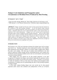
Ultra Nanoindentation Tester (0 - 50 mN)<br />
The Ultra Nanoindentation tester is uniquely configured as two indenter columns in parallel. One uses the indentation<br />
tip, the other has a large radius of curvature as a reference probe. Each has its own load cell. The two are connected<br />
together very near the sample surface with a differential capacitive sensor measuring the difference in the positions of<br />
the two tips. Thus, the indentation tip is always referenced to a position on the sample surface.<br />
//// Features<br />
> Active top referencing (Patented Design)<br />
The reference is removable and can be of different shapes (ball, pin, etc). The reference has its own<br />
piezo actuator and load sensor. It applies a very small feedback loop control load on the sample.<br />
> Thermal drift free<br />
The head is constructed out of ZeroDur® glass and the electronics system has a raw drift rate of < 1ppm/°C<br />
> Highest load frame stiffness<br />
By use of a synthetic granite frame, ZeroDur and the patented active top referencing system, frame<br />
compliance is kept at an absolute minimum.<br />
> Two independent depth and load sensors<br />
Ultra high resolution capacitive sensors for True Depth and Load Control modes.<br />
> Ultra high resolution and very low noise floor<br />
Depth resolution: 0.001 nm, noise floor < 0.1nm<br />
Force resolution: 0.01 μN, noise floor < 0.5μN<br />
//// Options<br />
> Vacuum or environmental enclosure<br />
> Atomic Force Microscope<br />
> High resolution table<br />
> High resolution camera<br />
> Protective acoustic enclosure<br />
Open Platform with<br />
Ultra Nanoindentation, Nano Scratch,<br />
AFM and optical video module<br />
7
Nanoindentation Tester (0 - 500 mN)<br />
The Nanoindentation Tester is designed to provide low loads with depth measurements in the nanometer scale. The<br />
system can be used to characterize organic, inorganic, hard and soft materials.<br />
//// Features<br />
> Top referencing of the sample surface<br />
> Synthetic granite frame for high frame stiffness<br />
> Automated video microscope for inspection both pre- and post-test<br />
> Feedback control of normal force<br />
> Complies with ISO 14577 and A<strong>ST</strong>M E2546<br />
//// Options<br />
> Vacuum or Environmental control<br />
> Atomic Force Microscope<br />
> High resolution camera<br />
> High resolution table<br />
//// Table Top Platform<br />
Developed specifically for our Nanoindentation tester, the <strong>CSM</strong> Table Top Instrument combines all the advantages of the<br />
standard Nanoindentation Tester (NHT) into a small and simple-to-use instrument which is ideally suited to routine nanoindentation<br />
testing where a full platform system may not be appropriate or necessary.<br />
The Table Top instrument has the advantage of being extremely compact and specifically designed for mechanical hardness<br />
testing. It can be configured with different motorized or manual tables in order to match restricted budgets. The Table Top<br />
instrument therefore provides a cost-effective solution, whilst maintaining the great technical features of the original <strong>CSM</strong><br />
nanoindentation technique.<br />
//// Micro Indentation Tester (0 - 30 N)<br />
The Micro Indentation Tester is ideally suited to the measurement of thin hard coatings, thick soft coatings and bulk<br />
materials. It provides accurate and reproducible values for hardness and elastic modulus determination of materials.<br />
The Micro Indentation Tester can be used for bulk materials and coatings such as PVD and CVD hard coatings and<br />
ceramic surface layers.<br />
//// Features<br />
> Automated video microscope<br />
> Feedback control of normal force<br />
> Unique top referencing method<br />
//// Options<br />
> ConScan objective<br />
> Temperature controlled stage (-120° - 450°C)<br />
> High resolution camera<br />
8
Indentation Software<br />
Full software package for data acquisition and analysis including:<br />
//// Measurement modes<br />
> Complete control of indentation parameters<br />
> Real time display of force and depth data during acquisition<br />
> Fully user definable indentation modes<br />
> Sinus mode (with Nanoindentation only)<br />
> Full user access rights management<br />
> Automated indenter tip calibration<br />
> Automated positioning correlation between indentation and imaging analysis<br />
> Full integration of AFM and Video imaging into the indenter control software<br />
> MultiFocus Imaging<br />
//// Data analysis<br />
> Powerful, fully integrated statistics module (data and graphics tools)<br />
> Automated measurement report generator<br />
> Logging of all operations executed on the instrument<br />
> Multi language support<br />
> Data export in ASCII format. Open files with Excel or text editor<br />
//// Mechanical properties results<br />
> Automatic calculation of Hardness (H IT<br />
), Elastic Modulus (E IT<br />
),<br />
recalculated Vickers (Hv), Creep (C IT<br />
), Relaxation (R IT<br />
)<br />
> Display of all nanoindentation data results : hm, hc, ...<br />
> Display of Hardness and Elastic Modulus vs. Depth<br />
> Multiple models for hardness and elastic modulus evaluation<br />
> Standard evaluation according to ISO 14577 and A<strong>ST</strong>M E2546<br />
//// Possible additional analysis for specific material properties<br />
> Analysis of fracture toughness, creep and stress-strain behavior<br />
> Analysis of plastic-elastic energy work<br />
> Storage Modulus and Loss Modulus calculation for viscoelastic materials<br />
(with Sinus mode option only)<br />
> Also included: Material deformation modelling software<br />
//// Accessories and Consumables<br />
> Various indenter geometries (Berkovich, Vickers, Cube Corner, Spherical,...etc.)<br />
> Vacuum, humidity and temperature controlled options<br />
> ISO 14577 parts (all parts certified following the ISO requirements)<br />
Please contact us to discuss your specific applications<br />
9
SCRATCH TE<strong>ST</strong>ERS<br />
For Adhesion and Scratch Resistance<br />
//// Features of the Scratch Testers<br />
> Proven method to quantify adhesion of<br />
coatings<br />
> Acoustic Emission, Friction, Penetration Depth<br />
and optical observation<br />
> Feedback control of normal force<br />
> Patented panorama image<br />
> Characterization of large (300 mm) samples<br />
> Wear testing in multipass mode<br />
> Automated video microscope inspection<br />
> Automated, unattended multi sample testing<br />
> ISO and A<strong>ST</strong>M compliance<br />
//// Introduction to the Scratch Testers<br />
The <strong>CSM</strong> Scratch Testers are ideal instruments<br />
for characterizing the surface mechanical properties<br />
of thin films and coatings, e.g. adhesion,<br />
fracture and deformation.<br />
They can be used for all kinds of industrial coatings<br />
from the plasma processed layers used in<br />
semiconductor and optical technology to the<br />
decorative and protective coatings used for<br />
consumer goods and automobile parts.<br />
The scratch tester’s ability to characterize the<br />
film - substrate system and to quantify parameters<br />
such as friction force and adhesive strength,<br />
using a variety of complementary methods,<br />
makes it an invaluable tool for research, development<br />
and quality control.<br />
The technique involves generating a controlled<br />
scratch with a diamond tip on the sample under<br />
test. The tip is drawn across the coated surface<br />
under constant, incremental or progressive<br />
load.<br />
At a certain critical load the coating will start to<br />
fail. The critical loads are very precisely detected<br />
by means of the frictional coefficient, the penetration<br />
depth, the acoustic emission sensor together<br />
with observations from a built-in optical<br />
microscope.<br />
The critical load data is used to quantify the<br />
adhesive properties of different film - substrate<br />
combinations by using different sensors (acous-<br />
tic emission, penetration depth, friction force)<br />
and video microscope observations.<br />
//// Active Force Feedback Loop Control<br />
Force feedback is now available on many instruments<br />
but the unique design of the <strong>CSM</strong> control<br />
unit allows an active force feedback which<br />
is controlled electronically and not corrected by<br />
the software. The unique design of the Nano<br />
Scratch measurement head includes force and<br />
depth sensors associated with a state-of-theart<br />
piezoelectric sensor. These unique features<br />
provide fast response time (down to 5 milliseconds),<br />
greater accuracy and greater flexibility<br />
for all types of scratch measurement.<br />
//// Video Microscope & dual screen PC<br />
Scratch Testers are delivered with an integrated<br />
video microscope. Standard available objectives<br />
are x5, x20, x50 or x100 leading to a total magnification<br />
ranging from x200 to x4000.<br />
Two video cameras are available: the standard<br />
model with a resolution of 768 x 582 or the<br />
optional high resolution 1280 x 1024 model using<br />
a progressive scan sensor with a very high<br />
sensitivity.<br />
In addition a LCD dual screen PC is delivered<br />
enabling a simultaneous and synchronised view<br />
of the scratch data and images.<br />
//// Patented Panorama capture<br />
<strong>CSM</strong> Panorama mode digitally stitches together<br />
multiple images along the length of the scratch<br />
to generate a panoramic view of the entire<br />
scratch. This view is synchronized with the data<br />
below it. As you scroll laterally through the<br />
data, a cursor tracks the position in the scratch<br />
track.<br />
10
Nano Scratch Tester (0 - 1000 mN)<br />
The Nano Scratch Tester is particularly suited for the characterization of the practical adhesion failure of thin<br />
films and coatings, with a typical thickness below 1000 nm.<br />
The Nano Scratch Tester can be used in the analysis of organic and inorganic coatings as well as soft and hard<br />
coatings.<br />
//// Features<br />
> Diamond-stylus scratch method<br />
> Automated video microscope<br />
> Active force feedback loop control (by a state-of-the-art actuator)<br />
> Scratch depth measurement with both pre and post scratch scan corrections<br />
> Compatible to A<strong>ST</strong>M D7187<br />
//// Options<br />
> Nanoindentation and Micro Indentation measurement modules<br />
> Vacuum, humidity and temperature controlled<br />
> AFM and ConScan 3D imaging<br />
> High resolution table<br />
> High resolution camera<br />
> Swinging module<br />
> Acoustic enclosure<br />
11
Micro Scratch Tester (0 - 30 N)<br />
The Micro Scratch Tester is widely used to characterize the practical adhesion failure of thin films and coatings, with<br />
a typical thickness below 5 μm. The Micro Scratch Tester is also used in the analysis of organic and inorganic soft<br />
and hard coatings.<br />
//// Features<br />
> Diamond-stylus scratch method<br />
> Automated video microscope<br />
> Feedback controlled normal force<br />
> Scratch depth measurement with both pre and post scratch scan corrections<br />
> Surface profiling<br />
> Acoustic emission sensor<br />
//// Options<br />
> Swinging mode<br />
> High resolution Video,<br />
> AFM or ConScan 3D imaging<br />
> Wide range of indenter tips<br />
> Indentation option<br />
> Temperature controlled stage<br />
//// Revetest © Macro Scratch Tester (0 - 200 N)<br />
The REVETE<strong>ST</strong> ® Scratch Testing instrument is widely used for characterizing hard-coated materials, with a typical<br />
coating thickness exceeding 1 μm.<br />
With more than 1500 Revetest systems sold worldwide, <strong>CSM</strong> is the world leader in scratch testing.<br />
//// Features<br />
> Diamond-stylus scratch method<br />
> Feedback controlled normal force<br />
> Acoustic emission detection<br />
> Video microscope<br />
> Long term stability of calibration<br />
> Complies with A<strong>ST</strong>M C1624, ISO 20502 and EN 1071<br />
//// Options<br />
> Verification kit for load, friction force and penetration depth<br />
> High resolution Video camera<br />
> Wide range of indenter tips<br />
12
Scratch Software<br />
Full software package for data acquisition and analysis including:<br />
//// Complete measurement modes<br />
> Unique patented panorama mode<br />
> MultiFocus Image<br />
> Real time display of force and depth data during acquisition<br />
> Fully user definable scratch modes<br />
Single and multiple scratches; constant, incremental or progressive<br />
loads; user-defined load profiles, ... etc.<br />
> Large range of testing modes: scratch, wear, indentation<br />
> System setting programmable for every single scratch in a multiscratch<br />
experiment<br />
> Fully customized user access rights management<br />
> Automated positioning between the tip and imaging module<br />
> Full integration of AFM and Video imaging into the same software (for<br />
Nano and Micro Scratch Testers)<br />
> Multi language support<br />
//// Data analysis<br />
> Critical loads, Lc, as a function of normal loads<br />
> Powerful and fully integrated statistical module (data and graphics)<br />
> Automatic measurement report generator with unlimited templates<br />
> Logging of all operations executed on the instrument<br />
> Data export in ASCII format. Open files with Excel or text editor<br />
> Material deformation modeling software<br />
//// Accessories and Consumables<br />
> Various indenter geometries (knife, spherical, blade, etc...)<br />
> Vacuum, humidity and temperature controlled options<br />
> ISO 20502 parts (all certified per ISO requirements)<br />
Please contact us with your requirements<br />
13
BALL/PIN-ON-DISK TRIBOMETER<br />
For Friction Coefficient and Wear Resistance<br />
//// Features of the <strong>CSM</strong> Tribometers<br />
> High Resolution attained with unique<br />
frictionless force sensor design<br />
> Easy and automated calibration procedures<br />
> High-precision feedback controlled motor<br />
> Precisely calibrated instrument for friction<br />
> Linear and Rotating sample displacement<br />
> Sample Heating Option (up to 1000°C)<br />
> Automatic switch off at friction coefficient<br />
threshold or total number of cycles<br />
> Tests compliant to A<strong>ST</strong>M G99 & DIN 50324<br />
> Tests in liquids, controlled humidity or inert<br />
gases within Plexiglas enclosure<br />
//// Introduction to the <strong>CSM</strong> Tribometers<br />
In tribometry, a sphere, a pin or a flat section<br />
is loaded onto the test sample with a precisely<br />
known force. The probe is mounted on a stiff<br />
lever, designed as a frictionless force transducer.<br />
The friction coefficient is determined during the<br />
test by measuring the deflection of the elastic<br />
arm. Wear coefficients for the pin and disk materials<br />
are calculated from the volume of material<br />
lost during the test. This simple method<br />
facilitates the study of friction and wear behaviour<br />
of almost every solid material combination<br />
with or without lubricant. Furthermore, the<br />
control of the test parameters such as speed,<br />
frequency, contact pressure, time and environmental<br />
parameters (temperature, humidity and<br />
lubricant) allows simulation of the real life conditions<br />
of a practical wear situation.<br />
Tribometers are unique instruments designed<br />
for high precision force measurement. They<br />
operate in both linear recipricating and rotational<br />
modes. One important feature of all<br />
<strong>CSM</strong> Tribometers is that the experiment stops<br />
automatically when the coefficient of friction<br />
reaches a predefined threshold value or when<br />
a specified number of cycles is reached. Also,<br />
the tribometer is supplied with an enclosure so<br />
that controlled atmospheres of varying humidity<br />
or composition can be used. Specialized versions<br />
of the Tribometer have been developed<br />
for high and low temperature operation and<br />
testing in a high vacuum.<br />
//// Linear Reciprocating Tribometer<br />
The Linear Tribometer reproduces the reciprocating<br />
motion typical of many real world mechanisms.<br />
The instrument measures a friction<br />
coefficient for both the forward and backward<br />
displacement of the stroke and the software<br />
generates data on Hertzian pressure, static<br />
partner and sample wear rates. The reciprocating<br />
technique is also very useful for studying<br />
the variation over time of the static coefficient<br />
of friction - as opposed to the dynamic coefficient<br />
measured with the Pin-on-Disk configuration.<br />
Most contact geometries can be reproduced<br />
including Pin-on-Plate, Ball-on-Plate and<br />
Flat-on-Plate (others on request). The Linear Tribometer<br />
can be equipped with a heating and<br />
cooling plate for testing under a wide variety of<br />
temperatures.<br />
//// Vacuum Tribometers<br />
All <strong>CSM</strong> Tribometers are available in a high vacuum<br />
configuration. These fully automated instruments<br />
allow tribological testing under high<br />
vacuum conditions. Turbomolecular pumping<br />
produces a vacuum of 5 x 10 -7 mbar.<br />
//// Optional Compact Profilometer<br />
The Compact Profilometer is a very user-friendly<br />
tool, dedicated to fast and easy profile measurements<br />
of the sample track section created by<br />
the tribological tests.<br />
14
Pin-on-Disk Tribometer (0 - 60 N)<br />
The control of friction and wear in moving machine parts is a critical issue facing the manufacturing industry. It is<br />
important to have comparable analysis data obtained over a period of years, at varying humidity and temperature<br />
and in the presence of lubricants. <strong>CSM</strong> Tribometers have proven their reliability worldwide in over 1000 laboratories,<br />
for studying new materials, lubricants and oil additives for research or quality control.<br />
//// Features<br />
> Precisely calibrated friction and wear measurements<br />
> Stable contact point and no parasitic friction<br />
> Variable sample sizes and shapes<br />
> Test in liquids and controlled humidity<br />
> Testing compatible with ISO and A<strong>ST</strong>M<br />
//// Options<br />
> Electrical contact resistance<br />
> Reciprocating (Linear mode)<br />
> Liquid heating<br />
> Continuous wear depth measurement<br />
> Compact profilometer Co<br />
> Vacuum setup<br />
Standard Tribometer<br />
//// High Temperature Tribometer (up to 1000°C)<br />
The analysis of friction and wear properties of materials at elevated temperatures is becoming increasingly important,<br />
especially for the development and quality control of combustion engines and power plants. To meet the resulting<br />
demand for instrumentation, <strong>CSM</strong> <strong>Instruments</strong> has extended its range of pin-on-disk Tribometers with a powerful<br />
high-temperature version which can accurately simulate in-service conditions.<br />
//// Features<br />
> Precisely calibrated friction and wear measurements at elevated temperatures up to 1000°C<br />
> Efficient heating/cooling system to accurately maintain desired test temperature<br />
> High thermal stability<br />
> Automatic shut-off at selected track length or friction coefficient threshold<br />
> Testing conforms to DIN 50324, A<strong>ST</strong>M G99 and A<strong>ST</strong>M G133.<br />
> Differential friction sensors for perfect stability of friction measurements at all temperatures<br />
.<br />
//// Options<br />
> Electrical contact resistance<br />
> Multi-Cycle Reciprocating<br />
> Continuous wear depth measurement<br />
> Vacuum setup<br />
15
Nano Tribometer (0 - 1000 mN)<br />
The <strong>CSM</strong> Nano Tribometer has been designed specifically to investigate the surface interactions at low contact pressures,<br />
especially where soft layers or lubricants are of interest. This instrument allows significant contact areas to be<br />
investigated, whilst maintaining a high accuracy and measurement of very low forces and displacements.<br />
The Nano Tribometer is based on a stiff cantilever, which acts as a frictionless force transducer in both vertical and<br />
horizontal directions. The static partner (flat/pin/sphere) is loaded onto the test sample with a precisely known force<br />
using piezo-actuation. The friction coefficient is determined during the test by measuring the deflection of this elastic<br />
arm in both horizontal and vertical planes with two high precision displacement sensors. Through a feedback loop, the<br />
piezo-actuation maintains the normal load independent of any surface irregularities.<br />
This Nano Tribometer is a unique instrument because of its low load range down to 50 μN. It can perform both linear<br />
reciprocating and rotating actuation.<br />
//// Features<br />
> Ultra low contact pressures<br />
> Patented Cantilever for Nano-friction Measurements<br />
> Normal and lateral forces decoupled<br />
> Continuous wear depth measurement<br />
> Easy calibration<br />
> Ultra-high precision piezo actuated motion<br />
> Linear and/or rotating sample displacement<br />
> Test in liquids and in controlled humidity or inert gases with plexiglas enclosure<br />
> Conforms to ISO and A<strong>ST</strong>M Standards<br />
//// Options<br />
> Sample heating option<br />
> Various force spring cantilevers<br />
> Vacuum or environmental enclosure<br />
16
Tribometer Software<br />
Full software package for data acquisition and analysis including:<br />
//// Complete measurement modes<br />
> Continuous real time data acquisition of friction (Ft) signal during a test<br />
> Tangential force Ft sampling rate: adjustable frequency in Hz<br />
> Automatic generation of reports for a set of measurements<br />
> Temperature control via software<br />
> Automatic calibrating procedures:<br />
- Force measurement calibration<br />
- Speed calibration<br />
- Radius calibration<br />
> First lap synchronization:<br />
- each test can be started at the same position of the circle<br />
> Advanced measurement settings<br />
- Setup and configuration of tribometer experiments<br />
//// Data analysis<br />
> Friction force, sliding lifetime behaviour<br />
> Autocalculation of sample wear rate and ball wear rate<br />
> Powerful and fully integrated statistical module (data and graphics)<br />
> Automatic measurement report generator<br />
> Data export in ASCII format. Open files with Excel or text editor<br />
> Material deformation modeling software<br />
//// Accessories and Consumables<br />
> Vacuum setup<br />
> Differents ball materials (Alumina, Silicon Nitride, Hard Metals,<br />
100Cr6 Steel, Ruby, Sapphire, etc...)<br />
> Container for liquid testing (with or without temperature control)<br />
> Weights (0.25, 0.5, 1, 2, 5, 10, 20, 30 and 60 N)<br />
Please contact us with your specific needs<br />
17
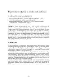
CALOTE<strong>ST</strong><br />
For Coating Thickness Measurement<br />
Diamond slurry<br />
//// Calotest principle<br />
Sphere<br />
Drive shaft<br />
The Calotest provides quick, simple and inexpensive<br />
determination of coating thicknesses.<br />
A rotating sphere with a known diameter is<br />
pressed on the coating surface with a preselected<br />
load. Both the position of the sphere relative<br />
to the center of the sample and the contact<br />
load are constant. Upon adding abrasive<br />
slurry to the contact zone, a depression with<br />
the shape of a spherical depression is abraded<br />
into both the coating and the substrate.<br />
Optical inspection of the depression reveals the<br />
projected surfaces of the abraded coating and<br />
substrate sections. By measuring X and Y, the<br />
thickness of the coating, D, can be calculated<br />
by simple geometry.<br />
The <strong>CSM</strong> Calotest Platform produces under a vacuum three-body wear system.<br />
Micro As a steel Combi ball Tester rolls and on the Optical surface Microscope of the<br />
sample, a slurry consisting of water and fine<br />
abrasive particles drips continuously onto the<br />
ball at the contact region. The slurry wears the<br />
substrate in a controlled manner and thus assures<br />
highly reproducible results.<br />
D<br />
X<br />
Thickness = D =<br />
Y<br />
X x Y<br />
ball diameter<br />
X<br />
Y<br />
Compact Calotest<br />
18
Calotest<br />
The CALOTE<strong>ST</strong>® is widely used for analyzing coatings with thicknesses of between 0.1 and 50 μm. The simple ballcratering<br />
method is a fast and accurate mean of checking the thickness of any coating, whether a single or multilayered<br />
stack. Typical examples include CVD, PVD, plasma spray coatings, anodic oxidation layers, surfaces treated<br />
by ion sputtering or ion plating, chemical and galvanic deposits, polymers, paints and lacquers.<br />
//// Features<br />
> Spherical abrasion test method<br />
> Determination of coating thickness<br />
> Applicable to a wide variety of materials<br />
> Fine and extra fine polishing slurries<br />
//// Options<br />
> Optical measuring system<br />
Industrial Calotestt<br />
19
3D IMAGING<br />
Atomic Force Microsope (AFM)<br />
//// Features of the <strong>CSM</strong> AFM<br />
> Fast and easy localization of structures with<br />
our video microscope<br />
> Different scan ranges available<br />
(up to 200 μm x 200 μm)<br />
> Liquid compatible<br />
> Conveniently switches among all SPM<br />
modes<br />
> No mechanical adjustments after tip<br />
changes<br />
> Ease-of-use<br />
> Accurate translation of the area of interest<br />
to under the AFM tip<br />
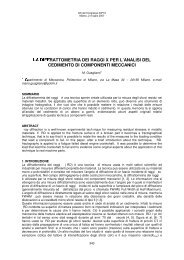
//// AFM principle<br />
Atomic force, or scanning probe microscopy<br />
(AFM, SPM), is an extremely accurate and versatile<br />
technique for measuring structures or<br />
surface forces. A very fine sensor tip mounted<br />
to the end of a small deflecting spring - known<br />
as a cantilever - is brought into contact with the<br />
sample surface to be investigated.<br />
The sensor tip is then moved across the surface<br />
in numerous line scans. Due to the surface<br />
roughness (topography), the tip and cantilever<br />
move up and down. This movement can be<br />
measured with high resolution and the resulting<br />
data allows imaging the surface structure.<br />
Fig 2. General principles of surface scanning<br />
Fig 1. General principles of the AFM<br />
The deflection of the cantilever is measured by<br />
an incident laser beam. One part of the incident<br />
laser beam is reflected on the fiber end<br />
while the other part is reflected on the cantilever.<br />
The optical path difference between the<br />
two reflected beams provides the accurate distance<br />
measurement used by the Atomic Force<br />
Microscope for the nanometer-scale image.<br />
Fig 3. Interferometer principle<br />
20
Atomic Force Microscope<br />
Atomic Force Microscope, or Scanning Probe Microscopy (AFM, SPM), is an extremely accurate and versatile technique<br />
for measuring surface topography at the nanoscale. A very fine sensor tip mounted to the end of a small deflecting<br />
cantilever is brought into contact with the sample surface to be investigated. The sensor tip is moved across the surface<br />
in numerous line scans, which produce a three-dimensional image of the surface with ultra high resolution. This<br />
technique is especially useful for imaging residual scratches, indentations or other nanoscale surface features as well<br />
as accurately measuring their dimensions.<br />
//// Features<br />
> The combination of optical and Scanning Probe Microscopy (SPM) opens up new possibilities in<br />
quantitative visual surface characterization<br />
> Optical inspection of large sample areas with the ability to zoom in on interesting structures with<br />
sub-nanometer resolution<br />
> Analysis of micro or nanostructures<br />
> Critical Dimension (CD) measurements<br />
> Investigation of etched structures and roughness<br />
> Profile analysis of coatings and thin films<br />
> Measurements of surfaces with low optical contrast<br />
> Characterization of fragile biological tissue as well as many other applications in materials<br />
and surface research<br />
//// Options<br />
> Non - contact, intermittent, and close - contact mode, including phase contrast<br />
> Frequency detection mode, including Q - Factor Control<br />
> Field contrast modes (magnetic force, electrostatic force mode, MFM / EFM) for simultaneous imaging of<br />
long ranging interactions<br />
> Force modulation mode (variable force applied to the tip) for measurements of elastic properties<br />
> Lateral force mode, friction measurement<br />
> Surface potential mode (Kelvin probe), for work function measurements<br />
> <strong>ST</strong>M - Scanning Tunneling Microscopy<br />
> Spreading Resistance for measurements of resistance and conductivity<br />
> Measurements in liquids<br />
21
3D IMAGING<br />
ConScan Objective<br />
//// Features of the <strong>CSM</strong> ConScan Objective<br />
> ConScan chromatic image provides a noncontact<br />
topographical 3D view<br />
> No sample preparation required<br />
> In situ, fast real time measurements on all<br />
types of materials and surfaces<br />
> Totally passive optical pen : no mechanical<br />
part in motion in the optical pen<br />
> Interchangeable optical pen allowing different<br />
measuring range and axial resolution<br />
> Large range of XY scanning<br />
(using X and Y instrument table)<br />
> Profile measurement (direct or extracted)<br />
> Create 2-D and 3-D images<br />
> Perform measurements on transparent<br />
surfaces<br />
> Image surface defects and testing deformations<br />
//// ConScan principle<br />
> White light ConScan Imaging<br />
ConScan imaging consists of taking polychromatic,<br />
white light, and passing it through a<br />
chromatic lens normally incident to the sample.<br />
This lens is specifically designed to have a wide<br />
variation of refractive indices for differing wavelengths<br />
of light. This effect thus produces a focal<br />
point that varies spatially in the Z direction<br />
to the wavelength. A pinhole type spatial filter<br />
insures that only the light that is in focus at a<br />
specific Z height will reach the detector. This<br />
detector is actually a spectrometer and records<br />
the wavelength of the incoming signal.<br />
This wavelength is accurately correlated to the<br />
chromatically dispersed focal point in space and<br />
hence to the height of the sample area which<br />
reflected it.<br />
Therefore, the resultant spectrum can be regarded<br />
as a spectrophotometric signature of<br />
the material surface; spectral peaks represent<br />
the “height” of the sample at that focus point.<br />
The system scans over the surface of the sample,<br />
creating these spectral height signatures at<br />
sub-micron intervals, summating to an overall<br />
image with axial accuracy in the nanometer<br />
range.<br />
> Image acquisition<br />
A single-point white light source directs polychromatic<br />
light through a filter towards the<br />
sample surface.<br />
The light then passes through a perfect chromatic<br />
lens which separates the white light into<br />
its component bands. Each wavelength is represented<br />
along the optical axis at a unique position<br />
from the lens.<br />
The wavelength-coded light bounces off the<br />
sample surface and travels through a pinhole to<br />
the spectrometer.<br />
The spectrum result is correlated to the height<br />
of the sample at that point.<br />
Using the system tables, the sample is moved<br />
under the scanning objective to produce an image<br />
of the entire surface.<br />
Measurement space<br />
S<br />
Source of<br />
white light<br />
Unadjusted<br />
axial<br />
colour range<br />
objective<br />
A 1 A 2 A i An<br />
Monochromatic picture<br />
continuum<br />
22
ConScan Objective<br />
The ConScan objective opens up new possibilities in quantitative 3D topographical imaging in the range of a few<br />
microns to hundreds of microns of Z-axis variation of the sample surface. It is the perfect addition to a <strong>CSM</strong> Platform<br />
testing system, especially for the topographic analysis of <strong>CSM</strong>’s micro-range indentation imprints and scratch tracks.<br />
By scanning the sample surface in the X-Y directions, the ConScan provides the micro-topographic structure of any<br />
type of surface (rough as well as polished) for any type of material. This includes glossy, matte, transparent and opaque<br />
materials, which can prove extremely difficult to image with other conventional imaging systems.<br />
//// Features<br />
> Ideal addition to <strong>CSM</strong> <strong>Instruments</strong> micro-range products for analyzing the 3D topography<br />
of micro-scratches and micro-indentations<br />
> Non-contact measurement<br />
> Large XY scanning range (using instrument’s XY tables)<br />
> High Z-axis dynamic range (up to 400 microns)<br />
> Accurate measurement of 2D profiles, 3D topography and surface roughness<br />
> Ability to perform measurements on transparent surfaces<br />
> Measurement of rough or polished surfaces<br />
> Wide range of objectives for different height ranges<br />
//// Options<br />
> Six different chromatic lenses (ranging from 100 μm to 24 mm depth of field).<br />
//// Example of a scratch analysis<br />
Acquisition / topography Measurement of profiles 3D imaging of the full scratch<br />
//// Other applications<br />
Profilometry<br />
Microtopography<br />
Roughness<br />
measurement<br />
Autofocus<br />
Vibrometry<br />
In-line inspection<br />
Quality control<br />
In-line inspection<br />
Quality control<br />
23
SPECIAL IN<strong>ST</strong>RUMENTS<br />
Mechanical Characterization Under Vacuum<br />
//// Mechanical Characterization<br />
Under Vacuum<br />
Mechanical properties can be highly dependent<br />
on environmental conditions such as pressure,<br />
temperature and gases present. <strong>CSM</strong> <strong>Instruments</strong><br />
has developed a full range of environmental<br />
control options. The most discriminating<br />
applications require the investigation of the<br />
influence of these parameters on materials and<br />
real-world end products.<br />
<strong>CSM</strong> <strong>Instruments</strong> has developed special versions<br />
of our conventional instrumentation for<br />
use in high and medium-vacuum conditions.<br />
Applications such as aerospace, military defense,<br />
micro-electronics, MEMS devices, and the<br />
automotive often require high vacuum for realistic<br />
measurements. Medium vacuum is also<br />
regularly used in combination with temperature-controlled<br />
analysis in order to reduce the<br />
amount of oxidation occurring.<br />
//// Vacuum Platform<br />
> Our automated Platform Systems, equipped<br />
with Nano or Micro-scale Indentation or<br />
Scratch Tester modules can be integrated with<br />
vacuum control in both the high-vacuum (to<br />
10 -7 mbar) and medium-vacuum ranges. The<br />
medium-vacuum configuration can also be<br />
used with a heating stage for sample temperature<br />
control up to 450°C.<br />
The <strong>CSM</strong> medium-vacuum module is designed<br />
to comply with the modular design of <strong>CSM</strong><br />
Compact Platform instrument series. This allows<br />
adaptation of a wide range of <strong>CSM</strong> sensor<br />
heads for measuring under primary vacuum<br />
conditions.<br />
//// High Vacuum<br />
Tribometer<br />
> The vacuum Tribometer is<br />
used to determine the sliding<br />
life of self-lubricating<br />
coatings as well as friction<br />
and wear behavior of bulk<br />
materials or protective coatings<br />
by varying the contact<br />
pressure, lateral velocity and<br />
temperature while under<br />
vacuum conditions. The system<br />
can reach a pressure of<br />
10 -7 mbar.<br />
<strong>CSM</strong> Platform under vacuum<br />
Micro Combi Tester and Optical Microscope<br />
24
Mechanical Characterization Using Temperature and<br />
Humidity Control<br />
Mechanical properties can also be affected by the temperature<br />
and humidity of the surrounding environment. In order<br />
to study the influence of these parameters on the material<br />
of interest or to investigate material behavior under precise<br />
environmental conditions, <strong>CSM</strong> has created integrated solutions<br />
for use with our wide range of high-performance mechanical<br />
testing instruments.<br />
Civil engineering applications like geomaterials, natural composites,<br />
cement pastes, concrete, shales, clay, sandstone, tobermorite<br />
are highly affected by temperature and humidity.<br />
Similarly, metallic composites having a complex heterogeneous<br />
structure, polymeric materials, microelectronics and<br />
Nanoindentation under temperature and humidity control<br />
Temperature and humidity-controlled chamber<br />
semiconductor usually require temperature and humidity<br />
control in order to understand the structural role of<br />
water and temperature.<br />
Nano or Micro Indentation or Scratch Testers, configured<br />
within a temperature and humidity control chamber, can<br />
reach a humidity range of 20-95% RH and a temperature<br />
range of 10-40°C. The solution provided by <strong>CSM</strong><br />
<strong>Instruments</strong> allows material mechanical properties measurement<br />
“in-vivo”, with fully-integrated control of various<br />
environmental conditions.<br />
Contact us for more information<br />
25
INTERNATIONAL <strong>ST</strong>ANDARDS<br />
//// Indentation Testing:<br />
ISO 14577<br />
ISO 6508<br />
ISO 6507<br />
ISO 4516<br />
Metallic materials – Instrumented indentation test for hardness and material<br />
parameters<br />
Metallic materials – Rockwell hardness test<br />
Metallic materials – Vickers hardness test<br />
Metallic and related coatings – Vickers and Knoop micro hardness tests<br />
DIN 50359<br />
DIN 55676<br />
Testing of metallic materials – Universal hardness test<br />
Paint and varnishes – Universal hardness of coatings<br />
A<strong>ST</strong>M E2546<br />
A<strong>ST</strong>M B933<br />
A<strong>ST</strong>M D785<br />
A<strong>ST</strong>M E140<br />
A<strong>ST</strong>M E384<br />
A<strong>ST</strong>M B578<br />
New standard practice for instrumented indentation testing<br />
Standard test method for micro indentation hardness of powder metallurgy<br />
materials<br />
Standard test method for Rockwell hardness of plastics and electrical insulating<br />
materials<br />
Standard hardness conversion tables for metals<br />
Standard test method for micro hardness of materials<br />
Standard test method for micro hardness of electroplated coatings<br />
JIS B7734<br />
JIS R1607<br />
JIS Z2255<br />
Knoop hardness test – Verification of testing machines<br />
Testing methods for fracture toughness of high performance ceramics<br />
Method for ultra-low load hardness test<br />
SAE J417<br />
Hardness tests and hardness number conversions<br />
//// Scratch Testing:<br />
ISO 20502<br />
ISO 1518<br />
Fine ceramics – determination of adhesion of ceramic coatings by scratch testing<br />
Paints and varnishes – scratch test<br />
DIN EN1071<br />
Advanced technical ceramics – method of test for ceramic coatings<br />
A<strong>ST</strong>M C1624<br />
A<strong>ST</strong>M D7187<br />
Standard test method for adhesion strength and mechanical failure modes of<br />
ceramic coatings by quantitative scratch testing<br />
Scratch/Mar behavior of paint coatings<br />
26
A<strong>ST</strong>M D7027<br />
Evaluation of scratch resistance of polymeric coatings and plastics using an instrumented<br />
scratch machine<br />
JIS R3255<br />
Test methods for adhesion of thin films on glass substrates<br />
//// Tribology Testing:<br />
ISO 20808<br />
Determination of friction and wear characteristics of monolithic ceramics by ball-on-disc<br />
method<br />
DIN 50324 Tribology; testing of friction and wear model test for sliding friction of solids<br />
(ball-on-disc system)<br />
DIN 51834 Testing of Lubricants - Tribological Test in the translatory oscillation apparatus -<br />
Part 1: General Working Principles<br />
A<strong>ST</strong>M G 99<br />
A<strong>ST</strong>M G 133<br />
Standard test method for wear testing with a pin-on-disk apparatus<br />
Standard test method for linear reciprocating Ball-on-flat sliding wear<br />
//// Calotest and Calowear Testing:<br />
ISO EN-1071<br />
Determination of the abrasion resistance of coatings by a micro-abrasion wear test<br />
VDI 3198<br />
Thickness of cold forging tool coatings (PVD, CVD)<br />
27
Location of <strong>CSM</strong> <strong>Instruments</strong><br />
//// <strong>CSM</strong> <strong>Instruments</strong> SA<br />
Rue de la Gare 4<br />
Galileo Center<br />
CH-2034 Peseux<br />
Switzerland<br />
info@csm-instruments.com<br />
T : +41 32 557 5600<br />
F : +41 32 557 56 10<br />
//// <strong>CSM</strong> <strong>Instruments</strong>, Inc.<br />
197 1st Ave, suite 120<br />
Needham, MA-02494<br />
United States<br />
usinfo@csm-instruments.com<br />
T : (781) 444-2250<br />
F : (781) 444-2251<br />
//// <strong>CSM</strong> <strong>Instruments</strong> Germany<br />
Basler Strasse 115<br />
79115 Freiburg<br />
Germany<br />
deinfo@csm-instruments.com<br />
T : +49 7 61 47 87 150<br />
F : +49 7 61 47 87 100<br />
//// <strong>CSM</strong> <strong>Instruments</strong> China<br />
1518 15th floor NCI Tower<br />
12A, Jianguomenwai Ave<br />
Chaoyang District, Beijing 100022<br />
China<br />
cninfo@csm-instruments.com<br />
T : +86 10 8523 3119<br />
F : +86 10 8523 3001<br />
28