Ohne Titel 1
Ohne Titel 1
Ohne Titel 1

Create successful ePaper yourself
Turn your PDF publications into a flip-book with our unique Google optimized e-Paper software.
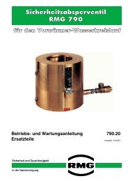
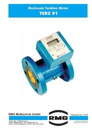
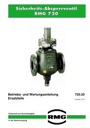
Safety Shut-Off Valve<br />
DN 25 - 150<br />
General Description 711.00<br />
edition 04/2000<br />
Serving the Gas Industry - WORLDWIDE
Safety Shut-Off Valve<br />
Application<br />
l<br />
l<br />
safety device for gas pressure regulating stations<br />
suitable for gases according to G 260 and all non-corrosive gaseous media<br />
Characteristics<br />
l easy maintenance, easy replacement of internal parts without dismantling the main valve from the line<br />
l switch device self-adjusting to zero position<br />
l integrated special safety by-pass valve for pressure compensation with automatic resetting into service position<br />
l low pressure drop due to in-line flow<br />
l four tripping facilities; manual release as a standard feature<br />
l electro-magnetic release and electric remote indication of valve position as special features<br />
l high response accuracy and short response time<br />
l same face to face dimensions as safety shut-off valve RMG 710<br />
1. Technical data<br />
maximum service pressure p max<br />
sizes<br />
connections<br />
valve seat diameter<br />
100 bar (depending on flange rating)<br />
DN 25, DN 50, DN 80, DN 100, DN 150<br />
flanges according to DIN PN 25 and PN 40, and ANSI 300, ANSI 600<br />
equal to pipe size diameter<br />
materials<br />
ambient temperature range<br />
main valve body<br />
switching device<br />
measuring unit<br />
internal parts<br />
diaphragms, o-rings<br />
closing spring<br />
-15°C to +60°C<br />
cast steel, steel<br />
cast aluminium<br />
aluminium forging alloy<br />
aluminium, stainless steel, brass, steel<br />
rubber-like plastic material<br />
stainless steel<br />
response time<br />
function and strength<br />
DIN-DVGW registration no.<br />
0,1 ... 0,3 s (depending on service pressure, valve size and control unit)<br />
according to DIN 3381<br />
valid for all sizes: NG-4303AL0136<br />
2
Safety Shut-Off Valve<br />
Adjustable ranges<br />
control<br />
element<br />
K 10a<br />
1<br />
2<br />
3<br />
4<br />
5<br />
setpoint spring<br />
Nr . colour<br />
bright red 3,2<br />
dark red 3,6<br />
white 4,75<br />
white<br />
black<br />
wire<br />
dia.Ø<br />
mm<br />
1,2<br />
1,4<br />
overpressure release<br />
minimum differential<br />
between response<br />
range pressure and<br />
service pressure<br />
W ho (bar) ∆p (bar)<br />
0,08 …0,25<br />
0,2 …0,5<br />
0,4 …1,5<br />
0,05<br />
0,10<br />
0,25<br />
underpressure release<br />
minimum differential<br />
between response<br />
pressure and<br />
service pressure<br />
W hu (bar) ∆p (bar)<br />
0,01 ...0,04<br />
0,035...0,12<br />
0,03<br />
0,06<br />
minimum differential<br />
between over-/<br />
underpressure<br />
response points<br />
with spring no.<br />
4 5 6<br />
0,09<br />
0,15<br />
0,30<br />
0,13<br />
0,18<br />
0,34<br />
response<br />
precision<br />
category<br />
AG*<br />
10 / 5<br />
5 / 2,5<br />
5 / 2,5<br />
15 / 5<br />
5<br />
K 11a/1<br />
1<br />
2<br />
3<br />
4<br />
5<br />
6<br />
bright red 3,2<br />
dark red 3,6<br />
white 4,75<br />
light blue<br />
black<br />
red<br />
1,1<br />
1,4<br />
2,25<br />
0,4 ... 0,8<br />
0,6 ... 1,6<br />
1,5 ... 4,5<br />
0,1<br />
0,2<br />
0,3<br />
0,06...0,15<br />
0,12...0,40<br />
0,35...1,00<br />
0,05<br />
0,08<br />
0,10<br />
0,17<br />
0,28<br />
0,39<br />
0,20<br />
0,31<br />
0,42<br />
0,22<br />
0,33<br />
0,44<br />
10 / 5<br />
10 / 5<br />
5 / 2,5<br />
15 / 5<br />
5<br />
5<br />
K 11a/2<br />
3<br />
6<br />
white<br />
red<br />
4,75<br />
2,25<br />
2,5 ... 8,0<br />
0,5<br />
0,8 ... 2,2<br />
0,4<br />
1,0<br />
10 / 5<br />
15 / 5<br />
K 16<br />
1<br />
2<br />
3<br />
4<br />
black<br />
grey<br />
brown<br />
red<br />
4,5<br />
5,0<br />
6,3<br />
7,0<br />
1 … 5<br />
2 … 10<br />
5 … 20<br />
10 … 40<br />
0,2<br />
0,4<br />
0,8<br />
1,2<br />
2,5/ 1<br />
1<br />
1<br />
1<br />
K 17<br />
2<br />
3<br />
4<br />
grey<br />
brown<br />
red<br />
5,0<br />
6,3<br />
7,0<br />
2 ... 10<br />
5 ... 20<br />
10 ... 40<br />
0,4<br />
0,8<br />
1.2<br />
5<br />
5<br />
5<br />
K 18<br />
1<br />
9,0<br />
20 ... 90<br />
1,5<br />
1<br />
* The higher response precision category is valid for the first half, the lower response precision category is valid for the second<br />
half of the setting range.<br />
weights<br />
connections<br />
size DN<br />
25<br />
50<br />
80<br />
100<br />
150<br />
weight kg<br />
20<br />
26<br />
56<br />
85<br />
200<br />
measuring line<br />
bleed line<br />
vent line<br />
E 12<br />
E 12<br />
E 12<br />
3
Safety Shut-Off Valve<br />
2. Design and operation<br />
The safety shut-off valve RMG 711 consists of a one-piece main valve body, a switching device, a control element<br />
and a pressure compensating valve.<br />
The angle-joint valve flap with o-ring sealing gives tight shut-off in the position "closed" with corrosion-resistant spiral<br />
springs exerting the closing force. After pressure balance has been established manually the pressure compensating<br />
valve is automatically forced back into the position "closed".<br />
A release mechanism is integrated in the switching device. When the pressure to be monitored reaches the pre-set<br />
response point or when the manual release button is pressed, the switching ring is turned out of the position<br />
"engaged", thus releasing the switching pins holding the valve flap shaft, and the valve closes. The valve can be reopened<br />
by turning the valve flap shaft by a handlebar. The switching ring then automatically adjusts itself to the<br />
pins enabling an accurate positioning of the release mechanism.<br />
After re-engagement of the valve the handlebar is automatically pressed out of its retaining hole by the<br />
force of an ejecting spring.<br />
This safety shut-off valve is particularly easy to maintain:<br />
- after unscrewing the spring casing the valve flap can be swivelled out of the main valve body.<br />
- external functional parts are perfectly identical for the sizes DN 25, DN 50, DN 80, and DN 100.<br />
4
Safety Shut-Off Valve<br />
Main valve<br />
cover<br />
valve body<br />
valve flap<br />
lever<br />
valve flap<br />
pressure compensating<br />
valve<br />
operating<br />
lever<br />
by-pass pressure gauge<br />
proximity sensor<br />
manual release<br />
button<br />
switching device<br />
switching ring<br />
valve flap shaft<br />
closing springs<br />
(flat spiral spring)<br />
indication<br />
handlebar<br />
5
Safety Shut-Off Valve<br />
operation with control element K 16, K 17, K 18<br />
The pressure to be monitored (service pressure) at the double diaphragm system has to be compared with a<br />
setpoint value (response pressure setpoint) which is determined by the setpoint spring. When the upper response<br />
pressure is reached, the overpressure at the control element K16 or K 18 causes the amplifying valve to open.<br />
When the lower response pressure is reached, the underpressure at the control element K 17 equally causes the<br />
amplifying valve to open. In both cases gas flows from the monitoring system to the pressure/thrust-converter. The<br />
pressure increase does move the piston into the direction of the switch gear and causes that the valve flap shaft<br />
releases. The actuator springs cause the SAV to close.<br />
control element<br />
(K 16 for upper setting range)<br />
setpoint spring<br />
setpoint adjuster<br />
vent and bleed<br />
line<br />
switching device<br />
valve flap shaft<br />
throttles<br />
double diaphragm<br />
system<br />
SAVmeasuring<br />
line<br />
amplifying<br />
valve<br />
switching ring<br />
retaining pipe<br />
pressure/thrustconverter<br />
switch stem<br />
switching pin<br />
manual release<br />
outlet pressure<br />
atmosphere<br />
6
Safety Shut-Off Valve<br />
operation with control elements K 10a, K 11a<br />
The control element is a release mechanism with a diaphr<br />
which is kept in position by the setpoint springs. Both setpoi<br />
sure and underpressure release can be adjusted without infl<br />
se pressure is reached, the release movement in the control<br />
ching ring of the switching device. This releases the valve fla<br />
operation with magnetic switch (electric release)<br />
closing on current failure<br />
The magnetic rod is brought into opening position by means of a stroke movement of the magnet against the force<br />
of the closing spring. In operating condition the magnet is under current, should the current supply fail the closing<br />
spring operates the switch stem.<br />
closing on current supply<br />
The stroke movement of the magnet is transmitted to the release mechanism of the switching device via a switch<br />
stem. This causes the SAV to close.<br />
pneumatic release with control element<br />
(K 10a for upper and lower setting range)<br />
electric release with magnetic switch<br />
(closing on current failure)<br />
vent line with<br />
tripping valve RMG 919<br />
SAV<br />
measuring<br />
line<br />
valve flap<br />
shaft<br />
switch stem<br />
setpoint adjuster<br />
switching ring<br />
pressure spring<br />
setpoint springs<br />
switch stem<br />
switching device<br />
retaining pipe<br />
switching pin<br />
manual release<br />
magnetic switch<br />
7
Safety Shut-Off Valve<br />
3. Dimensions<br />
vent line E12<br />
measuring line E 12 (M16 x 1,5)<br />
C<br />
B<br />
A<br />
E<br />
D<br />
safety shut-off valve RMG 711 with control element K 10a/K 11a<br />
vent/bleed line E 12<br />
measuring line<br />
E 12 (M14 x 1,5)<br />
C<br />
B<br />
A<br />
F<br />
D<br />
safety shut-off valve RMG 711 with control element K 16 / K 17 / K18<br />
Dimensions in mm<br />
size<br />
DN<br />
25<br />
50<br />
80<br />
100<br />
150 6<br />
PN<br />
25, 40<br />
170<br />
230<br />
280<br />
320<br />
430<br />
ANSI 300<br />
RF RJ<br />
170<br />
230<br />
290<br />
330<br />
440<br />
A B C D E F<br />
180<br />
240<br />
300<br />
340<br />
450<br />
ANSI 600<br />
RF RJ<br />
180<br />
250<br />
310<br />
350<br />
470<br />
K 10a,<br />
K 11a<br />
260<br />
260<br />
295<br />
305<br />
355<br />
K 16<br />
K 17<br />
295<br />
295<br />
330<br />
345<br />
390<br />
K 18<br />
415<br />
415<br />
450<br />
465<br />
510<br />
160<br />
160<br />
190<br />
205<br />
275<br />
110<br />
125<br />
150<br />
170<br />
235<br />
K 10a,<br />
K 11a<br />
235<br />
220<br />
205<br />
195<br />
175<br />
150<br />
175<br />
185<br />
195<br />
230<br />
8
Safety Shut-Off Valve<br />
UN-thread bolts dimensions of the screw joint SAV/SAV<br />
B<br />
A<br />
L<br />
G<br />
DN flange A B UN-thread bolts number of thread bolts<br />
type<br />
dimensions G x L<br />
PN 25 u. 40 18 2 1/2" x 70 4<br />
ANSI 300 RF 18 5 5/8" x 80 4<br />
25 ANSI 300 RJ 22,5 5 5/8" x 90 4<br />
ANSI 600 RF 24 5 5/8" x 90 4<br />
ANSI 600 RJ 24 5 5/8" x 90 4<br />
PN 25 u. 40 23 2 5/8" x 85 4<br />
ANSI 300 RF 23 5 5/8" x 90 8<br />
50 ANSI 300 RJ 29 5 5/8" x 100 8<br />
ANSI 600 RF 33 5 5/8" x 110 8<br />
ANSI 600 RJ 34 5 5/8" x 110 8<br />
PN 25 u. 40 27 2 5/8" x 95 8<br />
ANSI 300 RF 29 5 3/4" x 110 8<br />
80 ANSI 300 RJ 36 5 3/4" x 125 8<br />
ANSI 600 RF 38,5 5 3/4" x 130 8<br />
ANSI 600 RJ 40 5 3/4" x 130 8<br />
PN 25 u. 40 27 3 3/4" x 105 8<br />
ANSI 300 RF 32 5 3/4" x 115 8<br />
100 ANSI 300 RJ 38 5 3/4" x 130 8<br />
ANSI 600 RF 45 5 7/8" x 150 8<br />
ANSI 600 RJ 46 5 7/8" x 150 8<br />
PN 25 u. 40 31 3 7/8" x 120 8<br />
ANSI 300RF 37 5 3/4" x 125 12<br />
150 ANSI 300 RJ 44 5 3/4" x 140 12<br />
ANSI 600 RF 55 5 1" x 175 12<br />
ANSI 600 RJ 56 5 1" x 180 12<br />
When using ductile screw bolts according to DIN 2510 an<br />
intermediate piece between the two SAVs is necessary!<br />
9
Safety Shut-Off Valve<br />
4. Pressure loss depending on the gas flow rate (different inlet pressures and sizes)<br />
pressure loss (bar)<br />
2<br />
1<br />
0,7<br />
0,5<br />
0,4<br />
0,3<br />
0,2<br />
0,1<br />
0,07<br />
0,05<br />
0,04<br />
0,03<br />
0,02<br />
inlet pressure (bar)<br />
1 2 5 10 20 40 70 100<br />
gas flow rate qn in m 3 /h (natural gas)<br />
0,01<br />
200000<br />
100000<br />
70000<br />
50000<br />
40000<br />
30000<br />
20000<br />
10000<br />
7000<br />
5000<br />
4000<br />
3000<br />
2000<br />
DN 150<br />
DN 100<br />
DN 80<br />
DN 50<br />
DN 25<br />
1000<br />
example:<br />
q n = 10000 m 3 (natural gas);<br />
p e = 20 bar; DN 50<br />
result: pressure loss 0,21 bar<br />
10
Safety Shut-Off Valve<br />
5. Type description (example)<br />
RMG 711 - 50 - K10a - HA - F - FA - So<br />
sizes DN<br />
25 25<br />
50 50<br />
80 80<br />
100 100<br />
150 150<br />
SAV-control element<br />
W ho [bar]<br />
W hu [bar]<br />
0,08 ... 1,5 0,01 ... 0,12 K10a<br />
0,4 ... 4,5 0,06 ... 1,0 K11a/1<br />
2,5 ... 8,0 0,8 ... 2,2 K11a/2<br />
1,0 ... 40,0 K16<br />
2,0 ... 40 K17<br />
20 ... 90 K18<br />
in addition:<br />
manual release<br />
current supply<br />
loss of current<br />
temperature release<br />
HA<br />
E1<br />
E2<br />
TA<br />
remote indication<br />
F<br />
outdoor type<br />
FA<br />
special version (to be specified in detail)<br />
So<br />
11
We supply you with products for<br />
gas pressure regulation:<br />
RMG REGEL + MESSTECHNIK GMBH<br />
Osterholzstrasse 45, D-34123 Kassel, Germany<br />
Telephone (++49) 561 5007-0 • Fax (++49) 561 5007 107<br />
gas pressure regulators and safety devices<br />
RMG-GASELAN Regel + Meßtechnik GmbH<br />
Julius-Pintsch-Ring 3, D-15517 Fürstenwalde, Germany<br />
Telephone (++49) 3361 356-60 • Fax (++49) 3361 356-836<br />
gas pressure regulating equipment, displacement meters, complete stations<br />
Bryan Donkin RMG Gas Controls Ltd.<br />
Enterprise Drive, Holmewood, Chesterfield S42 5UZ, England<br />
Telephone (++44) 1246 501-501 • Fax (++44) 1246 501-500<br />
gas pressure regulating equipment, underground compact units<br />
Bryan Donkin RMG Canada Ltd.<br />
50 Clarke Street South, Woodstock, Ontario N4S 7Y5, Canada<br />
Telephone (++1) 519 5398531 • Fax (++1) 519 5373339<br />
domestic regulators and safety devices<br />
RMG Messtechnik GmbH<br />
Otto-Hahn-Strasse 5, D-35510 Butzbach, Germany<br />
Telephone (++49) 6033 897-0 • Fax (++49) 6033 897-130<br />
turbine meters, vortex meters, correctors, flow computers, odorizers<br />
Karl Wieser GmbH<br />
Anzinger Strasse 14, D-85560 Ebersberg, Germany<br />
Telephone (++49) 8092 2097-0 • Fax (++49) 8092 2097-10<br />
works Beindersheim<br />
Heinrich-Lanz-Strasse 9, D-67259 Beindersheim/Pfalz, Germany<br />
Telephone (++49) 6233) 3762-0 • Fax (++49) 6233 3762-40<br />
data logging, monitor systems, danger alarm systems<br />
WÄGA Wärme-Gastechnik GmbH<br />
Osterholzstrasse 45, D-34123 Kassel, Germany<br />
Telephone (++49) 561 5007-0 • Fax (++49) 561 5007-207<br />
design and assembly of gas pressure regulating and metering stations<br />
Die RMG Group of Companies on the internet: http://www.rmg.de<br />
Serving the Gas Industry - WORLDWIDE<br />
We reserve the right for technical changes