TERZ 91
TERZ 91
TERZ 91

Create successful ePaper yourself
Turn your PDF publications into a flip-book with our unique Google optimized e-Paper software.
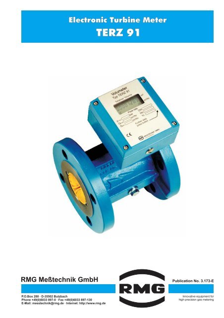
Electronic Turbine Meter<br />
<strong>TERZ</strong> <strong>91</strong><br />
RMG Meßtechnik GmbH<br />
Publication No. 3.173-E<br />
P.O.Box 280 · D-35502 Butzbach<br />
Phone +49(0)6033 897-0 · Fax +49(0)6033 897-130<br />
E-Mail: messtechnik@rmg.de · Internet: http://www.rmg.de<br />
Innovative equipment for<br />
high-precision gas metering
1. Function<br />
The electronic turbine meter <strong>TERZ</strong> <strong>91</strong> is a flow meter<br />
directly measuring the volume flow rate of gases at<br />
actual conditions. The flow rate measured and the<br />
volume are displayed on an electronic index head.<br />
The method of operation of the meter is based on<br />
velocity measurement using a turbine wheel. The gas<br />
flow passes the ring-shaped inlet section of the flow<br />
straightener and reaches the coaxially mounted<br />
turbine wheel, whose speed is proportional to the<br />
mean velocity of the gas flow within the scope of the<br />
measuring range.<br />
The speed of the turbine wheel is recorded inductively<br />
using non-contact measurement by a pulse-wire<br />
sensor and a permanent magnet. Due to the fact that<br />
the signal frequency is directly picked up at the turbine<br />
wheel, the meter is also suitable for control<br />
applications.<br />
2.<br />
Construction<br />
The electronic turbine meters form a series of uniform<br />
construction. Each meter consists of four structural<br />
units (see drawing). An aerodynamic flow straightener<br />
fitted into the meter case constricts the effective cross<br />
section of the pipe to form a ring-shaped crosssectional<br />
area and substantially eliminates<br />
turbulences. This increases the velocity of the flowing<br />
gas. The shaft mounted with ball-bearings carries the<br />
turbine wheel on the one side and a permanent<br />
magnet rotating before the sensor on the other. The<br />
duct of the sensor sleeve towards the unpressurized<br />
section of the index head is sealed off by a pressuretight<br />
O-ring. By means of the setscrew the index head<br />
can be fixed in the most favourable position for taking<br />
readings.<br />
Index head<br />
O-ring<br />
Sensor sleeve<br />
Setscrew<br />
O-ring<br />
Sensor<br />
Flow straightener<br />
Permanent magnet<br />
Turbine wheel<br />
Ball bearing<br />
3. Types of gases<br />
The <strong>TERZ</strong> <strong>91</strong> standard design is suitable for all gases<br />
complying with the DVGW working sheet G260. The<br />
materials used are appropriate for gases and fuel<br />
gases, such as natural gas, refinery gas, liquid gases<br />
and their mixtures, nitrogen, CO (dry), air and all<br />
2<br />
inert gases.<br />
For aggressive and chemical gases, there are special<br />
designs available with PTFE lining, special material,<br />
special lubrication, etc.
max<br />
max<br />
min<br />
4. Characteristics<br />
<br />
<br />
<br />
<br />
<br />
<br />
For secondary metering<br />
Electronic totalizers<br />
(Main totalizer, additionally start/stop or resettable<br />
totalizer)<br />
Battery mode (with Type <strong>TERZ</strong> <strong>91</strong>)<br />
Service life of the battery is a minimum of 6 years<br />
4-20 mA current output<br />
(with Type <strong>TERZ</strong> <strong>91</strong>-S)<br />
Low-torque metering system with long-term<br />
stability<br />
(apart from the turbine wheel, there are no<br />
mechanically actuated parts)<br />
LF and HF pulse outputs<br />
(The pulse value of the LF pulse output can be<br />
adjusted)<br />
<br />
<br />
<br />
<br />
<br />
<br />
Intrinsically safe circuit, approved for zone 1<br />
Degree of protection: IP 65<br />
Flow display<br />
Option for external disablement of the counting<br />
mechanism<br />
(in order to suppress overtravel)<br />
Compact construction with a rotatable counter<br />
head<br />
Option for use as a remote counting mechanism<br />
5. Approvals<br />
EEx ib II C T4<br />
as per certificate of conformity No.: Ex 96.D.2041<br />
DVGW product ident No. CE-0085BN0292<br />
6. Electronic index head<br />
Possible connections of the electronic index head:<br />
HF pulse output<br />
(high frequency)<br />
direct signal frequency<br />
Transistor, open collector<br />
as per NAMUR specification<br />
U = 13.5 V (Ex)<br />
30 V (non Ex)<br />
LF pulse output<br />
(low frequency)<br />
decade-scaled<br />
Transistor, open collector<br />
as per NAMUR specification<br />
Switch input<br />
for stopping the totalizer<br />
voltage-controlled<br />
(optocoupler)<br />
4-20 mA current output<br />
Type <strong>TERZ</strong> <strong>91</strong>-S<br />
(option)<br />
max U max = 13.5 V (Ex)<br />
Totalizer stop:<br />
U max = 30 V<br />
30 V (non Ex) 5V
7 . Overview<br />
Nominal size Measuring range Pulse value Pressure loss Lubrication<br />
Q min -Q max<br />
LF 1) HF 2) p<br />
mm in. m 3/h<br />
pulses/m 3 pulses/m 3 mbar permanently<br />
lubricated<br />
oil pump<br />
25<br />
40<br />
50<br />
1<br />
1½<br />
2<br />
2.5 -<br />
5-<br />
6-<br />
25<br />
70<br />
100<br />
10/100<br />
1/10/100<br />
1/10/100<br />
13450<br />
7800<br />
7800<br />
3<br />
4<br />
5<br />
•<br />
•<br />
•<br />
80<br />
100<br />
150<br />
200<br />
250<br />
300<br />
400<br />
500<br />
600<br />
3<br />
4<br />
6<br />
8<br />
10<br />
12<br />
16<br />
20<br />
24<br />
10 -<br />
25 -<br />
40 -<br />
100 -<br />
160 -<br />
250 -<br />
400 -<br />
650 -<br />
1000 -<br />
250<br />
400<br />
1000<br />
1600<br />
2500<br />
4000<br />
6500<br />
10000<br />
16000<br />
0.1/ 1/10<br />
0.1/ 1/10<br />
0.1/ 1/10<br />
0.1/ 1<br />
0.1/ 1<br />
0.1/ 1<br />
0.1/1<br />
0.1/1<br />
0.01/ 0.1<br />
2375<br />
1060<br />
330<br />
135<br />
75<br />
48<br />
24<br />
12<br />
6<br />
6<br />
4<br />
6<br />
3<br />
3<br />
4<br />
3<br />
4<br />
4<br />
•<br />
•<br />
•<br />
•<br />
•<br />
•<br />
•<br />
•<br />
•<br />
3<br />
4<br />
6<br />
8<br />
10<br />
12<br />
16<br />
20<br />
24<br />
25 -<br />
40 -<br />
100 -<br />
160 -<br />
250 -<br />
400 -<br />
650 -<br />
1000 -<br />
1600 -<br />
400<br />
650<br />
1600<br />
2500<br />
4000<br />
6500<br />
10000<br />
16000<br />
25000<br />
0.1/ 1<br />
0.1/ 1/10<br />
0.1/ 1<br />
0.1/ 1<br />
0.1/ 1<br />
0.1/ 1<br />
0.1/1<br />
0.01/ 0.1<br />
0.01/ 0.1<br />
1250<br />
600<br />
190<br />
80<br />
44<br />
28<br />
14<br />
7<br />
4<br />
14<br />
10<br />
12<br />
8<br />
7<br />
9<br />
8<br />
9<br />
9<br />
•<br />
•<br />
•<br />
•<br />
•<br />
•<br />
•<br />
•<br />
•<br />
1) Standard values (set in the factory) are shown in bold type<br />
2) Approximate value; the exact value is determined during calibration<br />
8. Pressure loss<br />
The pressure loss p stated in the table applies to natural<br />
gas at Qmax<br />
and under 1 bar. From this, the pressure loss<br />
at actual conditions can be calculated in accordance with<br />
the formula below.<br />
Pressure loss as per the formula<br />
2<br />
<br />
p = p n Q<br />
a • • p a<br />
a •<br />
0.81 ( Qmax )<br />
p<br />
a = Pressure loss at actual conditions (p a, Q a) in<br />
mbar<br />
p = Pressure loss at Qmax<br />
and natural gas at 1 bar<br />
in mbar (see table)<br />
n<br />
= Standard density of the process gas (kg/m 3)<br />
p a = Pressure at actual conditions in bar (absolute)<br />
Q a = Flow rate at actual conditions (m 3/h)<br />
Q = Maximum flow rate<br />
max<br />
Example: Air, nominal meter size DN 100, measuring<br />
range 20 - 400 m 3/h,<br />
p a = 1.1 bar(abs),<br />
n<br />
= 1.29 kg/m 3, Q a = 250 m 3/h<br />
take from the table: p = 4 mbar<br />
Hence:<br />
1.29 250<br />
p a = 4 • • 1.1 • = 2.74 mbar<br />
0.81 400<br />
9. Measuring accuracy<br />
Measuring error: ± 2% for Qmin to 0.2 · Qmax<br />
± 1% for 0.2 · Qmax<br />
to Qmax<br />
(DN 25: ± 2% for Qmin<br />
to Q max)<br />
Reproducibility: ± 0.5%<br />
10. Maintenance<br />
( )<br />
All turbine meters up to and including the nominal size of<br />
DN 150 are fitted with permanently lubricated bearings<br />
and require no maintenance. From the nominal size of<br />
DN 200, the meters are fitted with a lubricator.<br />
Lubrication is to be performed in compliance with the<br />
operating instructions (see also lubrication instruction<br />
plate at the meter).<br />
2
11. Types of construction and dimensions<br />
A<br />
A<br />
A<br />
A<br />
B<br />
C<br />
B<br />
C<br />
B<br />
C<br />
B<br />
C<br />
L<br />
L<br />
L<br />
L<br />
Flanged-end Design ( F)<br />
Sandwich design ( S)<br />
Monoflange design ( M)<br />
Threaded-end design ( G)<br />
(Adaptor-flange mounting)<br />
(only aluminium cases)<br />
Weights and measures<br />
Pressure stages<br />
Case Nominal L A B C Weight PN 10 PN 25 PN 40 ANSI 300 PN 64<br />
design size mm mm mm mm kg PN 16 ANSI 150 PN 100<br />
mm ANSI 600<br />
G<br />
25<br />
1)<br />
185 80 145 195 4 Alu<br />
Threads 40 2) 140 80 145 195 4 Alu<br />
50 150 60 180 265 10 • • • •<br />
80 120 35 215 315 14 • • •<br />
100 150 50 225 345 25 • • •<br />
150 175 70 255 410 40 • • •<br />
200 200 70 280 470 60 • • •<br />
F<br />
250 300 135 320 540 70 • •<br />
300 95 325 580 100 • •<br />
300<br />
450 200 325 610 200<br />
• • •<br />
Flanges 400 145 335 650 180 • •<br />
400<br />
600 345 335 680 400<br />
• • •<br />
500<br />
400 110 385 760 300 • •<br />
750 260 385 810 650<br />
• • •<br />
600<br />
600 130 440 870 400 • •<br />
900 280 440 920 850<br />
•<br />
50 80 60 175 255 15<br />
•<br />
80 120 35 200 300 35<br />
• •<br />
M 100 150 50 225 355 50<br />
• •<br />
Mono- 150 175 70 270 445 100<br />
• •<br />
flanges 200 200 70 305 510 130<br />
• •<br />
250 250 85 345 590 200<br />
• • •<br />
50 80 30 145 195 123)<br />
Alu •<br />
80 120 30 200 280 20 • •<br />
100 150 50 220 330 30 • •<br />
S<br />
150 175 70 250 400 50 • •<br />
Sandwich 200 200 70 280 450 70 • •<br />
250 250 85 315 530 110 • •<br />
1) External thread R 1½"; with coupling kit: internal thread Rp1 ISO 7-1, overall length 243 mm<br />
2) External thread R 2¼"; with coupling kit: internal thread Rp1½ ISO 7-1, overall length 206 mm<br />
3) 4 kg for PN 10 and PN 16 (aluminium case)<br />
Special designs on request
max<br />
max<br />
min<br />
Weitere Daten:<br />
Schalter drücken<br />
MESSTECHNIK GMBH<br />
35510 Butzbach<br />
Electronic Turbine Meter<br />
<strong>TERZ</strong> <strong>91</strong><br />
12. Options for mounting the index head<br />
By mounting the electronic index head in different ways,<br />
optimum readings can be taken in any position. If no<br />
special type of installation is specified, the index head is<br />
to be installed in accordance with the figure below.<br />
00064419<br />
F 1.4<br />
Standard design<br />
Electronic Turbine Meter<br />
Type <strong>TERZ</strong> <strong>91</strong><br />
Volume<br />
00064419 m³<br />
F 1.4 m³/h Index head<br />
Flow rate<br />
p<br />
bar DN<br />
Q<br />
m³/h No.<br />
Q<br />
m³/h Yr.<br />
LIYCY cable<br />
2x0.75 blue<br />
00064419<br />
F 1.4<br />
00064419<br />
F 1.4<br />
max. cable length: 50 m<br />
Options for mounting the index head<br />
Remote index<br />
Measuring<br />
element<br />
13. Mounting and operating instructions<br />
<strong>TERZ</strong> <strong>91</strong> turbine meters can be operated in any position<br />
up to the nominal size of DN 200. From the nominal size<br />
of DN 250, they can only be installed in a horizontal<br />
position. By loosening the setscrew, the index head can<br />
be rotated by 360° to achieve an optimum position for<br />
taking readings. In the event of difficult mounting<br />
conditions, the counter head can also be installed<br />
separately as a remote index. It is also possible to retrofit<br />
the <strong>TERZ</strong> <strong>91</strong> turbine meter as a remote index.<br />
Special instructions for start-up and operation:<br />
Caution!<br />
Turbine meters are precise measuring instruments<br />
and must be carefully handled during transport,<br />
storage and operation.<br />
Do not fill any downstream pipelines or station<br />
sections via the turbine meter. This may result in<br />
excesive flow rates with resultant damage to the<br />
turbine wheel.<br />
The meter has been designed for short-time overload<br />
operation at up to 1.2 times the value of Q max. However,<br />
such load conditions should be avoided in order to<br />
protect the <strong>TERZ</strong> <strong>91</strong> from any unnecessary high load.<br />
The gas flow must be free of shocks and pulsations as<br />
well as free of foreign particles, dust and liquids.<br />
Otherwise it is recommended that filters and separators<br />
be installed.<br />
Avoid any components fitted directly upstream of the<br />
turbine meter which would affect the gas flow (see<br />
DVGW guidelines and PTB guideline G 13).<br />
The meter must be installed in weather-proof locations.<br />
For outside installations, appropriate guards must be<br />
provided against direct weathering influences. The<br />
<strong>TERZ</strong> <strong>91</strong> can be used at following temperatures:<br />
Temperature range of fluids: -20°<br />
C bis +60°C<br />
Ambient temperature range: -20°C bis +50°C<br />
Special designs for higher and lower temperatures are<br />
available.<br />
RMG Meßtechnik GmbH<br />
Publication No. 3.173-E<br />
P.O.Box 280 · D-35502 Butzbach<br />
Telefon +49 (0)6033 897-0 · Fax +49 (0)6033 897-130<br />
E-Mail: messtechnik@rmg.de · Internet: http://www.rmg.de<br />
Status 04/2003<br />
Subject to technical change