Thermodynamics and Transport Model of Charge ... - IEEE Xplore
Thermodynamics and Transport Model of Charge ... - IEEE Xplore
Thermodynamics and Transport Model of Charge ... - IEEE Xplore

Create successful ePaper yourself
Turn your PDF publications into a flip-book with our unique Google optimized e-Paper software.
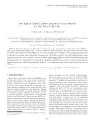
2728 <strong>IEEE</strong> TRANSACTIONS ON ELECTRON DEVICES, VOL. 55, NO. 10, OCTOBER 2008<br />
<strong>Thermodynamics</strong> <strong>and</strong> <strong>Transport</strong> <strong>Model</strong> <strong>of</strong> <strong>Charge</strong><br />
Injection in Silicon Irradiated by a<br />
Pulsed Focused Laser<br />
Étienne Boulais, Vincent Binet, Jean-Yves Degorce, Guillaume Wild,<br />
Yvon Savaria, Fellow, <strong>IEEE</strong>, <strong>and</strong> Michel Meunier<br />
Abstract—Focused pulsed visible laser used in laser-trimming<br />
technologies such as the laser diffused-resistor process may inject<br />
charges in the semiconductor, leading to an interaction with highly<br />
sensitive circuits. In order to evaluate the process impact on those<br />
circuits, a study <strong>of</strong> the perturbation on the free-running frequency<br />
<strong>of</strong> a ring oscillator due to a nearby laser pulse has been made. The<br />
behavior <strong>of</strong> this modification as a function <strong>of</strong> the laser-pulse power<br />
exhibits complex features. A thermodynamics <strong>and</strong> electrical model<br />
<strong>of</strong> the charge injection by a focused pulsed laser on silicon has been<br />
developed. First, the laser-induced charge diffusion is calculated<br />
by a finite-element-model coupling Boltzmann semiclassical transport<br />
<strong>and</strong> thermodynamic equations; the last one being necessary,<br />
as relatively high laser power may increase significantly the local<br />
temperature. The result is then fed into an electrical model <strong>of</strong><br />
the ring oscillator as a perturbation injected by a current source.<br />
This model coupled to parasitic-light effects due to geometrical<br />
changes during silicon melting is able to explain the oscillator’s<br />
operation-frequency modification.<br />
Index Terms—<strong>Charge</strong> injection, finite-element model, laser<br />
trimming, substrate effect, temperature effect.<br />
I. INTRODUCTION<br />
CLASSES <strong>of</strong> analog microelectronic circuits require highprecision<br />
resistors to function properly. St<strong>and</strong>ard integrated<br />
fabrication processes’ intrinsic variability can introduce<br />
some uncontrolled changes in parametric values that can<br />
severely limit their accuracy, possibly resulting in a completely<br />
useless circuit. A solution to this problem consists in a postproduction<br />
trimming <strong>of</strong> resistor values to obtain the desired<br />
electrical characteristics. The possibility to configure circuits<br />
by creating or cutting metal links [1] allows designers to add re-<br />
Manuscript received October 5, 2007; revised June 27, 2008. Current version<br />
published September 24, 2008. This work was supported in part by the Natural<br />
Sciences <strong>and</strong> Engineering Council <strong>of</strong> Canada <strong>and</strong> in part by LTRIM. The review<br />
<strong>of</strong> this paper was arranged by Editor C.-Y. Lu.<br />
É. Boulais <strong>and</strong> M. Meunier are with the Laser Processing Laboratory,<br />
Engineering Physics Department, École Polytechnique de Montréal,<br />
Montreal, QC H3C 3A7, Canada (e-mail: etienne.boulais@polymtl.ca; michel.<br />
meunier@polymtl.ca).<br />
V. Binet, G. Wild, <strong>and</strong> Y. Savaria are with the Groupe de Recherche en<br />
Microélectronique, Electrical Engineering Department, École Polytechnique de<br />
Montréal, Montreal, QC H3C 3A7, Canada (e-mail: vincent.binet@polymtl.ca;<br />
guillaume.wild@polymtl.ca; yvon.savaria@polymtl.ca).<br />
J.-Y. Degorce was with the Laser Processing Laboratory, Engineering<br />
Physics Department, École Polytechnique de Montréal, Montreal, QC H3C<br />
3A7, Canada. He is now with the Université de Bordeaux, 33000 Bordeaux,<br />
France (e-mail: Degorce.JeanYes@celia.u-bordeaux1.fr).<br />
Digital Object Identifier 10.1109/TED.2008.2003027<br />
dundancy <strong>and</strong> correct malfunction in large VLSI circuits. Thinfilm<br />
resistors can also be trimmed by laser to improve accuracy<br />
<strong>of</strong> digital-to-analog converters [2], analog-to-digital converters<br />
[3], <strong>and</strong> read-only memories [4]. An alternative simple, costeffective,<br />
<strong>and</strong> rapid laser trimming process was recently proposed<br />
by Meunier et al. [5] <strong>and</strong> consists in the formation <strong>of</strong><br />
diffused resistors that can be used directly in mixed signal <strong>and</strong><br />
high-precision analog circuits [6]. This process uses a pulsed<br />
visible laser focused on a semiconductor structure consisting<br />
<strong>of</strong> two highly doped regions separated by a gap. The laser<br />
induces a local melting <strong>of</strong> the silicon surface, thus stimulating<br />
the diffusion <strong>of</strong> dopants <strong>and</strong> the formation <strong>of</strong> an analog resistive<br />
device, whose resistance can be accurately controlled by an<br />
iterative technique [7].<br />
Electron–hole pairs that might be created by the laser during<br />
these processes <strong>and</strong> injected into the substrate must remain<br />
below an acceptable level for industrial applications, as they<br />
can possibly activate destructive phenomena such as latch up<br />
<strong>and</strong> corrupt accuracy in closed-loop trimming methods that<br />
rely on accurate analog measurements. There is thus a need<br />
to develop a tool that will enable us to accurately calculate<br />
the charge injection in an integrated circuit during a trimming<br />
process. Preceding works on laser interaction with electronic<br />
circuit has been made within the fields <strong>of</strong> fault-injection <strong>and</strong><br />
single-event effects [8], [9]. However, as research in those fields<br />
involves very low power laser beam focused on transistors, laser<br />
trimming is usually processed at much higher power pulses (by<br />
three to four orders <strong>of</strong> magnitude), leading to a local temperature<br />
increase <strong>and</strong> to different charge-injection mechanisms <strong>and</strong><br />
impacts on surrounding circuits. Therefore, models developed<br />
for fault-injection <strong>and</strong> single-event effects cannot be used, since<br />
thermodynamic effects on charge transport induced by laser<br />
heating are ignored. Previous work by Wild et al. [10] has<br />
shown that a ring oscillator can be used to detect very small<br />
laser-induced charge injection into the silicon by monitoring its<br />
frequency change during the tuning process. The purpose <strong>of</strong> this<br />
paper is to model both the charge injection in silicon due to a<br />
focused visible laser beam <strong>and</strong> the effect <strong>of</strong> charge injection<br />
on an operating ring oscillator. A finite-element model using<br />
coupled thermodynamic <strong>and</strong> semiclassical charge-transport<br />
equations is used for the charge-injection calculation, while an<br />
electrical model <strong>of</strong> the ring oscillator, including substrate <strong>and</strong><br />
well extraction, is used to calculate the impact <strong>of</strong> the charge<br />
injection on the circuit.<br />
0018-9383/$25.00 © 2008 <strong>IEEE</strong>
BOULAIS et al.: THERMODYNAMICS AND TRANSPORT MODEL OF CHARGE INJECTION IN SILICON 2729<br />
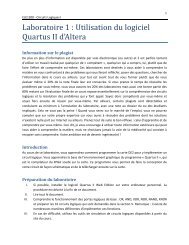
Fig. 1. (a) Schematic <strong>of</strong> a ring oscillator composed <strong>of</strong> four inverters <strong>and</strong> an AND gate. All inverters are equidistant to the target. (b) Typical result <strong>of</strong> the FVC<br />
output after a 950-mW 100-ns pulsed laser irradiating the center <strong>of</strong> the ring oscillator situated at 30 μm.<br />
II. EXPERIMENTAL SETUP AND RESULTS<br />
As described in [10], the sensitive circuits used to detect<br />
injected charges in the experimental work are CMOS ring<br />
oscillators, manufactured by TSMC in a 0.18-μm technology<br />
that has a low-resistivity p-type substrate. Oscillating at a<br />
stable frequency, the ring oscillator, as previously presented by<br />
Wild [10], is composed <strong>of</strong> four inverters <strong>and</strong> a gating NAND acting<br />
as an inverter during the oscillation operation. A frequencyto-voltage<br />
converter (FVC) is used to drive the chip output at<br />
a voltage that represents the oscillator’s frequency, as shown<br />
in Fig. 1. The on-chip oscillation <strong>of</strong> about 380 MHz is first<br />
divided by eight using a frequency divider (FD), then each<br />
period is converted by the FVC to a dc voltage that drives the<br />
output <strong>of</strong> the chip through an analog buffer. The laser target<br />
is a laser diffused resistor (LDR) implanted in the center <strong>of</strong><br />
the ring oscillator <strong>and</strong> located at various distance d to the<br />
ring oscillator, ranging from 20 to 40 μm. A test setup has<br />
been developed as described in [10] using a frequency-doubled<br />
continuous-wave Nd:YAG laser (532 nm) having an adjustable<br />
diameter <strong>and</strong> power. A pulse is selected from the continuous<br />
beam using an acoustooptic modulator <strong>and</strong> is focalized on<br />
the target. In all experiments, a single pulse is used with a<br />
pulse duration <strong>of</strong> 100 ns. The beam diameter is about 7 μm,<br />
<strong>and</strong> the emitted laser power P L is varying up to 1.5 W. Note<br />
that, throughout the text, the emitted laser power refers to<br />
the average laser power <strong>of</strong> the continuous-wave laser, taking<br />
into consideration losses due to the acoustooptic modulator.<br />
It is difficult to evaluate the optical losses due to the multiple<br />
reflections <strong>and</strong> the absorption in the interdielectric layers;<br />
the exact laser power arriving on the silicon is not known.<br />
A typical FVC variation for P L = 950 mW <strong>and</strong> d = 30 μm<br />
is given in Fig. 1(b). The measured maximum <strong>of</strong> the FVC<br />
output variation [FVCOV max defined in Fig. 1(b)] is shown in<br />
Fig. 2 as a function <strong>of</strong> the laser power P L . Estimations based<br />
on diffused-resistor creation experiments <strong>and</strong> in situ reflectivity<br />
measurements give a value for the melting power threshold <strong>of</strong><br />
around P L,th−m =(1.1 ± 0.1) W. One can distinguish three<br />
main regions in these measured results: 1) In the first region,<br />
for P L < 0.375 W, the FVC output increases with P L ;2)in<br />
the second region (0.375 W 0.7 W), the FVC output increases slightly with scattered<br />
results. An increase in charge injection with increasing power<br />
was expected. The presence <strong>of</strong> region II was not expected.<br />
To explain these results, the effects <strong>of</strong> heating on the charge<br />
transport must considered.<br />
III. CONSTANT-TEMPERATURE ELECTRONIC<br />
TRANSPORT MODEL<br />
Many models describing the interaction between a laser pulse<br />
<strong>and</strong> a semiconductor developed over the past four decades focus<br />
on emulating the impact <strong>of</strong> single-event effects by ionizing<br />
radiation on static memories [9], [11], [12]. In these existing<br />
models, relatively low laser powers are assumed, as any heating<br />
phenomena are excluded from the calculation. However, the<br />
laser used for creating LDRs is different in terms <strong>of</strong> power<br />
level <strong>and</strong> pulse duration, since significant heating <strong>and</strong> melting<br />
<strong>of</strong> silicon is required. As a first approximation, the substrate’s<br />
temperature was assumed to remain constant throughout the<br />
process. It will be shown that this assumption is not accurate.<br />
It is important to note that the laser is not directly focused<br />
on the active area <strong>of</strong> a transistor under test, but rather on the<br />
LDR region, which introduces additional specificity into the
2730 <strong>IEEE</strong> TRANSACTIONS ON ELECTRON DEVICES, VOL. 55, NO. 10, OCTOBER 2008<br />
model. Electron–hole pairs are thus not directly generated on<br />
the transistor drain but can rather reach the circuit under test,<br />
which is a ring oscillator, through a drift <strong>and</strong> diffusion process<br />
that will be described by a finite-element model based on<br />
Boltzmann semiclassical transport equations. An electric model<br />
must also be used to characterize the effects <strong>of</strong> the injected<br />
charges on the circuit under test.<br />
A. Electrical <strong>Model</strong><br />
In order to get an accurate model <strong>of</strong> the victim circuit, the<br />
complete circuit has to be extracted from a detailed layout.<br />
As the coupling between the laser-pulse impact <strong>and</strong> the victim<br />
circuit takes place through the substrate, the model must also<br />
include a thorough substrate extraction. As significant currents<br />
flow into the substrate, the potentials around active devices are<br />
significantly perturbed, which modulates the electrical parameters<br />
<strong>of</strong> the victim circuit through body effects. To include<br />
substrate coupling in the model, commercial s<strong>of</strong>twares like<br />
SubstrateStorm, Substrate Coupling Analysis (SCA), or Assura<br />
RCX (Cadence S<strong>of</strong>tware) could be used to extract substrate<br />
parasitic components <strong>and</strong>, thus, build a resistive <strong>and</strong> capacitive<br />
substrate model. However, existing literature [13] on substrate<br />
modeling <strong>and</strong> parasitic extraction is mostly focused on noise<br />
coupling injected by a large number <strong>of</strong> switching gates. In [14],<br />
such models based only on capacitive coupling have shown<br />
inaccuracy when potentials vary over a wide range. These<br />
models become particularly inaccurate when the potentials shift<br />
by more than 400 mV <strong>and</strong> some normally inactive devices get<br />
activated. Mixed-mode simulations have shown that such large<br />
variations effectively occur in our case. In order to correctly<br />
model the charge-injection phenomena, a custom model <strong>of</strong><br />
the substrate has been developed by enriching capacitive- <strong>and</strong><br />
resistive-only substrate models given by the Cadence SCA<br />
tool. This custom substrate model includes vertical bipolar<br />
transistors <strong>and</strong> diodes to represent well–substrate junctions.<br />
They are added as discrete elements whose models are based on<br />
those provided by TSMC, <strong>and</strong> their size parameters are adjusted<br />
according to the physical layout <strong>of</strong> the circuit.<br />
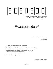
<strong>Charge</strong> injection is then modeled by sources injecting currents<br />
through different junctions present in the ring-oscillator<br />
test circuit. As shown in Fig. 3, different perturbation sites have<br />
been identified to model the charge–circuit interaction in each<br />
<strong>of</strong> the inverters comprised in the circuit. Current source (A)<br />
simulates most <strong>of</strong> the charges collected by the n-well–substrate<br />
junction, whereas sources (B) <strong>and</strong> (C) connected between the<br />
source/drain nodes <strong>of</strong> the transistor <strong>and</strong> the bulk node represent<br />
charges collected by the NMOS. The last two sources (D)<br />
<strong>and</strong> (E) model injection into PMOSs’ drains <strong>and</strong> sources.<br />
All these sources correspond to possible physical-interaction<br />
mechanisms between charges present in the substrate <strong>and</strong> the<br />
circuit. Performing a series <strong>of</strong> circuit simulations, it was found<br />
that sources B, C, D, <strong>and</strong> E have relatively minor effects<br />
on the oscillator behavior <strong>and</strong> can be neglected. This can be<br />
understood because the surface <strong>of</strong> the well associated to source<br />
A is much larger (by a factor over ten) than the surface <strong>of</strong> the<br />
physical structures associated to the other sources. Using the<br />
detailed circuit models, including all available circuit, layout,<br />
substrate, <strong>and</strong> parasitic-device information, the complete ringoscillator<br />
model is then built <strong>and</strong> connected to the rest <strong>of</strong> the<br />
chip model, including the FVC, package, <strong>and</strong> bonding wires. In<br />
the first approximation, it was assumed that the FVC <strong>and</strong> other<br />
secondary circuits that are much further away from the laserpulse<br />
impact point remain unaffected by laser-induced charges.<br />
B. Constant-Temperature Semiconductor <strong>Transport</strong> <strong>Model</strong><br />
In a first approximation, by neglecting temperature rise <strong>of</strong> the<br />
substrate, it is possible to model the charge-injection process in<br />
silicon by simply coupling a Beer–Lambert equation for light<br />
absorption with Poisson <strong>and</strong> Boltzmann equations describing<br />
the charge drift <strong>and</strong> diffusion processes. Dopants are assumed to<br />
be completely ionized within the considered temperature range.<br />
Continuity equation relating the electrons concentration n <strong>and</strong><br />
the current density J n is thus given by<br />
∂n<br />
∂t = 1 −→ ∇·−→<br />
Jn + G n − r n . (1)<br />
e<br />
A similar equation for holes has been used. Recombination<br />
term r n in (1) includes Shockley–Read–Hall (SRH) <strong>and</strong><br />
Auger recombination. Appropriate coefficients for silicon can<br />
be found in [15]. A dynamic SRH recombination process can<br />
be used [16], but simulations showed that results were very<br />
close to those obtained by using a st<strong>and</strong>ard equilibrium SRH<br />
expression. Optical generation term G optical is calculated by<br />
assuming that every absorbed photon <strong>of</strong> energy hν causes an<br />
interb<strong>and</strong> transition, thus creating a hole–electron pair<br />
α(T )I<br />
G optical = (2)<br />
hν<br />
where α is the temperature-dependent bulk-absorption coefficient<br />
<strong>and</strong> I in joules per square centimeter is the laser intensity<br />
arriving on the silicon. Intrab<strong>and</strong> absorption is ignored,<br />
since simulations showed that, for laser powers used here, the<br />
maximum carrier density is not enough to stimulate such contribution.<br />
Current density is calculated through the Boltzmann<br />
kinetic equation [17]<br />
( )<br />
−→ −→ F J n = neμ n E + nμn T ∇<br />
T<br />
G n 5/2<br />
+ nμ n k B<br />
G n ∇T (3)<br />
3/2<br />
where μ n is the electron mobility, −→ E is the electric vector field,<br />
F is the quasi-Fermi level, <strong>and</strong> G m is defined as<br />
with<br />
G m =<br />
∫ ∞<br />
0<br />
τx m e x−η dx<br />
(1 + e x−η ) 2 (4)<br />
η = F n − ε gap<br />
. (5)<br />
k B T<br />
Note that all these parameters are position ( −→ r )-dependent.<br />
Similar equations for p can be obtained where the laser term in<br />
(3) changes sign, <strong>and</strong> η p = −F p /k B T .
BOULAIS et al.: THERMODYNAMICS AND TRANSPORT MODEL OF CHARGE INJECTION IN SILICON 2731<br />
Fig. 3.<br />
Custom electrical model <strong>of</strong> an inverter <strong>of</strong> the ring oscillator.<br />
The exact position-dependent mobility parameters for both<br />
holes <strong>and</strong> electron are difficult to determine, since integrated<br />
circuits are not only composed <strong>of</strong> pure <strong>and</strong> crystalline silicon<br />
but also <strong>of</strong> polycrystalline silicon which has suffered many<br />
stresses in some regions, including high-power laser impacts<br />
<strong>and</strong> phase changes. Furthermore, the real doping-concentration<br />
pr<strong>of</strong>ile remains unknown, since those parameters are not provided<br />
by the foundry. Position-dependent dislocations, defects,<br />
<strong>and</strong> dopants would all decrease the carrier mobility, resulting<br />
in a modified position <strong>and</strong> temperature-dependent mobility<br />
given by<br />
with<br />
μ M n,p(x, y, T )=φ(x, y, T )μ C n,p(x, y, T ) (6)<br />
φ(x, y, T ) ∈ [0, 1] (7)<br />
where the superscript M <strong>and</strong> C st<strong>and</strong>s, respectively, for “modified”<br />
<strong>and</strong> “crystalline,” as the subscripts n <strong>and</strong> p, respectively,<br />
st<strong>and</strong>s for electrons <strong>and</strong> holes. Carrier mobility in crystalline<br />
silicon can be found in st<strong>and</strong>ard texts [18]. Now, since the<br />
exact expression for ϕ(x, y, t) is very difficult to obtain, both<br />
theoretically <strong>and</strong> experimentally, we propose to use in a first<br />
approximation an equivalent mobility given by<br />
with<br />
μ eq<br />
n,p(x, y, T )=φμ C n,p(x, y, T ) (8)<br />
φ ∈ [0, 1] (9)<br />
where μ eq<br />
n,p is the equivalent mobility <strong>of</strong> electrons <strong>and</strong> holes <strong>and</strong><br />
φ is an empirical parameter adjusted to fit experimental value.<br />
Similarly, the carrier recombination time is also expected to<br />
be different from the one for crystalline silicon, <strong>and</strong> a uniform<br />
equivalent recombination has been assumed<br />
τ eq<br />
n,p(x, y, t) =τ. (10)<br />
While the introduction <strong>of</strong> equivalent recombination times,<br />
absorption coefficient, <strong>and</strong> mobilities are required to fit experimental<br />
data, their influence over the general behavior <strong>of</strong><br />
Fig. 4. FVC variation as a function <strong>of</strong> laser power, (circles) experiments, <strong>and</strong><br />
(crosses) simulation.<br />
injected current as a function <strong>of</strong> incident laser power remains<br />
limited. Finite-element simulations were performed on a<br />
1.8-V reversed-biased p-n junction located at d = 30 μm from<br />
a pulsed focused laser. The calculated current was then inserted<br />
as a current source perturbing the electrical model to obtain the<br />
simulated variation <strong>of</strong> the FVC output voltage. Mobility factor<br />
<strong>and</strong> recombination time were then adjusted to fit experimental<br />
results. Simulations show that φ = 0.17 <strong>and</strong> τ = 200 ns reproduces<br />
the experimental results with the best accuracy. Fig. 4<br />
shows both the best-fit simulated <strong>and</strong> measured results <strong>of</strong> the<br />
FVC output variation as a function <strong>of</strong> P L . Results in Fig. 4<br />
show that, while the model predictions agree quite well with<br />
simulation results within the first region (P L < 0.375 W), it<br />
does not follow the behavior observed in the second region<br />
(0.375 W
2732 <strong>IEEE</strong> TRANSACTIONS ON ELECTRON DEVICES, VOL. 55, NO. 10, OCTOBER 2008<br />
IV. COUPLED THERMODYNAMICS AND<br />
TRANSPORT MODEL<br />
A. Coupled Thermodynamic <strong>and</strong> <strong>Transport</strong> <strong>Model</strong><br />
Without Fusion<br />
In this improved model based on coupled thermodynamic<br />
<strong>and</strong> transport equations, the carrier spatial distribution is simulated<br />
in a two-step process. Temperature is first calculated<br />
using a model essentially based on the one introduced by<br />
Degorce et al. [19], involving the resolution <strong>of</strong> coupled<br />
Beer–Lambert <strong>and</strong> heat equations, where the phase transformation<br />
is accounted for by using an enthalpic model. Siliconoxide<br />
effect on temperature distribution is neglected to reduce<br />
the model’s complexity. The carrier distribution is then determined<br />
through the resolution <strong>of</strong> the coupled Boltzmann <strong>and</strong><br />
Poisson equations. The temperature calculated in the first step<br />
is used into these equations without any explicit feedback.<br />
However, carrier-distribution effects on temperature are taken<br />
into account by using an empirical relation <strong>of</strong> the temperaturedependent<br />
absorption coefficient α(T ). This approximation reduces<br />
greatly the model’s complexity. The calculated maximum<br />
temperature gradient <strong>of</strong> 3.5 × 10 7 K/cm remains small enough<br />
to justify the use <strong>of</strong> Boltzmann equation for any laser power<br />
considered in this paper. As expected, temperature gradient has<br />
a considerable effect on the charge transport in the material<br />
which can be easily understood by looking at the Boltzmann<br />
equation. Developing (3), for the electrons, one can write<br />
Fig. 5. Schematic <strong>of</strong> the time evolution <strong>of</strong> the distribution <strong>of</strong> electronic current<br />
in the material. At the beginning <strong>of</strong> the pulse (A), electrons induced in the<br />
material diffuse from the laser impact point to the circuit. The laser heats<br />
the substrate, <strong>and</strong> when temperature gradient gets high enough over a certain<br />
area (B), this area experiences an inversion <strong>of</strong> its electronic current. After the<br />
end <strong>of</strong> the pulse (C), the temperature gradient gets lower, <strong>and</strong> the inverse current<br />
area disappear.<br />
( )<br />
−→ G5/2<br />
J n = −enμ n ∇V + nμ n ∇F − k B nμ n − η ∗ ∇T<br />
G 3/2<br />
(11)<br />
where the first terms represent the drift <strong>and</strong> temperatureconstant<br />
diffusion current <strong>and</strong> the last one corresponds to<br />
a current generated when a temperature gradient is present<br />
within the material. A similar equation can be obtained for<br />
holes. Calculations show that the coefficient multiplying the<br />
temperature gradient (11) is always positive. In our application,<br />
in addition to injecting carriers, the laser acts as a heat source<br />
generating a thermal gradient having the same sign as the<br />
carrier concentration <strong>and</strong> the quasi-Fermi level. Therefore, the<br />
temperature gradient always opposes the effect <strong>of</strong> the carrierconcentration<br />
gradient, here represented by the quasi-Fermi<br />
level gradient, on the diffusion current. Strong temperature<br />
gradient could limit <strong>and</strong> even stop the diffusion <strong>of</strong> carriers from<br />
the laser impact point to the junction. Fig. 5 shows a schematic<br />
time pr<strong>of</strong>ile <strong>of</strong> the electronic current present in the material.<br />
As shown in Fig. 5, when a strong temperature gradient is<br />
present in the material, an inversion <strong>of</strong> the electronic current is<br />
experienced over a small area <strong>of</strong> the substrate. Carriers are then<br />
confined in this small region limited by this diffusion barrier<br />
where they can recombine. Only carriers created at the very<br />
beginning <strong>of</strong> the laser pulse, which is before the formation <strong>of</strong><br />
a strong temperature gradient, or created outside the diffusion<br />
barrier will eventually get to the junction. Fig. 6 shows a<br />
simulation result showing that this inversion <strong>of</strong> the electronic<br />
current indeed occurs for a 0.5-W laser pulse in a region located<br />
about 400 nm from the laser impact point. Fig. 7 now shows<br />
Fig. 6. Electronic current as a function <strong>of</strong> distance from laser impact point at<br />
the end <strong>of</strong> a 0.5-W pulse as calculated with (solid line) coupled thermodynamic<br />
<strong>and</strong> transport model <strong>and</strong> (dashed-dot line) constant-temperature semiconductor<br />
constant model.<br />
a comparison <strong>of</strong> the simulated FVC output voltage using this<br />
new model to the experimental results. Comparison <strong>of</strong> Fig. 7<br />
to Fig. 4 shows that introducing temperature effects into the<br />
semiconductor transport model permits one to almost reproduce<br />
the experimental behavior in the second region which could<br />
thus be attributed for a large part to the presence <strong>of</strong> strong<br />
temperature gradient within the substrate. It is <strong>of</strong> interest that<br />
the electrical model used to simulate FVC output is no longer<br />
valid beyond 0.7 W. At that point, the electric model predicts<br />
that current perturbation required to reproduce experimental<br />
values shortcuts the n-well junction. The linear-circuit model<br />
used here is then no longer a good approximation to the phenomena<br />
taking place. It is thus difficult to correlate simulated<br />
<strong>and</strong> experimental behaviors for incident powers beyond 0.7 W.
BOULAIS et al.: THERMODYNAMICS AND TRANSPORT MODEL OF CHARGE INJECTION IN SILICON 2733<br />
Fig. 7. FVC variations as a function <strong>of</strong> laser power, (circles) experiments, <strong>and</strong><br />
(triangles) simulation.<br />
The physical model presented so far predicts a saturation <strong>of</strong> the<br />
current entering the junction as a function <strong>of</strong> the laser power in<br />
the third region. In fact, at those powers, the temperature rise<br />
in silicon is strong enough to induce melting <strong>of</strong> the substrate.<br />
Although melting <strong>of</strong> the surface is included in the model,<br />
its direct effect on electronic transport has been neglected.<br />
The next section introduces a model that considers those<br />
effects.<br />
B. Coupled Thermodynamic <strong>and</strong> <strong>Transport</strong> <strong>Model</strong><br />
With Fusion<br />
Basically, the equations <strong>of</strong> coupled thermodynamic <strong>and</strong><br />
transport model presented in the previous section remains<br />
essentially the same, except that one must include the effect<br />
<strong>of</strong> the melted silicon, which has become metallic. Inverse<br />
bremsstrahlung then becomes the main light-absorption<br />
mechanism, <strong>and</strong> direct electron–hole pair creation can be<br />
neglected. However, when fusion temperature is reached,<br />
semiconductor–metal phase transformation induces confined<br />
electrons in covalent bonds to reach conduction b<strong>and</strong>s thus significantly<br />
increasing equilibrium electronic concentration [20].<br />
The density <strong>of</strong> states <strong>of</strong> silicon is greatly modified when melted,<br />
<strong>and</strong> the Fermi level position decreases by approximately 0.6 eV<br />
according to experimental studies [21]. The solid–liquid interface<br />
is assumed to be at equilibrium so that thermionic<br />
charge injection can be neglected. Electron mobility is also<br />
modified [22]. Therefore, at relatively high laser power, the<br />
process will result in a metal–semiconductor heterostructure<br />
whose interface moves with the melted front. Because <strong>of</strong> the<br />
Fermi level drop in the melted silicon, carriers in liquid silicon<br />
are trapped inside a 0.6-eV well. Therefore, even if the carrier<br />
density within the melted silicon is very high, those carriers<br />
are probably not able to diffuse, <strong>and</strong> they probably stay trapped<br />
inside the melted region. Melting <strong>of</strong> the substrate is thus believed<br />
to have a negligible impact on the current perturbation<br />
affecting the sensitive circuit. From simulation results <strong>and</strong> using<br />
Fermi statistics, one can estimate the number <strong>of</strong> carriers in the<br />
melted region that is able to pass over the potential barrier to be<br />
approximately 10 19 times lower than the photoinduced charges<br />
injected in the solid semiconductor outside the melted region.<br />
As the laser power increases, reflected light from the impact<br />
point could be scattered to relatively large distances<br />
through multiple reflections in the interdielectrics <strong>and</strong> reach<br />
the p-n junction, thus creating additional electron–hole pair<br />
in the silicon. A simple calculation can be made to approximate<br />
the magnitude <strong>of</strong> this scattered light. Neglecting backscattering<br />
from dielectric/dielectric interface since their refraction<br />
indexes are expected to be very similar, the proportion <strong>of</strong> light<br />
backscattered from the irradiated surface, to the interface top<br />
layer/air, <strong>and</strong> back to the surface is about 10% <strong>of</strong> the incident<br />
light at the laser impact point. However, since the target is not<br />
experimentally located exactly at the laser waist, it is expected<br />
that the incoming lightwave will not be perfectly plane at the<br />
surface, yielding to a reflected light over a large area. Moreover,<br />
when melted, the silicon surface experiences different transformations<br />
that increase this light scattering. First, liquid silicon’s<br />
reflection coefficient is about 1.5 times larger than the one <strong>of</strong><br />
solid silicon. In addition, besides reflection coefficient modification,<br />
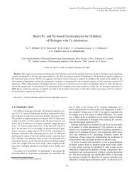
silicon undergoes purely geometrical modification when<br />
melted. Fig. 8 shows an image from a transmission electron<br />
microscopy <strong>of</strong> a silicon area which has been melted by a laser<br />
irradiation whose parameters are analog to the one used for<br />
trimming processes. Silicon has experienced strong geometrical<br />
modification <strong>and</strong> has reshaped as a rounded pyramid, similar<br />
to a sombrero shape. Other shapes have been reported in<br />
the literature, including bowl, for silicon <strong>and</strong> other material<br />
surfaces [23], [24]. These studies showed that irradiating at<br />
low energy tends to create bowllike structures, while at higher<br />
energy, sombrero structures are mostly observed. As stated<br />
in [23], bowllike structure formation results from temperature<br />
gradient inducing thermocapillarity flow that drives material<br />
from the hot center to the cold periphery. However, at higher<br />
laser power, native oxide layer is removed (at least partially),<br />
thus creating a surfactant-concentration gradient driving material<br />
toward the center. The observed sombrerolike structure is<br />
expected to increase the quantity <strong>of</strong> scattered light reaching the<br />
transistor region. Wave front at the surface is indeed no longer<br />
plane, <strong>and</strong> reflections will occur at angles far from normal, thus<br />
increasing the proportion <strong>of</strong> light reaching regions distant from<br />
the laser impact point. Scattered light creates photo-induced<br />
carriers in regions far from impact point <strong>and</strong> outside the strong<br />
temperature gradient area. Those carriers then diffuse freely<br />
to the circuit area, thus contributing to the total current. Note<br />
that all samples contained those substrate deformation from<br />
the beginning, since measurements have been conducted on a<br />
previously irradiated circuit. Consequently, the laser power at<br />
the edge <strong>of</strong> region 3 in Fig. 2 does not st<strong>and</strong> for the point at<br />
which the deformation appears but rather for the point at which<br />
scattered-light induced carrier effect on the oscillator becomes<br />
dominant over the diffusion process. Within this model, lightscattered<br />
induced carrier generation is modeled as a uniform<br />
<strong>and</strong> constant light background proportional to the incident laser<br />
power. Light-scattered generation have thus to be added to the<br />
optical generation<br />
G = G optical + G scattering . (12)
2734 <strong>IEEE</strong> TRANSACTIONS ON ELECTRON DEVICES, VOL. 55, NO. 10, OCTOBER 2008<br />
Fig. 8. (a) TEM cross-sectional image showing geometrical changes in silicon surface induced by laser melting. (b) Schematic <strong>of</strong> the scattered-light induced<br />
carrier injection backscattered from the irradiated surface to the interface top layer—air—<strong>and</strong> back to the surface.<br />
Numerical simulations has shown that 0.5% scattered-light<br />
intensity reaching regions outside the strong temperature gradient<br />
area can generate a considerable current through the<br />
junction, thereby preventing the total perturbative current to<br />
saturate as the power is increased over 700 mW in region III.<br />
Such a scattering is reasonable considering the initial 10% light<br />
reflected from the reflection on dielectric layers. Considering<br />
the experimental evidence about the existence <strong>of</strong> sample surface<br />
deformations <strong>and</strong> the small intensity <strong>of</strong> parasitic light required<br />
to produce observable effects on current, parasitic-light photoinduced<br />
carriers are thought to play an important role on the<br />
FVC output behavior at higher power.<br />
V. CONCLUSION<br />
Laser-induced diffused-resistor fabrication processes involve<br />
pulsed visible laser interaction on chips containing highly<br />
sensitive circuitry. In order to evaluate the impact <strong>of</strong> the laser<br />
pulses on these circuits, a study <strong>of</strong> the perturbation induced<br />
on the free-running frequency <strong>of</strong> a ring oscillator has been<br />
made. The behavior <strong>of</strong> this modification as a function <strong>of</strong> the<br />
laser-pulse power exhibits a quasi-linear increase for low laser<br />
power, then a saturation <strong>and</strong> finally another increase for high<br />
laser power. An electric model <strong>of</strong> the ring oscillator <strong>and</strong> <strong>of</strong><br />
the FVC circuit has been coupled to a semiconductor model<br />
<strong>of</strong> the charge injection to describe the impact <strong>of</strong> the laser<br />
pulse on the sensitive circuit. A simple model neglecting the<br />
temperature rise <strong>of</strong> the substrate is unable to describe properly<br />
the observed experimental behavior. A model based on thermodynamics<br />
<strong>and</strong> Boltzmann semiclassical transport equations<br />
<strong>of</strong> the charge injection by a focused pulsed laser in silicon has<br />
been developed to include the temperature rise <strong>of</strong> the substrate.<br />
Results show that below silicon melting, the charge injection<br />
increases linearly at low power <strong>and</strong> then saturates due to the<br />
presence <strong>of</strong> strong temperature gradient that confines photoinduced<br />
carriers in a small region around the laser impact point,<br />
thereby preventing them to diffuse to the oscillator. Above<br />
melting, silicon experiences a semiconductor-to-metal phase<br />
transition, injecting a lot <strong>of</strong> free carriers in the liquid silicon.<br />
However, based on experimental studies, those carriers are<br />
trapped in the liquid phase <strong>and</strong> are not able to diffuse to the<br />
oscillator <strong>and</strong> thus do not affect its oscillation frequency. In<br />
addition to this phase transition, melted liquid silicon when<br />
solidified experiences a geometrical transformation that creates<br />
light-scattered induced carriers that either affect directly the<br />
oscillator or is able to diffuse to it. This phenomenon appears to<br />
be responsible for the increase <strong>of</strong> the FVC response for higher<br />
laser power.<br />
ACKNOWLEDGMENT<br />
The authors would like to thank S. Laforte <strong>and</strong> R. Lachaîne<br />
for TEM imaging <strong>and</strong> valuable discussions. They would also<br />
like to thank A. Lacourse from LTRIM Technologies for stimulating<br />
discussions. Some <strong>of</strong> the tools <strong>and</strong> access to fabrication<br />
technologies were provided by CMC Microsystem.<br />
REFERENCES<br />
[1] H. Yamaguchi, M. Hongo, T. Miyauchi, <strong>and</strong> M. Mitani, “Laser cutting <strong>of</strong><br />
aluminium stripes for debugging integrated circuits,” <strong>IEEE</strong> J. Solid-State<br />
Circuits, vol. SSC-20, no. 6, pp. 1259–1264, Dec. 1985.<br />
[2] B. J. Tesch <strong>and</strong> J. C. Garcia, “A low glitch 14-b 100-MHz D/A converter,”<br />
<strong>IEEE</strong> J. Solid-State Circuits, vol. SSC-32, no. 9, pp. 1465–1469, 1997.<br />
[3] P. Real, D. H. Robertson, C. W. Mangelsdorf, <strong>and</strong> T. L. Tewksbury,<br />
“A wide-b<strong>and</strong> 10-b 20 Ms/s pipelined ADC using current-mode signals,”<br />
<strong>IEEE</strong> J. Solid-State Circuits, vol. 26, no. 8, pp. 1103–1109, Aug. 1991.<br />
[4] J. C. North <strong>and</strong> W. W. Weick, “Laser coding <strong>of</strong> bipolar read-only memories,”<br />
<strong>IEEE</strong> J. Solid-State Circuits, vol. SSC-11, no. 4, pp. 500–505,<br />
Aug. 1976.<br />
[5] M. Meunier, Y. Gagnon, A. Lacourse, Y. Savaria, <strong>and</strong> M. Cadotte, “A new<br />
laser trimming process for microelectronics,” Appl. Surf. Sci., vol. 186,<br />
pp. 52–56, 2002.<br />
[6] R. Singh, Y. Audet, Y. Gagnon, <strong>and</strong> Y. Savaria, “Integrated circuit trimming<br />
technique for <strong>of</strong>fset reduction in a precision CMOS amplifier,” in<br />
Proc. <strong>IEEE</strong> Int. Symp. ISCAS, May 27–30, 2007, pp. 709–712.<br />
[7] Y. Gagnon, M. Meunier, <strong>and</strong> Y. Savaria, “Method <strong>and</strong> apparatus for<br />
iteratively selectively, tuning the impedance <strong>of</strong> integrated semiconductor<br />
devices using a focused heating source,” U.S. Patent 6 329 272,<br />
Dec. 11, 2001.<br />
[8] V. Pouget, D. Lewis, <strong>and</strong> P. Fouillat, “Time-resolved scanning <strong>of</strong> integrated<br />
circuits with a pulsed laser: Application to transient fault injection<br />
in an adc,” <strong>IEEE</strong> Trans. Instrum. Meas., vol. 53, no. 4, pp. 1227–1231,<br />
Aug. 2004.<br />
[9] A. Douin, V. Pouget, F. Darracq, D. Lewis, P. Fouillat, <strong>and</strong> P. Perdu,<br />
“Influence <strong>of</strong> laser pulse duration in single event upset testing,” <strong>IEEE</strong><br />
Trans. Nucl. Sci., vol. 53, no. 4, pp. 1799–1805, Aug. 2006.<br />
[10] G. Wild, Y. Savaria, <strong>and</strong> M. Meunier, “Characterization <strong>of</strong> laser-induced<br />
photoexcitation effect on a surrounding cmos ring oscillator,” in Proc.<br />
<strong>IEEE</strong> Int. Symp. ISCAS, 2005, vol. 4, pp. 3696–3699.<br />
[11] P. E. Dodd, “Device simulation <strong>of</strong> charge collection <strong>and</strong> single-event<br />
upset,” <strong>IEEE</strong> Trans. Nucl. Sci., vol. 43, no. 2, pp. 561–575, Apr. 1996.<br />
[12] P. E. Dodd, “Physics-based simulation <strong>of</strong> single-event effects,” <strong>IEEE</strong><br />
Trans. Device Mater. Rel., vol. 5, no. 3, pp. 343–357, Sep. 2005.<br />
[13] S. Donnay <strong>and</strong> G. Gielen, Eds., Substrate Noise Coupling in Mixed-Signal<br />
ASICs. Boston, MA: Kluwer, 2003.<br />
[14] V. Binet, Y. Savaria, M. Meunier, <strong>and</strong> Y. Gagnon, “<strong>Model</strong>ing the substrate<br />
noise injected by a DC–DC converter,” in Proc. ISCAS, 2007,<br />
pp. 309–312.<br />
[15] J. Dziewior <strong>and</strong> W. Schmid, “Auger coefficients for highly doped <strong>and</strong><br />
highly excited silicon,” Appl. Phys. Lett., vol. 31, no. 5, pp. 346–348,<br />
Sep. 1977.<br />
[16] J. G. Simmons <strong>and</strong> H. A. Mar, “Thermal bulk emission <strong>and</strong> generation<br />
statistics <strong>and</strong> associated phenomena in metal–insulator–semiconductor
BOULAIS et al.: THERMODYNAMICS AND TRANSPORT MODEL OF CHARGE INJECTION IN SILICON 2735<br />
devices under non-steady-state conditions,” Phys. Rev. B, Solid State,<br />
vol. 8, no. 8, pp. 3865–3874, Oct. 15, 1973.<br />
[17] P. Kireev, Semiconductor Physics. Moscow, Russia: MIR Publisher,<br />
1975.<br />
[18] R. Pierret, Advanced Semiconductor Fundamentals, 2nd ed. Englewood<br />
Cliffs, NJ: Prentice-Hall, 2002.<br />
[19] J.-Y. Degorce, J.-N. Gillet, F. Magny, <strong>and</strong> M. Meunier, “Threedimensional<br />
transient temperature field model for laser annealing,”<br />
J. Appl. Phys., vol. 97, no. 3, 033 520, Jan. 2005.<br />
[20] E. Takasuka et al., “Emissivity <strong>of</strong> liquid silicon in visible <strong>and</strong> infrared<br />
regions,” J. Appl. Phys., vol. 81, no. 9, p. 6384, May 1997.<br />
[21] R. T. Williams, M. N. Kabler, J. P. Long et al., “Electron energy distribution<br />
during pulsed laser annealing <strong>and</strong> damage <strong>of</strong> silicon,” Laser <strong>and</strong><br />
Electron-Beam Interaction With Solid, pp. 97–102, 1982.<br />
[22] V. M. Glazov <strong>and</strong> V. B. Koltsov, “Changes in the effective mass <strong>and</strong><br />
mobility <strong>of</strong> electrons as a result <strong>of</strong> melting <strong>of</strong> germanium <strong>and</strong> silicon,”<br />
Sov. Phys. Semicond., vol. 18, no. 10, pp. 1153–1156, 1984.<br />
[23] S. Chen et al., “Melting <strong>and</strong> surface deformation in pulsed laser surface<br />
micromodification <strong>of</strong> Ni-P disks,” J. Heat Transf., vol. 122, no. 1, pp. 107–<br />
112, Feb. 2000.<br />
[24] T. Schwarz-Selinger et al., “Micron-scale modifications <strong>of</strong> Si surface<br />
morphology by pulsed-laser texturing,” Phys. Rev. B, Condens. Matter,<br />
vol. 64, no. 15, p. 155 323, Oct. 2001.<br />
Jean-Yves Degorce received the M.A.Sc. degree in<br />
solid state physics from the University <strong>of</strong> Paris VI,<br />
Paris, France, in 1989 <strong>and</strong> the Ph.D. degree in laser<br />
matter interaction from the École Polytechnique de<br />
Montréal, Montreal, QC, Canada, <strong>and</strong> the Université<br />
de Bordeaux, Bordeaux, France, in 2000.<br />
From 2000 to 2005, he was a Lecturer <strong>and</strong><br />
Associate Researcher in laser processing with the<br />
Laser Processing Laboratory, Engineering Physics<br />
Department, École Polytechnique de Montréal. He<br />
is currently a Pr<strong>of</strong>essor in classe préparatoire aux<br />
gr<strong>and</strong>es écoles with the Université de Bordeaux. His current research interests<br />
include micro- <strong>and</strong> nanothermal modeling.<br />
Guillaume Wild received the Diploma degree in<br />
electrical engineering from the Ecole Superieure<br />
d’Electricite, Gif Sur Yvette, France, in 2002 <strong>and</strong><br />
the M.A.Sc. degree from the École Polytechnique de<br />
Montréal, Montreal, QC, Canada, in 2005, under the<br />
supervision <strong>of</strong> Pr<strong>of</strong>s. Y. Savaria <strong>and</strong> M. Meunier.<br />
He is currently with Siemens, Amberg, Germany.<br />
Étienne Boulais received the B.Ing. degree in engineering<br />
physics from the École Polytechnique de<br />
Montréal, Montreal, QC, Canada, in 2007, where<br />
he has been working toward the Ph.D. degree<br />
in the Laser Processing Laboratory, Engineering<br />
Physics Department, under the supervision <strong>of</strong><br />
Pr<strong>of</strong>.M.Meunier.<br />
His research topic is in the field <strong>of</strong> the simulation<br />
<strong>of</strong> laser–matter interaction.<br />
Yvon Savaria (S’77–M’86–SM’97–F’08) received<br />
the B.Ing. <strong>and</strong> M.A.Sc. degrees in electrical engineering<br />
from the École Polytechnique de Montréal,<br />
Montreal, QC, Canada, in 1980 <strong>and</strong> 1982, respectively,<br />
<strong>and</strong> the Ph.D. degree in electrical engineering<br />
from McGill University, Montreal, in 1985.<br />
Since 1985, he has been with the École Polytechnique<br />
de Montréal, where he is currently a Pr<strong>of</strong>essor<br />
<strong>and</strong> the Director <strong>of</strong> the microelectronics <strong>and</strong><br />
microsystems research group in the Electrical Engineering<br />
Department. He has carried out work in<br />
several areas related to microelectronic circuits <strong>and</strong> microsystems.<br />
Vincent Binet received the Diploma degree in<br />
electrical engineering from the Ecole Superieure<br />
d’Electricite, Gif Sur Yvette, France, <strong>and</strong> the<br />
M.A.Sc. degree in microelectronics from the École<br />
Polytechnique de Montréal, Montreal, QC, Canada,<br />
in 2007, under the supervision <strong>of</strong> Pr<strong>of</strong>s. Y. Savaria<br />
<strong>and</strong> M. Meunier.<br />
He is currently with STMicroelectronics,<br />
Grenoble, France, in the IP advanced team in<br />
audio R&D.<br />
Michel Meunier received the B.Ing. <strong>and</strong> M.A.Sc.<br />
degrees in engineering physics from the École Polytechnique<br />
de Montréal, Montreal, QC, Canada, in<br />
1978 <strong>and</strong> 1980, respectively, <strong>and</strong> the Ph.D. degree<br />
from the Massachusetts Institute <strong>of</strong> Technology,<br />
Cambridge, in 1984.<br />
He is currently the Director <strong>of</strong> the Laser Processing<br />
Laboratory, Engineering Physics Department,<br />
École Polytechnique de Montréal. For close to<br />
30 years, he has been involved in laser processing<br />
<strong>of</strong> various materials <strong>and</strong> he has published over<br />
260 papers in this field.<br />
Dr. Meunier is a Canadian Research Chair in laser micro/nanoengineering <strong>of</strong><br />
materials.