GReddy Turbo Kit
GReddy Turbo Kit
GReddy Turbo Kit

Create successful ePaper yourself
Turn your PDF publications into a flip-book with our unique Google optimized e-Paper software.
<strong>GReddy</strong> <strong>Turbo</strong> <strong>Kit</strong><br />
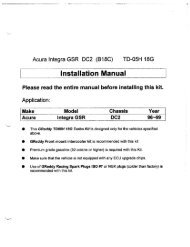
2003 Nissan 350Z (VQ35DE) Twin TD05-18G 8cm 2
Installation Manual<br />
Please read the entire manual before installing this kit.<br />
Application:<br />
Make Model Chassis Year<br />
Nissan 350Z Z33 2003<br />
• This <strong>GReddy</strong> <strong>Turbo</strong> <strong>Kit</strong> is designed only for the vehicles specified above.<br />
• <strong>GReddy</strong> Front mount intercooler kit is recommended with this kit<br />
• Premium grade gasoline (91 octane or higher) is required with this <strong>Kit</strong>.<br />
• Make sure that the vehicle is not equipped with any ECU upgrade chips.<br />
• Use of <strong>GReddy</strong> Racing Spark Plugs ISO LONG #7 or NGK plugs (colder than<br />
factory) is recommended with this kit.<br />
Important<br />
1. This installation should only be performed by a trained specialist who is very familiar with the<br />
automobile’s mechanical, electrical and fuel management system.<br />
2. If installed by an untrained person, it may cause damage to the kit as well as the vehicle.<br />
3. <strong>GReddy</strong> Performance Products Inc. is not responsible for any damage to the vehicle’s electrical<br />
system caused by improper installation.<br />
4. Make sure to follow the instruction and pay attention to the “Important”, “Warning!” and “Caution!”<br />
notice through out the instruction.<br />
5. Improper installation can be dangerous! Please make sure to inspect the installation before<br />
operating the vehicle.<br />
6. Call your <strong>GReddy</strong> Authorized dealer or <strong>GReddy</strong> Performance Products if there are any problems or<br />
questions regarding this product.
1. Parts List<br />
1. <strong>Turbo</strong>charger TD05-18G 8cm 2 2<br />
2. Wastegate (<strong>GReddy</strong> / Tial) .45bar 2<br />
3. Exhaust Manifold (Right Side) Ductile Iron Cast 1<br />
4. Exhaust Manifold (Left Side) Ductile Iron Cast 1<br />
5. Downpipe Adapter (Right Side) 1<br />
6. Downpipe Adapter (Right Side) 1<br />
7. Compression Pipe R C-1 (50∅ Aluminum Elbow No.6) 1<br />
8. “ R C-2 (50∅ Aluminum) 1<br />
9. “ R C-3 (50∅ Aluminum Elbow No.21) 1<br />
10. “ L C-4 (50∅-70∅ Aluminum) 1<br />
11. “ C-5 (50∅ Aluminum) 1<br />
12. “ C-6 (80∅ Aluminum) 1<br />
13. Airflow Meter Adapter 1<br />
14. Suction Pipe R S-1 (60∅ Aluminum) 1<br />
15. “ R S-2 (70∅ Aluminum) 1<br />
16. “ L S-3 (60∅ Aluminum Elbow No.82) 1<br />
17. “ L S-4 (70∅ Aluminum) 1<br />
18. Airinx AY-SB (Blue) 2<br />
19. Airinx Hose Adapter S70 2<br />
20. Oil Pressure Hose SUS (R=600mm, L=800mm) _________________1 each<br />
21. Oil Pressure Union Fitting 3-Way Fitting 2<br />
22. “ 1/8PT – 1/8 PT Straight 2<br />
23. “ 1/8PT – 1/8 PF Straight 1<br />
24. “ 1/8PT – 1/8 PF Male to Male 90° 1<br />
25. Oil Pressure Banjo Fitting Male and Female (small) 2<br />
26. Copper Washer 10∅ (t=1.0) 4<br />
27. Oil Return Pipe Right 16∅ 1<br />
28. Oil Return Pipe Left 16∅ 1<br />
29. Oil Pan with welded Oil Return Pipe 1<br />
30. Vacuum Hose 5∅ x 100mm (Blue) 1<br />
31. “ 6∅ x 2000mm (Blue) 1<br />
32. Radiator Reserve Hose 7∅ x 10∅ x 790mm CR60° Tube 1<br />
33. Rubber Hose 15∅ x 1140mm (Oil Return 440mm, Blow By 300mm, Power Steering 200mm) 1<br />
34. Silicone Hose 50∅ x 70mm Straight 6<br />
35. “ 80∅ x 80mm Straight 2<br />
36. “ 60∅ - 70∅ Reducer 2<br />
37. “ 60∅ - 80∅ Reducer 2
38. “ 70∅ - 80∅ Reducer 1<br />
39. Hose Band 12∅ #8 4<br />
40. “ 16∅ #10 9<br />
41. “ 50∅ #32 ____________ 12<br />
42. “ 60∅ #36 4<br />
43. “ 70∅ #44 5<br />
44. “ 80∅ #48 7<br />
45. Power Steering Pump Fitting 1<br />
46. Check Valve (Nissan factory part #47478-51E00) 1<br />
47. Radiator Reserve Tank 1<br />
48. Radiator Reserve tank Cap 1<br />
49. Hose Fitting 8∅ 90° 1<br />
50. Radiator Reserve Tank Bracket A / B 1 Set<br />
51. Aluminum Spacer t=28mm 1<br />
52. Airinx Bracket Right / Left 1 Set<br />
53. Hose Fitting 16∅ Straight 1<br />
54. Exhaust Manifold Gasket (Nissan Factory Part # 14036-AG010) 1 Set<br />
55. <strong>Turbo</strong> Gasket TD05 In / Out 4<br />
56. Catalytic Converter Gasket (Nissan Factory Part # 20813-AL500) 2<br />
57. Oil Return Gasket TD Small 2<br />
58. Thermo Cloth 100m x 1000mm 4<br />
59. Three Way fitting 5∅ - 6∅ 1<br />
60. Zip Ties 150mm 15<br />
61. E-Manage (US-Z33) 1<br />
62. “ Harrness 1<br />
63. “ I/J Harness 1<br />
64. “ RPM signal adapter 1<br />
65. Injectors 440cc (with 4 aluminum fuel rail spacers) 6<br />
66. M5 x 15mm Stainless P=0.8 B S/W F/W N 1<br />
67. M6 x 15mm Stainless P=1.0 B S/W - - 6<br />
68. M6 x 15mm Stainless P=1.0 B S/W F/W N 5<br />
69. M6 x 40mm Steel P=1.0 B - - - 1<br />
70. M8 x 15mm Stainless P=1.25 B S/W - - 6<br />
71. M8 x 20mm Stainless P=1.25 B S/W - - 2<br />
72. M8 x 25mm Stainless P=1.25 B S/W - - 4<br />
73. M8 x 30mm Stainless Stud P=1.25 – 1.25 B S/W - N 8<br />
74. M10 x 35mm Stainless Stud P=1.25 – 1.25 B S/W - N____ 12<br />
75. M10 x 45mm Stainless Stud P=1.25 – 1.50 B - - - 2
1. Parts List<br />
1 2 3 4<br />
5 6 7 8<br />
9 10 11 12<br />
13 14 15 16<br />
17 18 19 20
1. Parts List<br />
21 22 23 24<br />
25 26 27 28<br />
29 30 - 33 34 - 38 39 - 40<br />
45 46 47 48<br />
49 50 51 52
1. Parts List<br />
53 54 55 56<br />
57 58 59 60<br />
61 62 63 64<br />
65 66 - 75
2. Factory Parts Removal<br />
When removing the stock parts, make sure you read over the<br />
factory repair manual for proper procedures.<br />
2-1 Disconnect the negative terminal of the battery.<br />
2-2 Drain the engine oil, coolant and power steering fluid.<br />
2-3 Disconnect the air flow meter.<br />
2-4 Remove the Air cleaner assembly with airflow meter, intake tube, and breather<br />
hose.<br />
2-5 Remove the Top Radiator Hose and the Water Pipe (Located above the Right<br />
Exhaust manifold).<br />
2-5 Disconnect the primary and secondary O2 sensor and remove the exhaust<br />
manifold and catalytic converter.<br />
2-6 Remove the exhaust manifold.<br />
2-7 Remove oil pan (Please refer to the factory service manual for detail instructions f<br />
or removing the oil pan.)<br />
2-8 Remove the upper intake manifold collector, fuel rail assembly with injectors and<br />
regulator.
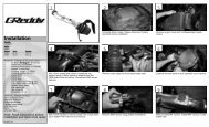
3. <strong>Turbo</strong> <strong>Kit</strong> Installation<br />
Thermo Cloth Installation<br />
• Remove the bracket securing the fuel line right below the right side shock tower and<br />
disconnect the fuel line. Flip the connector so that the line points up and reconnect the<br />
line. Double wrap the fuel and evap Line using safety Wire. Leave the top bracket off<br />
and secure the bottom back on as shown.<br />
(Parts used #58)<br />
(This picture shows the turbo already installed)<br />
Important!<br />
• Make sure that the fuel line is secured away from the turbine housing when the<br />
turbo is installed. Some bending of the lines is necessary to achieve good<br />
clearance.<br />
• Make sure the lines are properly wrapped twice.<br />
• Make sure to use safety wire to wrap the thermo cloth. Zip ties will melt from the<br />
heat and eventually will come off.<br />
• Make sure that the fuel line connector is properly clicked in all the way.<br />
• <strong>GReddy</strong> Performance Products, Inc. will not be responsible for any damage<br />
caused due to improper installation.
Caution!<br />
• Make sure to check and double check this step. This is the most important<br />
step in this install.<br />
• Without proper clearance and thermo wrapping the fuel lines, the fuel line<br />
connector can melt from heat and may catch on fire.<br />
• Wrap the Starter and the Main Engine<br />
harness right above the transmission bell<br />
housing.<br />
Important!<br />
Make sure that the main engine harness is<br />
properly wrapped and secured away from the<br />
manifold and the wastegate when they are<br />
installed.<br />
Caution!<br />
Without proper clearance and thermo wrapping the harness, it melt and cause a short<br />
in the electrical system or may catch on fire.<br />
Power Steering Line Installation<br />
1. Remove the hose fitting off the power<br />
steering pump and install the provided<br />
fitting.<br />
(Parts Used #40, 45)<br />
2. Cut the provided 15∅ hose to 200mm (8in)<br />
and install it between the pump and the<br />
tank.<br />
(Parts Used #33)<br />
Oil Pan Installation<br />
Install the Oil pan with a silicone sealant.<br />
(Part Used #29)
Oil Pressure Line Installation<br />
Install the oil pressure line to engine block using provided fittings.<br />
(Part Used #20, 21, 22, 23, 24)<br />
600mm line is for the right side and 800mm line is for the left side.<br />
Exhaust Manifold Installation<br />
1. Remove all factory exhaust manifold stud bolt off from the cylinder head. Install the<br />
provided M10 x 35mm stud bolts on to the cylinder head as shown.<br />
(Part Used #74)<br />
Install Stud Bolt<br />
Install Stud Bolt<br />
Front of<br />
the engine<br />
Front of<br />
the engine<br />
Left Side (Driver’s Side)<br />
Right Side (Passenger’s Side)<br />
2. Install the Exhaust Manifold using provided gasket and hardware.<br />
(Part Used #3, 4, 54, 74)<br />
Left Side (Driver’s Side)<br />
Right Side (Passenger’s Side)
<strong>Turbo</strong>charger Installation<br />
1. Install the turbocharger on to the exhaust manifold installed in the previous step.<br />
* For the left side, remove the steering shaft joint before installing the turbo.<br />
* For the right side, remove the bolts holding the starter, and lower the starter before<br />
installing the turbo. (Part Used #1, 25, 26, 55, 71, 72,<br />
73)<br />
Check<br />
• After the turbo installation, double check the fuel line clearance by the turbo and the<br />
manifold on right side (passenger side).<br />
2. Connect the Oil Pressure line to the turbo using the provided banjo fitting.<br />
(Parts Used #25)<br />
Oil Return Pipe Installation<br />
Install the oil return pipe using provided gasket and hardware. Cut the provided 15∅<br />
hose to proper length and install them between the oil return pipe and the oil pan as<br />
shown. (Part Used #27, 28,33,<br />
40, 57, 67)<br />
Left Side (Driver’s Side)<br />
Right Side (Passenger’s Side)
Wastegate Installation<br />
Install the provided banjo fitting on to the bottom port of the wastegate. (Top Port is used<br />
for boost controller) Install the wastegate using the provided gasket and hardware as<br />
shown. (Part Used #2, 73)<br />
Left Side (Driver’s Side)<br />
Right Side (Passenger’s Side)<br />
• Double check the clearance between the wastegate and the main engine harness on<br />
the right side (passenger side). Make sure that there is enough clearance to avoid the<br />
harness from getting to hot and melting.<br />
Down Pipe Adapter Installation<br />
Install the down pipe adapter using the provided gasket and hardware as shown.<br />
(Part Used #5, 6, 55, 70, 72)<br />
Exhaust System Installation<br />
Install the catalytic converter and the exhaust<br />
system using the provided gasket and hardware<br />
as shown.<br />
(Part Used #56, 75)
Vacuum hose for Wastegate Installation<br />
Remove the factory engine cover. Locate the<br />
rubber plug on the intake manifold and remove it.<br />
Connect the 5∅ hose to the intake manifold and<br />
by using the three way fitting and connect the 6∅<br />
hose to each of the wastegate fitting.<br />
(Part Used #30, 31, 59)<br />
Suction Pipe Installation<br />
1. Install the Airinx air filter to the Suction pipe S-2 and S-4.<br />
(Part Used #14, 15, 16, 17, 18, 19, 33, 36, 37, 40, 42, 43, 44, 52, 53, 67)<br />
2. Install the S-1 and the S-2 (with AIRINX) to the right (passenger side) turbo inlet using<br />
provided hose and hose clamps and secure the Airinx to the chassis as shown. Bend<br />
the Power steering line over towards the pulley so that the S-2 clears the line.<br />
Bend Away<br />
Airinx<br />
Bracket<br />
3. Install the S-3 and the S-4 (with AIRINX) to the left (driver side) turbo inlet using<br />
provided hose and hose clamps and secure the Airinx to the chassis as shown. Bend<br />
the A/C line toward the engine so that the S-4 pipe clears the line.<br />
Bend A/C<br />
Line<br />
Airinx<br />
Bracket
Compression Pipe Installation<br />
1. Install the Air flow meter adapter on tot he air flow meter.<br />
2. Install the Compression pipe C-1, C-2, C-3, C-4, C-5, and C-6 by using the provided<br />
hose and hose clamps as shown. Make sure to check all the clearance before<br />
securing the hose clamps.<br />
* When installing the airflow meter assembly, make sure not to reverse the flow.<br />
(Part Used #7, 8, 9, 10, 11, 12, 13, 34, 35, 38, 41, 43, 44, 66, 67)<br />
Secure the bracket on C-3 to the block<br />
Secure the bracket on C-6 to the Intake manifold<br />
Radiator Over Flow Tank Installation<br />
Remove the left side head light assembly, and Install the provided radiator over flow tank<br />
as shown. Connect the hose to the lid and reinstall the head light assembly.<br />
(Part Used #47, 48, 49, 50, 52, 68, 69)
Brake Check Valve Installation<br />
Install the provided check valve as shown.<br />
(Part Used #39, 46)<br />
Injectors Installation<br />
1. Remove the upper intake manifold collector, fuel rail assembly with injectors and<br />
regulator.<br />
2. Grind the top of the fuel rail as shown to clear the intake manifold.<br />
Make sure not to grind too much. Grind the part on the bracket that is raised down flat.<br />
Clean the rail thoroughly after grinding.<br />
3. Install the 440cc injectors and reinstall the fuel rail using the provided spacer.<br />
(Part Used #65)<br />
4. Cut the factory injector connectors and solder in the provided connector harness.<br />
How to solder<br />
1Strip the end of wires<br />
2 Twist the end together<br />
3 Solder the wires<br />
(Make sure to solder<br />
Completely)<br />
4 Tape up the soldered area
E-manage Installation<br />
Install the e-manage and the rpm adapter as shown in the diagram. Make sure to solder all<br />
connections except for the ones that are supplied with the male and female connectors.<br />
(Part Used #61, 62, 63, 64)<br />
Important!<br />
• Make sure you fully understand the diagram before attempting this installation.<br />
• Improper wiring can damage the ECM and the vehicle's electrical system.<br />
• <strong>GReddy</strong> Performance Product, Inc. will not be responsible for any damage caused by<br />
improper installation.<br />
• Please do not use crimp connectors or t-tap connectors. These can cause poor<br />
connection and prevent e-manage to operate properly.
E-manage Installation<br />
Z33 ECM HARNESS CONNECTOR<br />
4 5<br />
3<br />
1 2<br />
24 23 22 21 20 19 18 17 16 15 14 13 12 11 10 9 8 7 6<br />
43 42 41 40 39 38 37 36 35 34 33 32 31 30 29 28 27 26 25<br />
62 61 60 59 58 57 56 55 54 53 52 51 50 49 48 47 46 45 44<br />
81 80 79 78 77 76 75 74 73 72 71 70 69 68 67 66 65 64 63<br />
106 107 108 109 110 111 112 113<br />
98 99 100 101 102 103 104 105<br />
90 91 92 93 94 95 96 97<br />
82 83 84 85 86 87 88 89<br />
119 120 121<br />
117 118<br />
114 115 116<br />
61<br />
62 60<br />
22<br />
23 21<br />
119<br />
RPM(Y)<br />
18-5 (BL/R)<br />
Connector<br />
RPM(Y)<br />
18-7 (Y/R)<br />
Male Female<br />
18-13 (R)<br />
RPM(Y)<br />
18-16 (PI/R)<br />
Splice<br />
18-10(G)<br />
RPM(Y)<br />
18-17(LB/R)<br />
18-3(W)<br />
RPM(Y)<br />
18-8(PL/R)<br />
18-12 (B)<br />
RPM(Y)<br />
18-18(B/R)<br />
18-6(O/R)<br />
1<br />
81 79<br />
80<br />
42 40<br />
41<br />
51 116<br />
Color Code: W - White, G - Green, B - Black, BL - Blue, BR - Brown, R - Red, GR - Grey, PL - Purple,<br />
Y - Yellow, O - Orange, LB - Light Blue, PI - Pink
E-manage Installation<br />
I/J Harness (18Pin)<br />
* Looking at harness side.<br />
e-manage<br />
Factory ECU<br />
Pin # Wire Color Description ECU Pin # Color Code<br />
3 White MAP IN 51<br />
Orange Airflow<br />
(harness Side)<br />
5 Blue/<br />
Red<br />
INJ 1 23 Red/<br />
Black<br />
6 Orange/ INJ 2 42 Black/<br />
Red<br />
Red<br />
7 Yellow/ INJ 3 22 Red/<br />
Red<br />
Yellow<br />
8 Purple/ INJ 4 41 White/<br />
Red<br />
Red<br />
Meter<br />
INJ 1<br />
INJ 2<br />
INJ 3<br />
INJ 4<br />
10 Green MAP<br />
OUT<br />
51 (ECU side) Orange Airflow<br />
Meter<br />
11 brown RPM RPM Brown<br />
Adapter<br />
12 Black GND 116 Black/<br />
Red<br />
ECM<br />
ground<br />
13 Red +B 119 Green/<br />
Yellow<br />
ECM<br />
Power<br />
16 Pink/Red INJ 5 21 Sky blue INJ 5<br />
17 Light Blue/ INJ 6 40 Light INJ 6<br />
Red<br />
green<br />
18 Black/<br />
Red<br />
INJ GND 1 Black ECM<br />
ground<br />
Sensor Adapter<br />
Connect to<br />
Wire Color Description Pin # Color Code<br />
Yellow RPM IN 60 ECU PU/ W IG#5<br />
Yellow RPM IN 61 ECU L/R IG#3<br />
Yellow RPM IN 62 ECU Y/R IG#1<br />
Yellow RPM IN 79 ECU GY/R IG#6<br />
Yellow RPM IN 80 ECU GY IG#4<br />
Yellow RPM IN 81 ECU G/b IG#2<br />
Brown<br />
Black<br />
RPM OUT 18 - 11 Brown RPM<br />
e-manage<br />
GND<br />
116 ECU<br />
Black/Red<br />
ECM<br />
Ground
Starting the Engine<br />
1. Refill the engine oil to factory spec.<br />
2. Check all the hoses and wires connection, then reconnect the negative side of the<br />
battery.<br />
3. Turn the ignition to “ON” position 2-3 times to get fuel pressure. Then, check the<br />
injectors and the fuel rail for any fuel leaks.<br />
* Repair any fuel leaks before starting the engine. Starting the engine with a<br />
fuel leak can cause fire in the engine compartment and can be very<br />
dangerous.<br />
4. Remove the ECM fuse and crank the engine to get oil pressure to the turbo. (Until the<br />
oil light on the dash turns off) Check for any oil leaks, then reinstall the fuse and start<br />
the engine.<br />
5. While idling, check for any oil, coolant, or air leeks.<br />
6. After inspection, reinstall the under cover and other stock parts that was removed.<br />
7. On the initial run, be sure to have a boost gauge to check the turbo-actuator setting.<br />
This turbo kit is preset to boost between 0.4kg/cm 2 to 0.45kg/cm 2 .<br />
It is very important that you monitor the boost pressure, and make sure not to over<br />
boost. Over boosting can cause engine damage.<br />
This completes the <strong>Turbo</strong> <strong>Kit</strong> installation.<br />
Important!<br />
• It is very important that you monitor the boost pressure, and make sure not to<br />
over boost. Over boosting can cause engine damage.<br />
• <strong>GReddy</strong> Performance Products, Inc. is not responsible for any engine damage<br />
caused by over boosting (increased boost), modification to the kit, and/or<br />
misuse of the product. NO WARRANTY is offered.<br />
• Due to lack of control over proper installation and use of this product,<br />
NO WARRANTY is offered for this kit.
e-manage Information<br />
Important!<br />
• The e-manage included in this kit is preprogrammed for the this turbo kit.<br />
• Do not attempt to adjust any of the setting in the e-manage.<br />
• Any adjustments made can cause damage to the e-manage, engine and the<br />
factory ECU.<br />
Important!<br />
As of 11/25/03 this kit is not a street legal kit. Please ignore the label on the<br />
e-manage.<br />
ACTIVE L.E.D.<br />
(2) When the ignition is turned on, it will illuminate and flash GREEN.<br />
(3) When it reaches to the A.A.V. setting RPM range, it will illuminate and flash ORANGE.<br />
(4) When an error is detected it will flash RED.<br />
INTERACTION L.E.D.<br />
1. This will illuminate when there is a connection with PC.<br />
Checking Error Codes<br />
When the unit is powered up and if there are any errors, the ACTIVE L.E.D will turn<br />
“RED” from “GREEN”, and begin to flash.<br />
If this happens shut the engine off and turn the ignition switch to “ON”<br />
position to go to Self Troubleshooting Mode. While in the Self<br />
Troubleshooting Mode, the L.E.D. will show the error code. Turn off the<br />
ignition. Check the error code in the chart below and fix the problem.<br />
The error code will show until the error is corrected.