Paper - OpenFlipper
Paper - OpenFlipper
Paper - OpenFlipper

Create successful ePaper yourself
Turn your PDF publications into a flip-book with our unique Google optimized e-Paper software.
Visual Comput (2006)<br />
DOI 10.1007/s00371-006-0050-2 ORIGINAL ARTICLE<br />
Darko Pavić<br />
Volker Schönefeld<br />
Leif Kobbelt<br />
Interactive image completion with<br />
perspective correction<br />
© Springer-Verlag 2006<br />
D. Pavić (✉) · V. Schönefeld · L. Kobbelt<br />
Computer Graphics Group, RWTH Aachen<br />
University, Germany<br />
{pavic, kobbelt}@cs.rwth-aachen.de<br />
Abstract We present an interactive<br />
system for fragment-based<br />
image completion which exploits<br />
information about the approximate<br />
3D structure in a scene in order<br />
to estimate and apply perspective<br />
corrections when copying a source<br />
fragment to a target position. Even<br />
though implicit 3D information is<br />
used, the interaction is strictly 2D,<br />
which makes the user interface very<br />
simple and intuitive. We propose<br />
different interaction metaphors in our<br />
system for providing 3D information<br />
interactively. Our search and matching<br />
procedure is done in the Fourier<br />
domain, and hence it is very fast and<br />
it allows us to use large fragments<br />
and multiple source images with<br />
high resolution while still obtaining<br />
interactive response times. Our image<br />
completion technique also takes<br />
user-specified structure information<br />
into account where we generalize the<br />
concept of feature curves to arbitrary<br />
sets of feature pixels. We demonstrate<br />
our technique on a number of difficult<br />
completion tasks.<br />
Keywords Image completion ·<br />
Image repair · Example-based<br />
synthesis · User interface<br />
1 Introduction<br />
Fragment-based image completion techniques are a very<br />
powerful tool to fill in missing pixel information, e.g.,<br />
when removing a foreground object from a digital photo.<br />
The conceptual idea is to fill a hole in the image by copying<br />
small source fragments from known regions of the<br />
image such that they eventually completely cover the undefined<br />
region. The mutual overlap of the target fragments<br />
and the overlap between target fragments and the boundary<br />
of the hole is used to compute a similarity measure<br />
which controls the selection of the best source fragment<br />
candidate in order to guarantee a seamless appearance of<br />
the completed image.<br />
The various approaches to fragment-based image completion<br />
mainly differ in three aspects. First, in the definition<br />
of the search space. Source fragments can be taken<br />
anywhere from the source image or only from certain userdefined<br />
sub-regions in order to preserve specific feature<br />
information or to reduce time complexity. Second, the selection<br />
of the best source fragment is based on a similarity<br />
measure, which can use pixel color information as well as<br />
structural information such as the presence and orientation<br />
of image features. Third, once the best source fragment<br />
is found, it has to be transformed to the target location in<br />
the image. Besides mere translation, certain types of affine<br />
transforms, like scaling and rotation, have been proposed.<br />
The fundamental assumption, which justifies the fragment-based<br />
image completion approach, is that for a small<br />
enough image fragment, we can assume the scene, which<br />
is visible in this fragment, to be planar. Hence we can ignore<br />
all kinds of occlusion and dis-occlusion effects when<br />
copying a fragment from one image location to another,<br />
and therefore we do not need any true 3D information<br />
about the scene. However, the restriction to affine transforms<br />
of the fragments, as it has been done in the previous<br />
work, mathematically corresponds to the even more strict<br />
and somewhat unrealistic assumption that these planar<br />
scene fragments are aligned to the image plane. A natu-
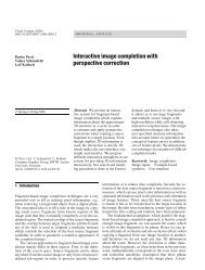
D. Pavić etal.<br />
Fig. 1a–e. The effect of perspective corrections<br />
for image completion. a shows<br />
the input image. d shows the completion<br />
without using perspective correction<br />
which leads to strong perspective artifacts.<br />
When using the rectifying homography<br />
defined in b and then performing the completion<br />
in the rectified space c we obtain<br />
the solution in e<br />
ral generalization of the existing approaches is, therefore,<br />
to allow for projective transforms of the image fragments,<br />
which enables the compensation of perspective distortion<br />
when the source and target scene fragments are not lying<br />
in the same supporting 3D plane.<br />
In this paper we present a new system for interactive<br />
image completion that applies perspective corrections<br />
when copying fragments. Through a simple interaction<br />
metaphor the user can define a set of projective transforms.<br />
Based on this information the system rectifies the<br />
corresponding image regions and then performs the image<br />
completion in rectified image space. An intuitive extension<br />
of this user interface allows the system to handle<br />
even more complex scene geometries such as moderately<br />
curved surfaces. An automatic snapping mechanism for<br />
the points selected by the user guarantees continuity at the<br />
boundaries of adjacent rectified regions. User-defined feature<br />
information is taken into account by encoding feature<br />
proximity as an additional color channel to the image.<br />
Figure 1 shows a simple example for an application of<br />
our interaction metaphor and the resulting image completion<br />
which is free from perspective artifacts. In the results<br />
Sect. 9 we present more examples, which demonstrate the<br />
power and usefulness of our system.<br />
2 Related work<br />
There are two fundamental approaches to image completion:<br />
image inpainting methods and example-based approaches.<br />
Image inpainting [3, 5, 6, 28] is good in filling<br />
small missing areas like thin gaps, e.g., when removing<br />
scratches from old photographs, but the diffusion process<br />
of image inpainting leads to blurring artifacts when trying<br />
to complete large missing areas, e.g., after removing large<br />
foreground objects from images.<br />
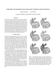
Example-based approaches have their origin in texture<br />
synthesis, where large texture patches are synthesized<br />
from small texture samples on a per-pixel basis using<br />
a pixel neighborhood for color prediction [2, 14, 32]. Instead<br />
of this per-pixel procedure some approaches use<br />
larger patches or fragments [13, 25] in order to speed up<br />
the process. By using graph-cut techniques [24], optimal<br />
boundaries between patches can be computed.<br />
In the context of image completion there are some<br />
approaches working on a per-pixel basis [7, 16, 20], but<br />
fragment-based approaches [4, 9, 12, 31] usually produce<br />
superior results. The automated method presented by<br />
Drori et al. [12] leads to very impressive completions but<br />
at the cost of high computation time. Our method achieves<br />
results of comparable quality but it is up to two orders<br />
of magnitude faster allowing for interactive control of the<br />
process.<br />
An important observation for image completion is that<br />
the propagation of structure should be treated separately<br />
from texture propagation [7, 9]. Recently Sun et al. [31]<br />
presented an interactive approach, where feature curves<br />
for structure propagation are supplied by the user. Putting<br />
a human user into the loop usually leads to much more<br />
plausible completions than the ones generated by sophisticated<br />
heuristics. Hence user-control is considered an important<br />
feature. In our system the user also has the possibility<br />
to specify structure information as additional color<br />
channel to the image.<br />
Other previous completion techniques take user-defined<br />
points of interest [12] into account to control the propagation<br />
direction when completing rotationally symmetric
Interactive image completion with perspective correction<br />
shapes. Depth images have also been used to restrict the<br />
search for source fragments to regions of similar depth<br />
in order to avoid artifacts emerging from perspective distortion<br />
[16, 30]. Wilczkowiak et al. [33] have mentioned<br />
perspective correction but not really explored it in the<br />
context of image hole filling. In this paper the perspective<br />
correction is investigated much more thoroughly and<br />
explained in detail so that it can be reproduced easily.<br />
Moreover, we embed it into an easy-to-use interactive<br />
workflow and generalize it to continuous piecewise homographies,<br />
which enables the rectification of more complex<br />
scene geometries.<br />
There are also a number of papers where non-greedy<br />
methods are used. Kwatra et al. [23] propose a global<br />
texture optimization and very recently Komodakis and<br />
Tziritas [22] proposed a global optimization method for<br />
image completion. However they also do not consider<br />
the problem of perspective distortion and show only lowresolution<br />
examples.<br />
Our approach is also somewhat related to methods<br />
from the field of image-based modeling and editing [11,<br />
19, 27], where user interaction to supply 3D information<br />
about the underlying scene is a very important part of<br />
the workflow. Oh et al. [27] represent a scene as a layered<br />
collection of depth images, which are created manually.<br />
Horry et al. [19] generate animations from single images<br />
by providing perspective information through a vanishing<br />
point and a spidery mesh. Debevec et al. [11] describe<br />
hybrid approach combining image-based and geometrybased<br />
modeling metaphors for the reconstruction of architecture.<br />
Drawing quads to convey perspective information has<br />
been used in other image processing applications before.<br />
But embedding this metaphor as well as the quad-grid<br />
metaphor in the interactive image completion workflow is<br />
new. Liu et al. [26] use the quad-grid metaphor to manually<br />
tag the periodicity of a non-planar texture sample and<br />
typically several repetitions of the underlying pattern have<br />
to be selected. In our case, we use it to define piecewise<br />
homographies for the rectification of non-planar surfaces.<br />
The technical contribution lies in a relaxation procedure to<br />
ensure continuity between the homographies, i.e., to ensure<br />
that there are no jumps between neighboring facets.<br />
Without this snapping technique the metaphor would not<br />
be practical since the user would have to click image positions<br />
to sub-pixel precision.<br />
Our interactive system uses several image buffers as<br />
source buffers S(·, ·). When searching for fragments, one<br />
buffer is set as the target buffer T(·, ·). Since all buffers are<br />
treated the same, our system explicitly supports scenarios<br />
where an image is completed by transforming source<br />
fragments from several other input images.<br />
As already stated in the introduction, fragment-based<br />
image completion techniques make the assumption that<br />
the scene is locally (within one fragment) flat such<br />
that copying fragments becomes essentially a 2D operation.<br />
The restriction to affine transformations of fragments<br />
(shifting, scaling, rotation) as done in previous<br />
approaches, further assumes that all planar fragments are<br />
aligned to the image plane. This, however, is not the case<br />
in most scenes.<br />
We, therefore, generalize previous approaches by taking<br />
the estimated 3D orientation of the flat fragments into<br />
account. The basic idea is to rectify image regions by applying<br />
projective transforms to the input image(s). The<br />
term rectification refers to a 2D transform which aligns arbitrary<br />
3D planes to the image plane. To copy a fragment<br />
from one rectified image to another then corresponds to<br />
applying a projective transform to the fragment.<br />
The workflow of our system is as follows: After loading<br />
the input image(s) the user first paints an α-matte<br />
which defines the image regions to be replaced (α = 1).<br />
Then he can define a set of 3D planes in the image which<br />
are used for rectification. Each rectification generates another<br />
image buffer where we can later search for source<br />
fragments. If no 3D plane is specified, our system behaves<br />
just like previous image completion techniques without<br />
perspective corrections. Optionally, the user can further<br />
define a set of features (lines, curves, or arbitrary sets of<br />
pixels) which will be used to restrict the source fragment<br />
search in order to preserve these features.<br />
After the specification phase, the user interactively<br />
picks target fragment locations (usually near the boundary<br />
of the undefined region) and chooses target fragment<br />
sizes, and the system finds the best fitting source fragment.<br />
By this the unknown region (α = 1) is incrementally filled<br />
with fragments. Since we use a FFT-based approach for<br />
the searching procedure, the response times of our system<br />
are fractions of a second even if we search for large fragments<br />
in high-resolution source buffers.<br />
Notice that even if we are implicitly using 3D information,<br />
the user interface is completely 2D. The user only<br />
draws curves or picks locations on 2D images. In the following<br />
sections we will explain which intuitive interaction<br />
metaphors make this possible.<br />
3 Overall system description<br />
4 Image completion with perspective correction<br />
Since the input image and the rectified source buffers are<br />
related by known perspective transforms, we can apply the<br />
same transformations to the α-matte and hence the roles of<br />
source and target buffers can be exchanged in the image<br />
completion phase.
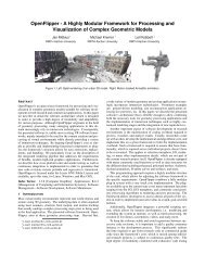
D. Pavić etal.<br />
Fig. 2a–c. Homographies (or 3D planes)<br />
are defined by drawing convex quads directly<br />
in the image (a). These quads are<br />
mapped to rectangles with a user-specified<br />
aspect ratio (b, c). Each rectified image<br />
serves as an additional image buffer. The<br />
quads do not have to bound the rectified<br />
region as shown in c<br />
Due to their rotational invariance, we prefer to use circular<br />
fragments. When applying a projective transform,<br />
such a fragment would be mapped to an ellipse which<br />
would make fragment matching computationally more involved<br />
(and less intuitive). However, we can exploit the<br />
freedom to switch the target buffer and to use an individual<br />
source buffer for each rectified region in order to avoid<br />
the use of elliptical fragments.<br />
Assume we had a circular planar fragment in 3D object<br />
space (e.g., one of the circles on the sides of the cube<br />
in Fig. 2) which is mapped to an ellipse in image space<br />
(the input image (a)). Rectifying the supporting plane (the<br />
side of the cube) corresponds to aligning the fragment to<br />
the camera plane such that it becomes circular in the distorted<br />
image (subfigures (b) and (c)). Hence if we restrict<br />
the selection of target fragments to the rectified region of<br />
the target buffer and the source fragment search to the rectified<br />
regions of the source buffers then circular fragments<br />
are always mapped to circular fragment since they, in fact,<br />
correspond to circular fragments in 3D object space. The<br />
perspective distortion of the fragment then becomes effective<br />
only when the completed region is mapped back to<br />
the input image by un-rectifying the target buffer.<br />
In practice it turns out that we do not even have to explicitly<br />
restrict the fragment search to the rectified regions<br />
since the most similar fragment is usually found in this<br />
region anyway. Due to the fact that we are using a FFTbased<br />
evaluation procedure, the unsuccessful search in the<br />
distorted regions is faster than explicitly checking whether<br />
a given source fragment belongs to the rectified region.<br />
Moreover, as shown in the Colosseum example in Fig. 9,<br />
it is not needed to rectify the whole missing region explicitly.<br />
5 Sketching a homography<br />
While the surface of real objects in a 3D scene can often<br />
be assumed to be locally planar, their surface orientation<br />
is usually not aligned to the image plane of the camera.<br />
Hence when copying fragments we have to compensate<br />
the perspective distortion by applying a projective transformation.<br />
Notice that even if we implicitly exploit 3D<br />
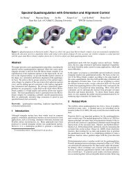
Fig. 3a,b. Quad-Grid interaction metaphor. Curved surfaces can be<br />
rectified by defining a regular quad grid as shown in a. Rectifying<br />
each quad and putting the resulting rectangles together yields an<br />
unfolded orthogonal view of the surface as visualized in b<br />
information for this operation, a projective transformation<br />
of a plane is essentially a 2D transform, a homography,<br />
which can be represented by a 3 × 3 matrix in homogeneous<br />
coordinates.<br />
The most natural way to define a homography is<br />
through a pair of quadrilaterals in image space. The four<br />
2D point correspondences provide the eight constraints by<br />
which the nine entries of the 3×3 matrix can be computed<br />
up to a constant factor (which establishes uniqueness in<br />
homogeneous coordinates) [17].<br />
In our system the user does not want to specify an arbitrary<br />
homography but a homography which is supposed<br />
to rectify an image region whose 3D pre-image is sufficiently<br />
planar. Hence it suffices that the user defines just<br />
one convex but otherwise general quad while the second<br />
quad is restricted to be a rectangle where the user only has<br />
to adjust the aspect ratio. This leads to a very intuitive user<br />
interface where the user simply draws a quad directly onto<br />
the image. The shape of the quad should be such that it<br />
covers an image region which corresponds to a rectangular<br />
3D pre-image. Figure 2 shows an example of this interaction.<br />
Notice that since the fragment search is always applied<br />
to the full image buffer, there is no need to use the homography<br />
defining quad as a clipping frame and to consider<br />
only the interior of the quad as the rectified region. In practice<br />
it is very unlikely that a matching circular fragment is<br />
found in the non-rectified region (region not parallel to the<br />
image plane after the rectification) and hence we do not
Interactive image completion with perspective correction<br />
need to explicitly segment the input image into planar regions.<br />
This observation is extremely helpful since we can,<br />
e.g., use a single window of a building to define the homography<br />
for the entire facade.<br />
6 More complex interaction metaphors<br />
When dealing with more complex scenes that contain even<br />
curved surfaces like cylinders it can become tedious to<br />
manually define all the homographies for each small part<br />
of the surface. Hence we implement another interaction<br />
metaphor which allows us to define a whole grid of quads<br />
Q i, j in an efficient manner. Each of the quads in the grid<br />
implies a homography H i, j which rectifies the interior of<br />
Q i, j . Putting all these rectified pieces together yields an<br />
unfolded orthogonal view of the whole curved surface (see<br />
Fig. 3). Unlike Liu et al. [26] we do have not to cover exactly<br />
one texture element with each quad of the grid (see<br />
Fig. 4 or Colosseum example in Fig. 9).<br />
The idea is to generate a regular quad grid by first selecting<br />
a polygon with n vertices and then offsetting this<br />
polygon to generate a n × m grid of vertices p i, j . Groups<br />
of vertices can be selected and shifted simultaneously to<br />
quickly align the quads to the perceived 3D orientations<br />
(see the accompanying video [29]).<br />
While this metaphor allows even untrained users to<br />
quickly generate a rough approximation of a consistent<br />
Fig. 4a–d. Quad-Grid relaxation. a shows the initial constellation<br />
of the quad-grid points. The piecewise homographies cause discontinuities<br />
at the common boundaries (b). c visualizes the same<br />
constellation after our relaxation procedure which eliminates the<br />
discontinuities as shown in d. The remaining distortions in the interior<br />
of the quads are due to the piecewise linear approximation of<br />
the cylindrical surface<br />
quad mesh, it turns out to be quite difficult to position<br />
the vertices with a sufficient precision such that the rectified<br />
image is a continuous deformation of the input image<br />
(see Fig. 4). The reason for this difficulty is that even if<br />
the homographies H i, j are defined by the common corners<br />
{p i, j , p i+1, j , p i, j+1 , p i+1, j+1 } of the quads Q i, j there is<br />
no guarantee that the homographies of two neighboring<br />
quads, e.g., H i, j−1 and H i, j coincide on the whole common<br />
boundary edge p i, j p i+1, j . Geometrically this is obvious<br />
since for an arbitrary pair of 2D quads there does<br />
not have to exist a spatial configuration of two 3D rectangles<br />
and a perspective mapping which projects the 3D<br />
rectangles to the 2D quads.<br />
To make the quad grid metaphor less sensitive, we derive<br />
a snapping mechanism which drags the grid defined<br />
by the user to a nearby configuration satisfying the property<br />
that homographies belonging to neighboring quads<br />
are continuous along the common boundary edge.<br />
For simplicity let us assume that the rectified quads<br />
are squares, i.e., H i, j (Q i, j ) =[i, i + 1]×[j, j + 1]. From<br />
projective geometry we know that two homographies are<br />
identical along a line if they agree on at least three points<br />
along that line [8]. Since by construction neighboring homographies<br />
H i, j−1 and H i, j coincide at the common corner<br />
points p i, j and p i+1, j , we can measure the inconsistency<br />
by looking at how strongly the two mappings deviate<br />
at the mid-point of the common edge (see Fig. 5).<br />
Because our snapping mechanism adjusts the positions<br />
of the grid vertices p i, j , it is better to compute<br />
the deviation in image space and to consider the<br />
inverse homographies Hi, −1<br />
j<br />
which map unit squares<br />
[i, i + 1]×[j, j + 1] to image quads Q i, j . For these the<br />
mid-point deviation on the edge p i, j p i+1, j is computed<br />
by ‖Hi, −1<br />
j−1 (i + 1 2<br />
, j) − H−1<br />
i, j (i + 1 2<br />
, j)‖. For a given grid<br />
point p i, j we can sum up these mid-point deviations for all<br />
adjacent edges p i, j p i±1, j±1 which gives us a quality score<br />
for this vertex.<br />
Our grid snapping procedure is now a simple iterative<br />
relaxation procedure which moves each vertex in a direction<br />
which reduces its quality score. Since the procedure<br />
is quite fast there is no need for aggressive optimization.<br />
Hence we simply check for each vertex if moving it in<br />
one of the 8 principal directions improves the local quality<br />
and iterate over all interior vertices (Fig. 5). The boundary<br />
vertices are kept fixed to impose proper boundary conditions.<br />
Even if there is no strict mathematical guarantee for<br />
the convergence of this non-linear optimization, in practice<br />
the snapping procedure always worked robustly and<br />
quickly converged after only a few iterations.<br />
Our quad-grid metaphor is much more flexible than<br />
letting the user specify a cylinder mapping since we can<br />
handle more complex non-planar configurations (see e.g.,<br />
Fig. 9 top right). Also, defining a cylinder requires placing<br />
an arbitrarily oriented ellipse on the image, which is<br />
a more involved interaction than just clicking a number of<br />
points.
D. Pavić etal.<br />
Fig. 5. Quad-Grid snapping. Midpoints of<br />
neighboring squares in rectified space (circles<br />
in the right image) are not necessarily<br />
mapped to the same point in image space<br />
(depicted by the half-circles on the left).<br />
Our snapping technique searches for the<br />
best update of each grid-point p i, j in order<br />
to minimize the sum of midpoint deviations<br />
7 Feature handling<br />
As recently suggested by Sun et al. [31], feature preservation<br />
is an important aspect in image completion. Instead<br />
of adapting their technique, which uses continuous feature<br />
curves, we use an alternative pixel-based approach which<br />
nicely fits into our FFT-based computation (see Sect. 8)<br />
without causing significant overhead.<br />
In our setting a feature is an arbitrary set of pixels<br />
that can even consist of several connected components.<br />
To define a feature, the user simply draws lines or freehand<br />
curves onto the image or paints complete regions<br />
(see Fig. 9).<br />
For each feature we compute a distance map where<br />
every pixel stores its Euclidian distance to the nearest feature<br />
pixel. We set the distance map resolution to the image<br />
buffer resolution and apply the homographies to the features<br />
as well. During the source fragment search, we take<br />
the feature information into account by treating it as an<br />
additional (color) channel of the buffer.<br />
8 Implementation<br />
We define colors as vectors in the CIE L ∗ a ∗ b ∗ (short Lab)<br />
color space because it is adapted to human color perception<br />
[21]. The values for each Lab-channel are scaled<br />
uniformly to a subset of the unit cube [0, 1] 3 .<br />
When searching for source fragments, we apply the<br />
usual sum of squared distances (SSD) measure. Using<br />
similar ideas to those proposed by Kwatra et al. [24],<br />
we can exploit FFT in order to speed up the whole<br />
process by one to two orders of magnitude. Hel-Or et<br />
al. [18] propose a kernel projection technique for pattern<br />
matching based on the SSD measure which has<br />
an expected performance similar to our Fourier method.<br />
However, in real photographs and with larger fragments<br />
the situation often occurs that several source<br />
fragment candidates have quite similar matching scores<br />
and hence a relatively high number of kernel projections<br />
is necessary. This has a negative effect on the<br />
average performance. Furthermore the fast feedback<br />
of our system did not make the usage of methods<br />
necessary where nearest neighbors search is approximated<br />
[1, 10].<br />
Checking fragment validity. For simplicity, we consider<br />
a source fragment as valid, if it lies completely in the interior<br />
of the source buffer (i.e., it lies completely within<br />
one period of the periodic source buffer function) and does<br />
not overlap with the unknown image region. The first validity<br />
check is trivially satisfied by restricting the source<br />
fragments to a region which is sufficiently far away from<br />
the source buffer boundary. For circular fragments with radius<br />
r we have to stay 2r pixels away from the lower and<br />
right boundaries (see rectangle in Fig. 6).<br />
The second validity check can be implemented as another<br />
convolution operation and hence FFT can be exploited<br />
again. We take the α matte of the source buffer<br />
as the first buffer with α(u,v)= 1 in undefined regions<br />
and zero everywhere else. For the second buffer we set<br />
β(u,v)= 1 in all pixels which belong to the interior of the<br />
flipped and padded target fragment and zero everywhere<br />
else. If the two buffers α(·, ·) and β(·, ·) are convolved<br />
then non-zero entries in the result indicate source fragment<br />
positions where the fragment overlaps the undefined region.<br />
Hence valid fragments are those which correspond to<br />
a zero entry (see Fig. 6).<br />
Feature handling. For each feature defined by the user,<br />
the image buffers are augmented by an additional buffer<br />
D(·, ·), which stores the distance map of that feature.<br />
Since features reach into the known as well as the unknown<br />
regions, the distance map D(·, ·) is defined everywhere<br />
in the image (including the target fragment). Features<br />
can be arbitrary sets of pixels and we do not impose<br />
any topological constraints. In order to evaluate the twosided<br />
feature distance measure proposed by Sun et al. [31],<br />
we have to integrate the distance of all target feature pixels<br />
to the source feature and vice versa. Since the distance<br />
values are already stored in the distance map D(·, ·), we
Interactive image completion with perspective correction<br />
of samples. To obtain a seamless composition of the target<br />
fragments, we apply a variant of the gradient correction.<br />
In contrast to Sun et al. [31], we do not set all gradients<br />
on the common boundary to zero but only at those pixels<br />
where the gradient in the source fragment is below a certain<br />
theshold. By this we preserve strong gradients and<br />
avoid or at least reduce color bleeding in image regions<br />
with high contrast (see Fig. 7).<br />
Fig. 6. The upper row shows the validity check for source fragments<br />
as a convolution operation. Convolving the full fragment<br />
mask with the α-matte leads to an image where valid fragments<br />
are indicated by pixels with value zero (the boundary of this region<br />
is depicted by the yellow line). The lower row shows how the<br />
one-sided feature distance is computed by convolving the fragment<br />
feature mask with the feature distance map of the buffer<br />
can simply formulate the integration as another convolution.<br />
From the distance map of the feature channel of the<br />
target fragment we extract the binary feature pixel mask<br />
X (u,v) (·, ·) by thresholding:<br />
{<br />
X (u,v) (u ′ ,v ′ 1 D(u + u<br />
) =<br />
′ ,v+ v ′ ) ≤ ε<br />
0 otherwise<br />
After flipping and padding this binary mask, we obtain<br />
abuffer ˆX(·, ·) whose convolution with D(·, ·) yields the<br />
one sided distances for each source fragment candidate<br />
(Fig. 6). The opposite distance is obtained analogously by<br />
thresholding the source buffer’s feature channel and convolving<br />
it with the (flipped and padded) target fragment’s<br />
feature distance map. Since both convolutions are computed<br />
in the Fourier domain, this operation can be computed<br />
quite efficiently.<br />
For the normalization of the integrated distance values,<br />
we have to know the number of feature pixels in each<br />
fragment. This can be pre-computed by another convolution,<br />
this time by the thresholded feature map of the source<br />
buffer with the binary fragment mask β(·, ·), which we already<br />
used for the validity check.<br />
Finally, in order to preserve features, we discard all<br />
source fragments whose two-sided feature distance measure<br />
(normalized by the number of feature pixels) is above<br />
a given tolerance h. This tolerance bounds the average deviation<br />
of source and target features measured in pixels. In<br />
our experiments, we generally set this tolerance to 5% of<br />
the fragment radius.<br />
Composition. In order to avoid the accumulation of alias<br />
and resampling effects, we compute pixel colors by oversampling<br />
and low pass filtering when copying fragments.<br />
In the current implementation we use a jittered 9 × 9grid<br />
Fig. 7a–c. Gradient correction. a shows a target fragment after<br />
copying the pixels from the source fragment. There are obvious<br />
seams in the image. Using gradient correction as proposed by Sun<br />
et al. [31] we get the solution in b with strong color bleeding.<br />
c shows our simple improvement maintaining high gradients from<br />
the source fragment<br />
Remarks and extensions. In practice, due to the perspective<br />
corrections, there is no need to search for fragments<br />
with different scalings since this is taken care<br />
of by the rectifications. For the same reason rotations<br />
also turned out to be of minor relevance in our experiments.<br />
In our implementation we use the FFT library<br />
FFTW[15] which is optimized for image sizes of<br />
2 a 3 b 5 c 7 d 11 e 13 f , a, b, c, d ≥ 0, (e + f ) ∈ {0, 1} pixels.<br />
This covers a wide range of different image formats. As<br />
we demonstrate in Sect. 9, the Fast Fourier Transform is<br />
quite efficient such that we can afford a relatively large<br />
number of source buffers with high image resolutions and<br />
large fragments without compromising the interactivity of<br />
our system. Notice that the complexity of the FFT-based<br />
fragment search does not depend on the size of the fragments<br />
at all.<br />
Due to the extremely fast FFT-based fragment matching<br />
procedure, we can actually afford to do several fragment<br />
searches when the user clicks on a certain pixel location.<br />
In particular, we can check at other pixel locations<br />
in the vicinity of the pixel, which the user has selected, if<br />
there are better matches. By this we implement an effective<br />
pixel snapping technique such that the user has to click<br />
less precisely while the system snaps to a nearby pixel<br />
which allows for a superior fragment match.<br />
9 Results and discussion<br />
We have tested our system on a large number of examples.<br />
All the completions shown in this section have been
D. Pavić etal.<br />
generated on an AMD Athlon64 3500+ system. The user<br />
interaction for each example took several seconds to several<br />
minutes depending on the size and complexity of the<br />
task (see the accompanying video [29]).<br />
Trying to complete images with extreme perspective<br />
distortion as shown in Fig. 1 without using perspective<br />
correction leads to strong perspective artifacts. This problem<br />
can be alleviated when using different scales as Drori<br />
et al. [12]. When using structure propagation as proposed<br />
by Sun et al. [31], perspective artifacts can be avoided to<br />
some extend but at the cost of extensive user interaction.<br />
However, for the simple cube-example in the last row of<br />
Fig. 9, there is no possibility to complete the missing area<br />
appropriately with structure propagation only. Our system<br />
solves all these completion tasks by using the proper rectification<br />
homographies.<br />
In Fig. 9 we demonstrate the flexibility and simplicity<br />
of our method on different high-resolution images<br />
with difficult completion tasks. The Colosseum (1024 ×<br />
768) and the old arc (1280 × 882) are examples for using<br />
our method to restore old buildings by removing damaged<br />
parts and completing the missing areas. Old arc<br />
was an especially challenging example because of the<br />
high similarity of the colors. In order to improve the<br />
matching procedure the user adds an additional structure<br />
layer. The Gallery (1024 × 768) shows how we use our<br />
method for perspectively correct continuation of the structure<br />
in images. Because our method is not restricted in<br />
terms of the number of input buffers we can use multiple<br />
images as input. Figure 8 shows a complex example<br />
where the completion of a building in the main image<br />
is done by using information from an additional image<br />
showing the backside of the same building (both 1280 ×<br />
960).<br />
In the accompanying video [29], we show completion<br />
results with our system for images taken from Drori et<br />
al. [12] and from Sun et al. [31].<br />
Limitations. As any other image completion approach, we<br />
cannot complete a part of the image in a meaningful manner<br />
if the necessary information is not contained in the<br />
known region of the input. However, due to our fast fragment<br />
search, we can at least extend our search space to<br />
several images without seriously compromising the response<br />
time of our system.<br />
Our perspective correction is still a plane-to-plane<br />
mapping, which means that varying depth within a fragment<br />
cannot be handled properly. This can be seen quite<br />
clearly in the Colosseum example in Fig. 9 where some<br />
arcs have a wrong perspective after the completion. To<br />
avoid this, a much more detailed manual annotation of the<br />
image would be necessary.<br />
Fig. 8a–f. Multiview. This example shows how our system can combine information from several photos. Images a and d are the input.<br />
First, a is completed using the user information depicted in b and the result is shown in c. Then, we use c and d with the user interaction<br />
shown in c and e to generate the final solution in f. The quads drawn in c and e specify the rectifications which establish the<br />
correspondence between the two input images
Interactive image completion with perspective correction<br />
Fig. 9. Results. This figure shows complex completion examples: for the top example (old arc, 1280 × 882) we used three different grids<br />
and one feature layer for the restoration. The feature layer guarantees a proper alignement of the fragments to the structure of the arc. The<br />
Colosseum (1024 × 768), gallery (1024 × 768) and cube (1280 × 1120) examples were completed by using only one quad-grid each
D. Pavić etal.<br />
10 Conclusion<br />
We have presented a novel system for image completion<br />
which allows for perspective corrections of the copied<br />
fragments. The correction is based on rectifying homographies,<br />
which are interactively defined by the user via<br />
simple 2D interaction metaphors. Using these metaphors<br />
is easy and intuitive and allows for completing images<br />
which previous approaches cannot handle.<br />
By exploiting FFT efficient source fragment search in<br />
the Fourier domain can be implemented. We showed that<br />
most operations for image completion, including validity<br />
checking and feature preservation, can be formulated as<br />
a sequence of convolution operations and hence can be<br />
computed efficiently.<br />
Future work. We would like to link our image completion<br />
system with a large database of images. By storing the images’<br />
Fourier transforms, we can quickly search a large<br />
number of images for the best matching fragment. Building<br />
such a database would require manual preparation to<br />
specify the homographies for each image.<br />
Another research direction is to extend our method<br />
to the completion of video footage by using a 3D<br />
Fourier transform and searching for space-time fragments.<br />
A problem here is to find a sufficiently simple user interface<br />
to specify and propagate per-frame rectifications.<br />
Acknowledgement Colosseum image is the courtesy of Clint Morgan,<br />
Computer Science Department, University of New Mexico.<br />
The original rider image used for the Fig. 6 is taken from Sun et<br />
al. [31]. We would like to thank Arne Schmitz for his help during<br />
the creation of the figures for this paper.<br />
References<br />
1. Arya, S., Mount, D.M.: Approximate<br />
nearest neighbor queries in fixed<br />
dimensions. In: SODA ’93: Proceedings of<br />
the fourth annual ACM-SIAM Symposium<br />
on Discrete algorithms, pp. 271–280.<br />
Society for Industrial and Applied<br />
Mathematics, Philadelphia, PA, USA<br />
(1993)<br />
2. Ashikhmin, M.: Synthesizing natural<br />
textures. In: SI3D ’01: Proceedings of the<br />
2001 symposium on Interactive 3D<br />
graphics, pp. 217–226. ACM Press, New<br />
York, NY, USA (2001)<br />
3. Ballester, C., Bertalmio, M., Caselles, V.,<br />
Sapiro, G., Verdera, J.: Filling-in by joint<br />
interpolation of vector fields and gray<br />
levels. In: IEEE Transactions on Image<br />
Processing, vol. 10, pp. 1200–1211 (2001)<br />
4. Barrett, W.A., Cheney, A.S.: Object-based<br />
image editing. In: SIGGRAPH ’02:<br />
Proceedings of the 29th annual conference<br />
on Computer graphics and interactive<br />
techniques, pp. 777–784 (2002)<br />
5. Bertalmio, M., Bertozzi, A., Sapiro, G.:<br />
Navier-stokes, fluid dynamics, and image<br />
and video inpainting. In: Proc. of Conf.<br />
Computer Vision and Pattern Recognition,<br />
vol. 1, pp. 355–362 (2001)<br />
6. Bertalmio, M., Sapiro, G., Caselles, V.,<br />
Ballester, C.: Image inpainting. In:<br />
SIGGRAPH ’00: Proceedings of the 27th<br />
annual conference on Computer graphics<br />
and interactive techniques, pp. 417–424.<br />
ACM Press/Addison-Wesley Publishing<br />
Co., New York, NY, USA (2000)<br />
7. Bertalmio, M., Vese, L.A., Sapiro, G.,<br />
Osher, S.: Simultaneous structure and<br />
texture image inpainting. In: CVPR (2), pp.<br />
707–712 (2003)<br />
8. Boehm, W., Prautzsch, H.: Geometric<br />
Concepts for Geometric Design. A K<br />
Peters, Ltd. (1994)<br />
9. Criminisi, A., Pérez, P., Toyama, K.: Object<br />
removal by exemplar-based inpainting. In:<br />
CVPR (2), pp. 721–728 (2003)<br />
10. Datar, M., Immorlica, N., Indyk, P.,<br />
Mirrokni, V.S.: Locality-sensitive hashing<br />
scheme based on p-stable distributions. In:<br />
SCG ’04: Proceedings of the twentieth<br />
annual symposium on Computational<br />
geometry, pp. 253–262. ACM Press, New<br />
York, NY, USA (2004)<br />
11. Debevec, P.E., Taylor, C.J., Malik, J.:<br />
Modeling and rendering architecture from<br />
photographs: a hybrid geometry- and<br />
image-based approach. In: SIGGRAPH<br />
’96: Proceedings of the 23rd annual<br />
conference on Computer graphics and<br />
interactive techniques, pp. 11–20 (1996)<br />
12. Drori, I., Cohen-Or, D., Yeshurun, H.:<br />
Fragment-based image completion. ACM<br />
Transactions on Graphics 22(3), 303–312<br />
(2003)<br />
13. Efros, A.A., Freeman, W.T.: Image quilting<br />
for texture synthesis and transfer. In:<br />
SIGGRAPH ’01: Proceedings of the 28th<br />
annual conference on Computer graphics<br />
and interactive techniques, pp. 341–346.<br />
ACM Press, New York, NY, USA (2001)<br />
14. Efros, A.A., Leung, T.K.: Texture synthesis<br />
by non-parametric sampling. In: ICCV ’99:<br />
Proceedings of the International Conference<br />
on Computer Vision-Volume 2, p. 1033<br />
(1999)<br />
15. Frigo, M., Johnson, S.G.: The design and<br />
implementation of FFTW3. Proceedings of<br />
the IEEE 93(2), 216–231 (2005). Special<br />
issue on Program Generation, Optimization,<br />
and Platform Adaptation<br />
16. Harrison, P.: A non-hierarchical procedure<br />
for re-synthesis of complex textures. In:<br />
International Conference in Central Europe<br />
on Computer Graphics and Visualization,<br />
pp. 190–197 (2001)<br />
17. Hartley, R., Zisserman, A.: Multiple View<br />
Geometry in Computer Vision. Cambridge<br />
University Press (2003)<br />
18. Hel-Or, Y., Hel-Or, H.: Real time pattern<br />
matching using projection kernels. In:<br />
ICCV, pp. 1486–1493 (2003)<br />
19. Horry, Y., Anjyo, K.I., Arai, K.: Tour into<br />
the picture: using a spidery mesh interface<br />
to make animation from a single image. In:<br />
SIGGRAPH ’97: Proceedings of the 24th<br />
annual conference on Computer graphics<br />
and interactive techniques, pp. 225–232<br />
(1997)<br />
20. Jia, J., Tang, C.K.: Image repairing: Robust<br />
image synthesis by adaptive nd tensor<br />
voting. In: CVPR (1), pp. 643–650 (2003)<br />
21. Kasson, J.M., Plouffe, W.: An analysis of<br />
selected computer interchange color spaces.<br />
ACM Trans. Graph. 11(4), 373–405 (1992)<br />
22. Komodakis, N., Tziritas, G.: Image<br />
completion using global optimization. In:<br />
CVPR06, pp. I: 442–452 (2006)<br />
23. Kwatra, V., Essa, I., Bobick, A., Kwatra,<br />
N.: Texture optimization for example-based<br />
synthesis. ACM Trans. Graph. 24(3),<br />
795–802 (2005). DOI http://doi.acm.org/<br />
10.1145/1073204.1073263<br />
24. Kwatra, V., Schoedl, A., Essa, I., Turk, G.,<br />
Bobick, A.: Graphcut textures: Image and<br />
video synthesis using graph cuts. ACM<br />
Transactions on Graphics, SIGGRAPH<br />
2003 22(3), 277–286 (2003)<br />
25. Liang, L., Liu, C., Xu, Y.Q., Guo, B.,<br />
Shum, H.Y.: Real-time texture synthesis by<br />
patch-based sampling. ACM Trans. Graph.<br />
20(3), 127–150 (2001)<br />
26. Liu, Y., Lin, W.C., Hays, J.: Near-regular<br />
texture analysis and manipulation. ACM<br />
Trans. Graph. 23(3), 368–376 (2004)<br />
27. Oh, B.M., Chen, M., Dorsey, J., Durand, F.:<br />
Image-based modeling and photo editing.<br />
In: SIGGRAPH ’01: Proceedings of the<br />
28th annual conference on Computer<br />
graphics and interactive techniques, pp.<br />
433–442. ACM Press, New York, NY, USA<br />
(2001)<br />
28. Oliveira, M.M., Bowen, B., McKenna, R.,<br />
Chang, Y.S.: Fast digital image inpainting.<br />
In: Proceedings of the International<br />
Conference on Visualization, Imaging and<br />
Image Processing, pp. 261–266 (2001)
Interactive image completion with perspective correction<br />
29. Pavić, D., Schönefeld, V., Kobbelt, L.:<br />
Accompanying video.<br />
http://www.rwth-graphics.de/downloads/<br />
30. Pérez, P., Gangnet, M., Blake, A.:<br />
Patchworks: Example-based region tiling<br />
for image editing. Tech. Rep.<br />
MSR-TR-2004-04, Microsoft Research<br />
(2004)<br />
31. Sun, J., Yuan, L., Jia, J., Shum, H.Y.:<br />
Image completion with structure<br />
propagation. ACM Trans. Graph. 24(3),<br />
861–868 (2005). DOI http://doi.acm.org/<br />
10.1145/1073204.1073274<br />
32. Wei, L.Y., Levoy, M.: Fast texture synthesis<br />
using tree-structured vector quantization.<br />
In: SIGGRAPH ’00: Proceedings of the<br />
27th annual conference on Computer<br />
graphics and interactive techniques, pp.<br />
479–488. ACM Press/Addison-Wesley<br />
Publishing Co., New York, NY, USA<br />
(2000)<br />
33. Wilczkowiak, M., Brostow, G.J., Tordoff,<br />
B., Cipolla, R.: Hole filling through<br />
photomontage. In: 16th British Machine<br />
Vision Conference 2005 - BMVC’2005,<br />
Oxford, United Kingdom, pp. 492–501<br />
(2005)<br />
DARKO PAVIĆ received his diploma degree in<br />
computer science in 2004 and joined in the same<br />
year the Computer Graphics Group, both at the<br />
RWTH Aachen University, Germany, where<br />
he is currently pursuing his Ph.D. degree. His<br />
research interests mainly focus on mesh and<br />
image repair, image and video processing.<br />
VOLKER SCHÖNEFELD is an undergraduate<br />
computer science student and member of the<br />
Computer Graphics Group at the RWTH Aachen<br />
University, Germany.<br />
LEIF KOBBELT is a full professor and the head<br />
of the Computer Graphics Group at the RWTH<br />
Aachen University, Germany. His research<br />
interests include all areas of Computer Graphics<br />
and Geometry Processing with a focus on multiresolution<br />
and free-form modeling as well as<br />
the efficient handling of polygonal mesh data.<br />
He was a senior researcher at the Max-Planck-<br />
Institute for Computer Sciences in Saarbrücken,<br />
Germany from 1999 to 2000 and received his<br />
Habilitation degree from the University of Erlangen,<br />
Germany where he worked from 1996<br />
to 1999. In 1995/96 he spent a post-doctorate<br />
year at the University of Wisconsin, Madison.<br />
He received his master’s degree in (1992) and<br />
Ph.D. in (1994) from the University of Karlsruhe,<br />
Germany. Over the last few years he has<br />
authored many research papers in top journals<br />
and conferences and served on several program<br />
committees.