Paper - OpenMesh
Paper - OpenMesh
Paper - OpenMesh

Create successful ePaper yourself
Turn your PDF publications into a flip-book with our unique Google optimized e-Paper software.
STREAMING 3D GEOMETRY DATA OVER LOSSY COMMUNICATION CHANNELS<br />
Stephan Bischoff<br />
Leif Kobbelt<br />
Computer Graphics Group, RWTH–Aachen, Germany<br />
ABSTRACT<br />
In this paper we propose a progressive 3D geometry transmission<br />
technique that is robust with respect to data loss. In a preprocessing<br />
step we decompose a given polygon mesh model into a set of<br />
overlapping ellipsoids, representing the coarse shape of the model,<br />
and a stream of sample points, representing its fine detail. On the<br />
client-side, we derive a coarse approximation of the model from<br />
the ellipsoid decomposition and then re-insert the sample points to<br />
reconstruct the fine detail. The overlapping ellipsoids as well as the<br />
sample points represent independent pieces of geometric information,<br />
hence partial data loss can be tolerated by our reconstruction<br />
algorithm and will only lead to a gradual degradation of the reconstruction<br />
quality. We present a transmission scheme that is especially<br />
well-suited for geometry broadcasting where we exploit that<br />
the order of the sample points can be arbitrarily permuted.<br />
1. INTRODUCTION<br />
During the last decades the internet has evolved from a low-bandwidth,<br />
text-only medium into an ubiquitous resource of multimedia<br />
documents. Digital documents nowadays contain not only textual<br />
information but also images as well as audio and video footage.<br />
These multimedia extensions are not only mere document attachments<br />
but are often tightly integrated into the document structure,<br />
e.g. as (live) audio and video streams. User interaction, however,<br />
is hardly possible and mostly restricted to predefined actions<br />
at hot-spots [1]. Animated 3D models on the other hand enable<br />
intuitive and realistic interaction with the displayed objects and allow<br />
for effects that cannot be achieved with conventional video<br />
animations. Consequently, the current challenge is to integrate 3D<br />
geometry as a new data type into digital documents as is done e.g.<br />
in VRML and MPEG4 [2, 3].<br />
Apart from the enrichment of individual digital documents,<br />
numerous other applications are emerging. Digital libraries could<br />
provide extensive archives of 3D models which can be accessed<br />
and searched for various purposes. Large scale design and engineering<br />
projects can employ such central data bases for configuration<br />
management — especially if some components are designed<br />
by distributed teams. In computer aided learning (CAL), the extension<br />
of educational material by 3D models enables the students<br />
to get a more thorough grasp of the subject-matter. Finally, broadcasting<br />
3D animations instead of plain video will open the door to<br />
new qualities in immersive digital television.<br />
Today, the most prevalent representation for 3D models are<br />
polygonal meshes in general and triangle meshes in particular.<br />
These representations allow to approximate models of arbitrary<br />
shape and topology within any desired precision and a wide range<br />
of data structures, algorithms and implementations for efficient<br />
generation, modification and storage of polygonal meshes is available.<br />
Figure 1: The figure above depicts a typical reconstruction sequence:<br />
From the ellipsoid model of the bunny (upper left, 300<br />
ellipsoids) the reconstruction algorithm extracts a marching cubes<br />
mesh (upper right, 10000 vertices). After the first chunk of received<br />
vertices was inserted into the mesh (middle left, 5000 vertices<br />
inserted), the points of the marching cubes mesh are removed<br />
by a decimation algorithm (middle right, 5000 vertices). The remaining<br />
vertices are inserted into the resulting mesh (lower left,<br />
10000 vertices inserted, lower right 30000 vertices inserted).
When transmitting polygonal meshes over possibly low-bandwidth<br />
network channels one has to carefully pay regard to the<br />
space- and time-efficiency of the employed algorithms. Geometry<br />
compression schemes provide highly compact encoding of polygonal<br />
meshes’ geometry as well as of their connectivity [4, 5, 6]. Progressive<br />
transmission schemes reorder the data chunks such that<br />
crucial shape information is sent first while less important detail<br />
is transmitted later [7]. Recent development efforts even combine<br />
both strategies [8, 9].<br />
An important issue that has to be addressed when transmitting<br />
3D geometry is the robustness of the transmission, i.e. the way<br />
the reconstruction algorithm reacts to (partial) data loss. Note that<br />
compressed as well as progressive meshes exhibit complex local<br />
and global data inter-dependencies, like well-ordering of the data<br />
sequence and fixed vertex neighborhoods. Hence, the reconstruction<br />
process completely fails if only a single bit of data is lost or<br />
altered during transmission.<br />
In principle, a standard communications protocol, like the internet<br />
transmission protocol (TCP/IP), which is implemented on<br />
some lower software layer, can taken to be responsible for the correct<br />
transmission of the data [10]. However, in broadcasting scenarios<br />
where a central server sends the same data to a multitude<br />
of clients, individual back-channels might be difficult or even impossible<br />
to implement. Since errors cannot be reported back to<br />
the server to trigger re-transmission, robust transmission schemes<br />
become mandatory for 3D broadcasting.<br />
In the following we propose a transmission scheme that is both<br />
robust and progressive. In Section 2 we will give an overview of<br />
the scheme, Section 3 elaborates on a possible application scenario,<br />
experimental results are presented in Section 4.<br />
2. ROBUST GEOMETRY TRANSMISSION<br />
Robust transmission schemes should be able to handle data loss,<br />
data duplication and data disordering. In particular, partial data<br />
loss should only lead to a gradual degradation of the approximation<br />
quality. Hence, our general idea is to decompose an object into<br />
independent pieces of information that allow to reconstruct certain<br />
parts of the object even if other pieces get lost.<br />
In our approach we chose ellipsoids as the basic independent<br />
piece of geometric information, i.e. we decompose the object<br />
into a set of overlapping ellipsoids that covers the object’s interior.<br />
Note that as no data inter-dependencies between the ellipsoids<br />
exist, the transmission order of the ellipsoids is arbitrary. Furthermore,<br />
because each interior point of the object is in general covered<br />
by several ellipsoids, moderate data loss during transmission<br />
will not affect the reconstructed shape or its topology significantly.<br />
As it turns out, already a few ellipsoids suffice to convey the<br />
basic shape and topology of an object. To save bandwidth, we<br />
chose to represent the fine geometric detail of an object by simple<br />
sample points, which can be considered as degenerate ellipsoids.<br />
Loss of sample points will result in a less detailed reconstruction<br />
but the overall shape of the object will not be affected.<br />
Note that explicit connectivity information is attached neither<br />
to the ellipsoids nor to the sample points. Hence it is not our intention<br />
that the connectivity of the reconstruction is the same as the<br />
connectivity of the original model.<br />
The general approach is as follows: On the sender side we<br />
first transmit the base geometry as a set of ellipsoids. Then the<br />
fine detail is transmitted as a stream of sample points. The client<br />
derives a coarse approximation of the geometry from the set of<br />
ellipsoids and then successively re-inserts the sample points into<br />
this approximation.<br />
2.1. Encoding the base geometry<br />
Our basic idea is to approximate a given 3D model by a set of<br />
overlapping ellipsoids that fill out the interior of the given object<br />
(Figure 3). As each of these ellipsoids represents an independent<br />
piece of geometric information, shape redundancy is introduced<br />
by the fact that the ellipsoids overlap each other.<br />
The ellipsoid decomposition has to be done only once in a<br />
preprocessing step. For this we attach a small sphere to each of the<br />
mesh points and then grow it into the interior of the object until it<br />
cannot be stretched anymore.<br />
The resulting set E of ellipsoids typically forms an extreme<br />
over-representation of the objects volume. For our purposes, however,<br />
it suffices to select a small but at the same time geometrically<br />
significant subset E ′ ⊂ E. For this we use a greedy algorithm: At<br />
the beginning, E ′ is initialized to the largest ellipsoid in E. Then<br />
we successively add those ellipsoids to E ′ that yield the largest<br />
volume gain until a prescribed error tolerance is reached. The set<br />
E ′ is then transmitted to the clients. For a detailed description of<br />
the whole ellipsoid fitting and decomposition process see [11].<br />
Each ellipsoid Q can be represented implicitly by<br />
Q(x) = x T Ax + 2b T x + γ = 0<br />
where A ∈ IR 3×3 is symmetric, b ∈ IR 3 and γ ∈ IR (see [12]).<br />
Normalizing the above equation such that γ = 1, we see that each<br />
ellipsoid Q can be efficiently encoded by only 9 scalar values.<br />
On the client side, we initialize a discrete spatial distance field<br />
to +1 (outside) everywhere. When an ellipsoid is received, the<br />
client first computes its bounding box by determining the main<br />
axes of the ellipsoid. By evaluating Q(x) for each grid point x<br />
within the bounding box, every interior vertex is marked by −1<br />
(inside). When all ellipsoids have been received, the client extracts<br />
the zero-surface from the spatial grid using e.g. the marching<br />
cubes algorithm [13]. The resulting surface is the desired base<br />
geometry.<br />
Obviously, this method is invariant with respect to reordering<br />
and duplication of ellipsoids during transmission. Furthermore,<br />
because of the strong overlap of the ellipsoids, even in the reduced<br />
set E ′ , each interior grid point is generally covered by several ellipsoids.<br />
Hence a small amount of ellipsoid loss will not change<br />
the resulting shape or topology significantly.<br />
Notice that the vertices that were generated by the marching<br />
cubes algorithm are in general different from the original objects<br />
vertices. Hence they have to be removed as soon as enough original<br />
vertices are received to maintain the geometry (see below).<br />
This is easily done by collapsing them into their nearest original<br />
neighbor [14].<br />
2.2. Encoding the detail<br />
In our transmission scheme, detail information is represented by<br />
sample points that are distributed on the surface of the original<br />
model. In the simplest case these are the vertices of the original<br />
object. Other data, like materials and texture coordinates can also<br />
be associated to each point and are treated like additional point<br />
coordinates.<br />
The client refines the initial base geometry by successively inserting<br />
the sample points into the current reconstruction. If points
get lost during transmission the reconstruction will be less detailed<br />
but the basic shape of the object will not be affected.<br />
Whenever the client receives a sample point, it is inserted into<br />
the current approximation. As connectivity information is not a-<br />
vailable, the point is inserted into the closest triangle by a 1-to-3<br />
split. We use a space partitioning technique to make this nearest<br />
neighbor search reasonably fast. In general, however, this procedure<br />
creates triangles of bad aspect ratio, so-called caps and needles<br />
[15]. To remove these, we have to apply a sensible retriangulation<br />
strategy locally around the inserted point.<br />
In a planar setting, the Delaunay-triangulation of a point set<br />
would be a good choice as it fulfills certain fairness criteria, e.g.<br />
it maximizes the triangles’ roundness [16]. There is an easy algorithm<br />
to transform an arbitrary planar triangulation into a Delaunay<br />
triangulation, namely: Flip edges as long as the minimal angle of<br />
the triangulation increases. This algorithm can trivially be generalized<br />
to triangulations embedded in space and works well in<br />
areas that are almost flat. For highly curved regions, however, it<br />
produces counter-intuitive results, like flipped triangles.<br />
We proceed as follows: If the surface around an edge is sufficiently<br />
flat, i.e. if the normal variation of the adjacent triangles<br />
is below some threshold, the edge is flipped so as to maximize the<br />
minimal angle of the triangulation. In the planar case this provably<br />
results in a Delaunay triangulation. However, when the normal<br />
variation is too strong, we use some custom-tailored heuristics to<br />
prevent the creation of e.g. flipped triangles.<br />
Although the flipping process described above could in theory<br />
affect the complete mesh, in practice we observe only local<br />
edge flipping around the inserted point. A typical reconstruction<br />
sequence is shown in Figure 1. A detailed description of the complete<br />
reconstruction process is given in [17].<br />
Figure 2: Broadcasting 3D geometry: On the left a conventional<br />
progressive transmission cycle is shown. Clients that listen from<br />
the beginning of the cycle, can display a sequence of meshes with<br />
increasing quality. However, if even the smallest prefix of the<br />
stream is missed, one has to wait until the next cycle starts. On<br />
the right we depict the transmission scheme proposed in Section 3<br />
where we repeat the base mesh several times and interleave its<br />
transmission with the remaining geometry data. Reconstruction<br />
can therefore start several times during one transmission cycle.<br />
This significantly reduces the latency on client side while not introducing<br />
much redundancy.<br />
3. PROGRESSIVE BROADCASTING<br />
Broadcasting of 3D geometry is a scenario where robust transmission<br />
schemes are indispensable. Note that in general it is not necessary<br />
to transmit geometry information at the same rate as images<br />
or textures: it often suffices to update the geometry only once per<br />
scene. Even so, because of the sheer size of the models, progressive<br />
transmission is needed to promptly show an approximation to<br />
the client user while he is waiting for the detail information to be<br />
received.<br />
In our setting we assume that in order to transmit geometry<br />
data over a channel, it is split into packets of fixed size that are<br />
sent from a central server over some (radio) network to a multitude<br />
of clients. Although packets may get lost or may be reordered<br />
during transmission we assume that the integrity of each received<br />
packet is guaranteed by the underlying channel. This can easily<br />
be achieved by appending a checksum to each packet and treating<br />
malformed packets as lost.<br />
Interaction between clients and server is in general not feasible:<br />
A back-channel does most often not exist and even if it does,<br />
responding to individual clients’ requests separately would most<br />
probably over-strain the network and/or the server capacity. Hence<br />
the only possibility for interaction on the client side is to switch<br />
channels.<br />
Ideally, whenever a client tunes in, he should be served at least<br />
an approximation of the model without significant delay. Standard<br />
progressive transmission schemes do not perform very well for this<br />
task: If the client switches channels shortly after the base mesh has<br />
been transmitted he has to wait a complete transmission cycle until<br />
the next repetition of the base mesh takes place (Fig. 2).<br />
Our robust transmission scheme allows for receiving the detail<br />
information in almost arbitrary order. We exploit this fact and send<br />
the base geometry more frequently interleaved with the stream of<br />
sample points. When the client switches to a new channel he only<br />
has to wait for the next repetition of the base geometry and then<br />
can insert all following sample points (Fig. 2).<br />
Suppose, e.g., that the stream of sample points is divided into<br />
n equally-sized chunks d 1, . . . , d n and let t be the time necessary<br />
to transmit a single chunk. Conventional progressive transmission<br />
schemes cyclically transmit the base geometry b, whose size is<br />
typically negligible, followed by the chunks in order:<br />
b d 1<br />
d 2<br />
· · · d<br />
<br />
n<br />
<br />
Hence, in the worst case the client has to wait n · t seconds before<br />
he can reconstruct the base mesh. If, however, we alternate the<br />
base geometry and the chunks,<br />
b d 1<br />
b d 2<br />
· · · b d<br />
<br />
n<br />
<br />
the worst case waiting time for the base geometry is reduced to<br />
t seconds. Notice that any following chunk of sample points can<br />
immediately be inserted into the mesh.
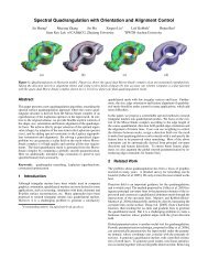
Figure 3: From left to right: Original horse model (49000 vertices), ellipsoid approximations consisting of 100 and 400 ellipsoids respectively<br />
(corresponding to 3600 and 14400 bytes).<br />
4. RESULTS<br />
Figure 3 depicts a typical ellipsoid decomposition of an object necessary<br />
as a preprocessing step for the actual transmission. We randomly<br />
selected 2500 of the original model’s 49000 vertices and applied<br />
the ellipsoid growing algorithm to them. Then we computed<br />
a suitable subset E ′ as described in Section 2.1. The complete<br />
preprocessing step took about half an hour.<br />
Figure 1 shows a typical reconstruction sequence as described<br />
in Section 2.2. The base geometry is represented by a 300 ellipsoid<br />
approximation (10800 bytes), the detail is divided into 6 chunks<br />
consisting of 5000 vertices (60000 bytes) each. The overhead for<br />
repeatedly transmitting the base geometry is only about 15 percent.<br />
An alternative approach would be to approximate the base<br />
geometry by a decimated mesh instead of a collection of ellipsoids<br />
[17]. However, in this case the correct transmission of the<br />
whole base mesh would be critical while in our case the size of the<br />
critical blocks is only the size of the channel packets.<br />
It turned out that the sample vertices can be re-inserted into the<br />
reconstruction in practically any order. In all our experiments the<br />
scheme has proven to be sufficiently robust even if more than half<br />
of the vertex data gets lost. This even allows us to refine a mesh<br />
only locally in regions of interest and deliberately discard vertices<br />
that are not relevant from the current viewpoint.<br />
5. ACKNOWLEDGEMENT<br />
This work was supported by the Deutsche Forschungsgemeinschaft<br />
under grant KO2064/1-1, “Distributed Processing and Delivery<br />
of Digital Documents”.<br />
6. REFERENCES<br />
[1] S. E. Chen, “QuickTime VR — An image-based approach to<br />
virtual environment navigation,” in SIGGRAPH 95 Proceedings,<br />
1995, pp. 29–38.<br />
[2] A. Ames, D. R. Nadeau, and J. L. Moreland, The VRML 2.0<br />
Sourcebook, John Wiley & Sons Inc, 1996.<br />
[3] R. Koenen, “Overview of the MPEG4 standard,” in<br />
http://mpeg.telecomitalialab.com/standards/mpeg-4/mpeg-<br />
4.htm, 2001.<br />
[4] M. Deering, “Geometric compression,” in SIGGRAPH 95<br />
Proceedings, 1995, pp. 13–20.<br />
[5] C. Touma and C. Gotsman, “Triangle mesh compression,” in<br />
Proceedings of Graphics Interface, 1998, pp. 26–34.<br />
[6] J. Rossignac, “Edgebreaker: Connectivity compression for<br />
triangle meshes,” IEEE Transactions on Visualization and<br />
Computer Graphics, vol. 5, no. 1, pp. 47–61, 1999.<br />
[7] H. Hoppe, “Progressive meshes,” in SIGGRAPH 96 Proceedings,<br />
1996, pp. 99–108.<br />
[8] P. Alliez and M. Desbrun, “Progressive encoding for lossless<br />
transmission of 3D meshes,” in SIGGRAPH 01 Proceedings,<br />
2001, pp. 195–202.<br />
[9] A. Khodakovsky, P. Schröder, and W. Sweldens, “Progressive<br />
geometry compression,” in SIGGRAPH 00 Proceedings,<br />
2000, pp. 271–278.<br />
[10] C. Hunt, TCP/IP network administration, O’Reilly, 1992.<br />
[11] S. Bischoff and L. Kobbelt, “Ellipsoid decomposition of 3D<br />
models,” to appear in 3D Data Processing, Transmission,<br />
Visualization Proceedings, 2002.<br />
[12] W. Boehm and H. Prautzsch, Geometric Concepts for Geometric<br />
Design, AK Peters, 1994.<br />
[13] W.E. Lorensen and H.E. Cline, “Marching Cubes: A high<br />
resolution 3D surface reconstruction algorithm,” in SIG-<br />
GRAPH 87 Proceedings, 1987, pp. 163–169.<br />
[14] G. Turk, “Re-tiling polygonal surfaces,” in SIGGRAPH 92<br />
Proceedings, 1992, pp. 55–64.<br />
[15] J. R. Shewchuk, Delaunay Refinement Mesh Generation,<br />
Ph.D. thesis, Carnegie Mellon University, Pittsburg, 1997.<br />
[16] H. Edelsbrunner, Geometry and Topology of Mesh Generation,<br />
Cambridge Univ. Press, England, 2001.<br />
[17] S. Bischoff and L. Kobbelt, “Towards robust broadcasting of<br />
geometry data,” to appear in Computers and Graphics.