7000 bar - Granzow
7000 bar - Granzow
7000 bar - Granzow

You also want an ePaper? Increase the reach of your titles
YUMPU automatically turns print PDFs into web optimized ePapers that Google loves.
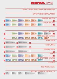
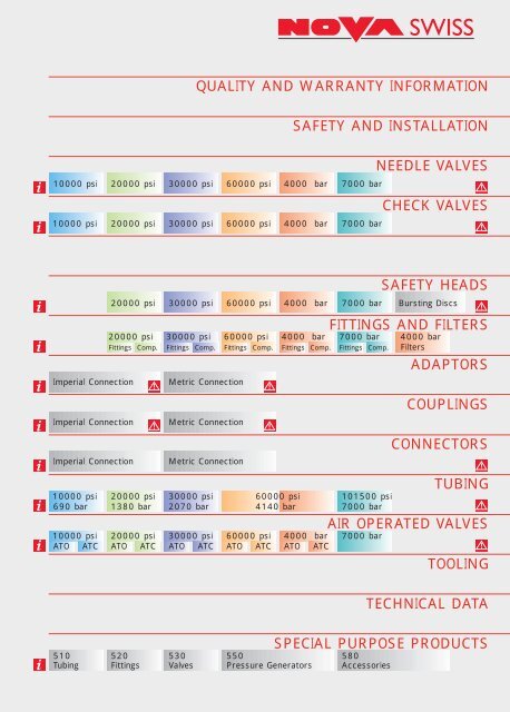
QUALITY AND WARRANTY INFORMATION<br />
SAFETY AND INSTALLATION<br />
10000 psi 20000 psi 30000 psi 60000 psi 4000 <strong>bar</strong> <strong>7000</strong> <strong>bar</strong><br />
10000 psi 20000 psi 30000 psi 60000 psi 4000 <strong>bar</strong> <strong>7000</strong> <strong>bar</strong><br />
NEEDLE VALVES<br />
CHECK VALVES<br />
Imperial Connection<br />
Imperial Connection<br />
Imperial Connection<br />
SAFETY HEADS<br />
20000 psi 30000 psi 60000 psi 4000 <strong>bar</strong> <strong>7000</strong> <strong>bar</strong> Bursting Discs<br />
FITTINGS AND FILTERS<br />
20000 psi 30000 psi 60000 psi 4000 <strong>bar</strong> <strong>7000</strong> <strong>bar</strong> 4000 <strong>bar</strong><br />
Fittings Comp. Fittings Comp. Fittings Comp. Fittings Comp. Fittings Comp. Filters<br />
Metric Connection<br />
Metric Connection<br />
Metric Connection<br />
10000 psi 20000 psi 30000 psi 60000 psi 101500 psi<br />
690 <strong>bar</strong> 1380 <strong>bar</strong> 2070 <strong>bar</strong> 4140 <strong>bar</strong> <strong>7000</strong> <strong>bar</strong><br />
10000 psi 20000 psi 30000 psi 60000 psi 4000 <strong>bar</strong> <strong>7000</strong> <strong>bar</strong><br />
ATO ATC ATO ATC ATO ATC ATO ATC ATO ATC<br />
ADAPTORS<br />
COUPLINGS<br />
CONNECTORS<br />
TUBING<br />
AIR OPERATED VALVES<br />
TOOLING<br />
TECHNICAL DATA<br />
SPECIAL PURPOSE PRODUCTS<br />
510 520 530 550 580<br />
Tubing Fittings Valves Pressure Generators Accessories
GENERAL SALES AND DELIVERY TERMS<br />
1. General Provisions<br />
The following terms exclusively are applicable to our offers, sales and<br />
deliveries. The placing of an order demonstrates the purchaser’s complete<br />
agreement with them. Divergent terms are only valid when they are<br />
specifically agreed upon and are confirmed by us in writing. The alteration of<br />
any individual term does not affect any other. The purchase terms of the<br />
buyer are not binding on us, even when we do not expressly oppose them.<br />
Rights and duties stemming from the sales agreement shall not be<br />
transferred to other persons without our express consent.<br />
2. Offers<br />
Offers shall be fixed for 60 days; thereafter, they are no longer binding, even<br />
when not specifically agreed upon.<br />
3. Orders<br />
Orders shall only be deemed to be accepted when they are<br />
confirmed in writing; oral acceptances are only valid insofar as they<br />
are confirmed in writing.<br />
4. Prices<br />
Our prices are not binding and are ex works, excluding packaging, postage,<br />
freight, insurance and customs duties as well as other shipping costs. If<br />
material and labour expenses, or other costs, undergo substantial change<br />
between the conclusion of the contract and delivery, we reserve the right to<br />
make price adjustments according to the sliding scale price formula of the<br />
Association of Swiss Machine Industrialists. Moreover, we reserve the right<br />
to increase prices for additional costs when subsequent delivery delays occur<br />
for which we are not responsible, or the size of deliveries, i.e. performances,<br />
agreed upon changes because the documents delivered by the purchaser do<br />
not correspond to the actual circumstances or are incomplete.<br />
We reserve the right to charge a minimum amount for small deliveries.<br />
5. Delivery<br />
For each order, the agreement on the term of delivery remains reserved.<br />
When making a shipment is impossible without our having been at fault, the<br />
delivery term is deemed to have been observed upon the announcement of<br />
shipping readiness. Partial deliveries may not be rejected by the buyer.<br />
Deliveries larger or smaller than the amount ordered, varying by up to 10<br />
percent of the ordered amount, are admissible. An obligation to comply with<br />
the delivery term agreed upon can only be assumed under the presumption<br />
of an uninterrupted manufacturing process. The consequences of force<br />
majeure, breakdown of the operation, official measures, lack of raw or<br />
auxiliary material, the failure of important supplies to be delivered to us or to<br />
our suppliers, or any other unforeseen circumstances entitle us to<br />
completely or partially suspend our delivery obligations. The nonobservance<br />
of confirmed delivery terms shall not justify claiming indemnification or<br />
withdrawal of orders. When obstacles to delivery have occurred which<br />
cannot be removed within a reasonable time, we reserve the right to cancel<br />
the agreement with corresponding notice to the purchaser. Indemnification<br />
claims due to non-performance or delayed performance are excluded. Upon<br />
leaving the factory, the full risk passes to the purchaser.<br />
6. Notices of Defects<br />
We shall only take into consideration complaints arising from deficient or<br />
incomplete delivery or performance when they are brought to our attention<br />
no later than 8 days after receipt of the delivery. We are liable for defects<br />
only within the framework of our warranty terms.<br />
7. Warranty<br />
We guarantee our good quality and careful manufacture of our products for<br />
a period of twelve months (calculated as of the shipping date) and repairs for<br />
a period of three months. This warranty exclusively covers material and<br />
manufacturing defects that appear during this period. Our warranty does not<br />
cover the natural wear and tear of parts as well as any damage, nor the<br />
consequences therefrom caused by improper handling, negligence,<br />
excessive usage or nonobservance of installation and service provisions. Our<br />
warranty expires immediately and fully when modifications or repairs are<br />
undertaken without our consent.<br />
7.1 Additional Functional Warranty for Engineering Orders<br />
This relates to the performance of a technical function of control,<br />
corresponding to the amended and confirmed duties record book. Such a<br />
functional warranty is granted only under the following conditions:<br />
1. A written order for the design of a control has been given.<br />
2. All technical information for the design as well as the desired functions<br />
of the control are stated in writing in a duties record book and conveyed<br />
to us.<br />
3. We have confirmed the technical functions according to the duties<br />
record book or informed the purchaser in writing of the necessary<br />
corrections and their causes prior to the realization of the control.<br />
If the functions agreed upon have not been achieved subsequent to the<br />
acceptance of the control, we shall remove the cause of the problem. If the<br />
cause of the problem is traced to a defective part, the warranty provisions<br />
for the delivery of product are applicable. When, however, the source of the<br />
problem can be traced to the purchaser, the purchaser must bear the cost<br />
of replacement and the investigation into the problem.<br />
If the problem can be traced to an incorrect interpretation of the control, we<br />
will also carry the assembly cost in addition to that for the diagnosis of the<br />
problem and it’s remedy, as long as the object in question is located in<br />
Switzerland or with the principal.<br />
If the problem can be traced to improper assembly, we are liable only if we<br />
have undertaken the assembly on behalf of the customer.<br />
The warranty term commences on the day of shipping readiness in our<br />
operation or, when the assembly is performed by us as well, on the day such<br />
assembly begins.<br />
8. Liability for Defects<br />
We are liable for defects only according to the legal provisions. Our liability<br />
for defects is limited exclusively to the obligation to replace defective parts,<br />
insofar as this is possible, without charge. The parts in question shall be<br />
sent back to us at our request and shall revert to our ownership. We do not<br />
grant indemnification of any kind, especially indemnification for loss of profit<br />
and consequential costs etc. The buyer also has no right to a reduction of<br />
the price, replacement, recission or revocation. For parts supplied by other<br />
companies delivered as elements of our products, only those obligations are<br />
accepted which our suppliers have entered into themselves. The return of<br />
defective products requires our prior approval.<br />
9. Retention of Title<br />
The delivered product remains our property until complete payment has<br />
been made therefor. The buyer may, however, further process the product<br />
within the framework of an orderly business operation and dispose thereof.<br />
By processing our product our ownership remains in effect. We acquire joint<br />
ownership in the new object in a proportion up to the according value of our<br />
original product.<br />
10. Payment<br />
Domestic deliveries are payable net without deduction within thirty days after<br />
the invoice issue date. For export transactions, the payment terms<br />
determined in the order confirmation are applicable. The purchase price is<br />
payable forthwith if the buyer is overdue with other payments owed to us or<br />
if we hear of the instability of the purchaser’s financial situation or<br />
bankruptcy, settlements, in or out of court, or protest of a bill of exchange.<br />
In these cases, we are entitled to make deliveries still outstanding only upon<br />
prepayment as well as to cancel the contract or to request indemnification<br />
due to nonperformance. Payment with bills of exchange requires a special<br />
agreement. Bills of exchange and checks are only accepted subject to having<br />
been honoured. Discount charges are to be paid according to the<br />
assignment. A payment is overdue even without previous reminders if the<br />
deadline of thirty days has been exceeded. Interest on overdue payments<br />
shall be paid at the usual bank interest rate.<br />
The buyer is not entitled to withhold payments in view of any counterclaims<br />
or to offset them against such counterclaims.<br />
11. Drawings, Samples, Tools and Forms<br />
Drawings, prototypes, samples, documents and drafts belonging to our<br />
company may not be made known to any third parties by the recipient and<br />
remain our property. Violation of this provision requires full indemnification.<br />
Drawings or documents sent with offers are to be immediately returned by<br />
the recipient when no order is made. Tools and forms remain our property<br />
even when pro rata costs are charged.<br />
12. Cancellation and Storage<br />
In the case of cancellation on the part of the purchaser, we are entitled to<br />
charge the purchaser for the costs incurred. Products that cannot be<br />
shipped after expiration of the delivery term at the request of the purchaser<br />
shall be charged by us and payment therefor shall be demanded after<br />
expiration of the payment term. Storage of the products at our facilities shall<br />
be at the risk of the purchaser.<br />
13. Place of performance and litigation<br />
The place of delivery and payment is Effretikon. The place of litigation for all<br />
litigation arising from the agreement is our business domicile. We<br />
furthermore reserve the right to file suit against the purchaser at his<br />
domicile.<br />
NOVA WERKE AG, CH-8307 Effretikon, Tel.: +41 (0) 52 354 16 37, Fax: +41 (0) 52 354 16 88, www.novaswiss.com<br />
QUALITY/WARRANTY 04/2002/E
SAFETY NOTES<br />
GENERAL<br />
The safety of the users of Nova High Pressure<br />
Components and Equipment is our prime concern.<br />
High pressure fluids can be dangerous when handled<br />
without care. Nova products enable the user to<br />
ensure maximum safety in system design and<br />
pressure handling.<br />
Read these safety notes and reference material<br />
carefully, as well as all notes, product data sheets and<br />
individual manuals, before using any Nova High<br />
Pressure Products.<br />
In addition to these safety notes the user should also<br />
be aware of:<br />
• state and/or company safety regulations, design<br />
codes and other applicable regulations, codes and<br />
standards.<br />
• these notes alone are not sufficient to be used as a<br />
guide to the design and manufacture of high<br />
pressure installations.<br />
• any “machine”, installation or equipment designed<br />
and built with Nova High Pressure Components is<br />
subject to CE-Regulations and country, state or local<br />
codes or regulations.<br />
• design responsibility rests with the system designer.<br />
• safety regulation for explosion proof zone.<br />
ACCIDENT PREVENTION REGULATIONS<br />
Users of Nova High Pressure Components should be<br />
familiar with the state, local and company accident<br />
prevention regulations, and operators should be<br />
trained in these periodically.<br />
EMERGENCY REGULATIONS<br />
In situations where testing of equipment or dangerous<br />
fluids are involved users should be aware of the<br />
potential dangers and take suitable precautions.<br />
Country, state or local codes or regulations may be<br />
relevant.<br />
PERSONNEL<br />
Nova High Pressure Products should only be used by<br />
experienced personnel trained in correct use. Users<br />
should be aware of the potential dangers of high<br />
pressure fluids.<br />
Operators should wear adequate ear and eye<br />
protection and all other suitable protective equipment,<br />
depending on the type of work undertaken.<br />
DESIGN CODES AND SAFETY MARGINS FOR<br />
NOVA HIGH PRESSURE COMPONENTS<br />
There are no specific international or national design<br />
codes for the Nova High Pressure Products shown<br />
within this catalogue. As such it is the manufacturers<br />
decision and responsibility to select appropriate<br />
calculation and design methods.<br />
Nova has been designing and building high pressure<br />
equipment for over 25 years, and our experience and<br />
record are evidence of the reliable design and<br />
calculation methods selected.<br />
CE-COMFORMITY<br />
All Nova High Pressure Components and Equipment<br />
are designed, built and marked according to CE-<br />
Regulation 98/37/EG.<br />
Every product has been subject to an extensive safety<br />
analysis.<br />
Each product is packed in sealed plastic bag where<br />
practically feasible with a users manual.<br />
Please contact your supplier should the users manual<br />
be wrong or be missing.<br />
LOCATION OF HIGH PRESSURE EQUIPMENT<br />
Users should satisfy themselves that the location of<br />
high pressure products does not lead to potentially<br />
dangerous situations arising. Particular care should be<br />
taken when pressure testing equipment, pressure<br />
vents should be directed away from test personnel and<br />
plugged or flanged ports adequately rated and<br />
correctly made up. Protective screens or walls are<br />
recommended where large volumes of fluid under<br />
pressure are involved or in situations where the<br />
behaviour of the equipment under test is<br />
unpredictable.<br />
ENERGY POTENTIAL<br />
All fluids under pressure contain energy i.e. they<br />
expand when the pressure is released. Liquids may<br />
contain air or other dissolved gases. Pure gases<br />
require far more energy to compress them to the<br />
desired pressure and are therefore considerably<br />
more dangerous than liquids when allowed to expand<br />
freely.<br />
Liquids however can be dangerous as a result of their<br />
density. If allowed to escape under pressure a jet<br />
results which is able to cut materials such as steel<br />
and concrete.<br />
No matter what the fluid under pressure the user<br />
should ensure that fluid is not allowed to escape in an<br />
uncontrolled manner.<br />
BUILDING AND FIRE REGULATIONS<br />
For permanent test or experimental installations,<br />
users should make themselves aware of country,<br />
state and local building regulations.<br />
NOVA WERKE AG, CH-8307 Effretikon, Tel.: +41 (0) 52 354 16 37, Fax: +41 (0) 52 354 16 88, www.novaswiss.com<br />
SAFETY NOTES 04/2002/E
PROPER USE<br />
It is essential that Nova High Pressure Products are<br />
used properly.<br />
PRESSURE<br />
Never use Nova High Pressure Products above their<br />
design pressure. The component with the lowest<br />
design pressure in a system determines the maximum<br />
pressure allowable for the entire system.<br />
The maximum allowable working pressure (MAWP) is<br />
marked on each product.<br />
When controlling fluctuating or varying pressures,<br />
always use equipment or components designed to the<br />
highest pressure peak expected in your system (see<br />
Dynamics).<br />
Ensure that pressure in a system is indicated at all<br />
points within a system that can be isolated.<br />
FLUID<br />
Always be aware of the nature, attributes and<br />
dangers of the working fluid and when ordering Nova<br />
High Pressure Products, always specify the working<br />
fluid to be used!<br />
When H2 (Hydrogen) or O2 (Oxygen) is specified for use<br />
with Nova High Pressure Products, our assembly<br />
department will use a special cleaning/degreasing<br />
process. Special care must be taken that these<br />
products, and any other products used in the same<br />
system, are not contaminated with grease, lubricant<br />
or any other product that will react or oxidise with H2<br />
or O2.<br />
Special care must be taken that any voluntary or<br />
accidental (bursting disc, relief valve or control valve)<br />
venting of these fluids will not cause fires, explosions<br />
or other damage.<br />
CORROSION<br />
A process fluid can adversely affect the integrity of<br />
pressure containing products in two ways. It can<br />
result in bulk corrosion or erosion of the internal<br />
surfaces and secondly, it can change the properties of<br />
the internal surfaces of the material which may lead<br />
to unpredictable and premature failure.<br />
Operating at high pressures can enhance the rate of<br />
corrosion, particularly when elevated temperatures<br />
are involved.<br />
Hydrogen Sulphide and Pure Hydrogen have a<br />
particularly serious potential impact on Stainless Steel<br />
in certain hardness conditions.<br />
The user is responsible for identifying the potential for<br />
corrosion in the system and taking adequate<br />
precautions to mitigate its affect.<br />
TEMPERATURE<br />
Nova High Pressure Product maximum allowable<br />
pressure ratings are at room temperature.<br />
Should you wish to use the equipment at other than<br />
room temperature, either higher or lower,<br />
temperature usage charts and information is<br />
included in the catalogue.<br />
The physical properties of the product materials,<br />
sealing materials and gaskets are affected<br />
substantially by temperature.<br />
Temperature indication should be installed in<br />
systems operating at reduced or elevated<br />
temperatures.<br />
DYNAMICS<br />
Where fluctuating pressures are involved, such as<br />
on the outlet from a reciprocating pump, care should<br />
be taken to ensure that pressure peaks do not<br />
exceed the maximum pressure ratings for high<br />
pressure products.<br />
Pressure ratings i.e. the maximum allowable working<br />
pressure relates to static or near static applications.<br />
Fluctuating pressures, i.e. dynamic fluids will,<br />
depending on rate and speed of the cycles, greatly<br />
affect the life of high pressure products. Generally,<br />
where high cyclic rates are to be expected,<br />
components and equipment with a considerably<br />
higher pressure rating than the system pressure<br />
should be used. Please consult your agent or the<br />
factory for enhancing measures such as autofrettage<br />
or electro-polishing.<br />
CONNECTIONS<br />
High and medium pressure coned and threaded<br />
connections are specifically designed to safely<br />
contain fluids under high pressures in critical<br />
applications.<br />
All connection types should never be interfered with<br />
when pressure is held within the system.<br />
Weep holes should never be obstructed or welded<br />
shut.<br />
When connecting Nova Swiss High Pressure<br />
Equipment/Components to any other non-Nova Swiss<br />
Equipment, always ensure that there is a weep hole<br />
in that part.<br />
NOVA WERKE AG, CH-8307 Effretikon, Tel.: +41 (0) 52 354 16 37, Fax: +41 (0) 52 354 16 88, www.novaswiss.com<br />
SAFETY NOTES 04/2002/E
NEEDLE<br />
VALVES<br />
VALVES, FITTINGS AND TUBING FOR CRITICAL SERVICE
THE NEW APPROACH FROM NOVA SWISS<br />
Simplicity is the key.<br />
• The New Nova range combines 25 years<br />
experience of supplying the highest quality valve<br />
products that have been subjected to rigorous<br />
testing combined with elegant simplicity in design.<br />
• Nova Swiss have produced a range of products<br />
that better meet the needs of critical service<br />
applications, where safety reliability and leak tight<br />
sealing are paramount.<br />
• With modern sealing technology and less parts<br />
than similar products, the valves offer maximum<br />
ease of use and simple maintenance.<br />
• All needle valves are supplied with glands and<br />
collars as required by the products, except<br />
BSPP and NPT connections.<br />
• Innovations include the decision to produce all<br />
needle valves rated upto and including<br />
30000 psi with pressure bearing parts in<br />
NACE MR-01-75 approved material. This is<br />
of particular benefit to the oil and gas<br />
exploration and production industries, where<br />
significant cost benefits will result.<br />
• Considerable effort has also been put into the<br />
thorough testing of all products specifically<br />
cyclic service and fatigue pressure testing<br />
which we believe is unique to Nova Swiss.<br />
• All valves are bidirectional which simplifies<br />
system design.<br />
• Everything is aimed at better serving<br />
the needs of our customers.<br />
ERGONOMIC HANDLE DESIGN –<br />
POSITIVE GRIP<br />
Ease of operation<br />
MOUNTING SCREWS INCLUDED<br />
Ease of installation<br />
2 PIECE NON ROTATING STEM<br />
Avoids seat/stem galling to provide<br />
optimum reliability<br />
VENT HOLES ON ALL CONED AND<br />
THREADED CONNECTIONS/SEAL AREAS<br />
To provide a safe discharge of pressure in the<br />
event of an inadvertant leak<br />
60 0 STEM TIP AND RADIUSSED SEAT<br />
Optimum sealing characteristics and<br />
dependable, reliable and repeatable sealing<br />
with gases and liquids<br />
CONED AND THREADED CONNECTIONS<br />
For Reliability & Safety,<br />
Repeatable sealing make/break<br />
SEAL BELOW STEM THREADS<br />
Safety - leakage vented<br />
EACH BATCH TESTED PRIOR<br />
TO DESPATCH<br />
To ensure your product<br />
doesn’t let you down<br />
ALTERNATIVE<br />
MATERIALS AVAILABLE<br />
CUSTOM DESIGN<br />
SERVICE TO MATCH<br />
YOUR NEEDS<br />
BODY & PRESSURE BEARING<br />
PARTS TO NACE MR-01-75 AS<br />
STANDARD UP TO 30,000 psi<br />
Easier to specify<br />
Less inventory<br />
Peace of mind<br />
Interchangeability<br />
TOTAL TRACEABILITY<br />
CERTIFICATE<br />
Upon request<br />
all pressure retaining parts<br />
fully traceable to better meet<br />
your quality control<br />
requirements<br />
TRACEABILITY CERTIFICATE<br />
As standard for body<br />
material certificate accredited<br />
to EN 1024 3.1.B. to meet<br />
your quality control and<br />
certification requirements<br />
NOVA WERKE AG, CH-8307 Effretikon, Tel.: +41 (0) 52 354 16 37, Fax: +41 (0) 52 354 16 88, www.novaswiss.com<br />
NEEDLE VALVES 04/2002/E
E LEVATED T EMPERATURE U SAGE<br />
The following graph is for use with the Nova range of 316 stainless steel needle valves. The thick line<br />
depicts the reduction in yield stress of the 316 and the corresponding reduction in valve rated pressure<br />
(some valves may be operated in the area above the line – consult agent or factory for specific cases).<br />
The allowable operating temperature range is governed by the stem packing material and this range is<br />
shown coloured on the graph.<br />
The graph should be used for reference only as other considerations such as fatigue, creep, corrosion<br />
etc can affect performance at elevated temperatures. Please consult agent or factory for unusual<br />
operating conditions.<br />
S T ANDARD M A TERIALS OF C ONSTRUCTION<br />
Valve body (10, 20, 30,000 psi)<br />
AISI 316 L/DIN 1.4404 to NACE MR-01-75<br />
Valve body (60,000 psi/4000 <strong>bar</strong>/<strong>7000</strong> <strong>bar</strong>) AISI 316 L/DIN 1.4404<br />
Upper stem AISI 416 L/DIN 1.4005<br />
Bonnet Aluminium bronze NES 833<br />
Lower stem 17-4 PH/DIN 1.4542<br />
Stem guide 17-4 PH/DIN 1.4542<br />
Stem washer 17-4 PH/DIN 1.4542<br />
Packing<br />
Glass filled PTFE<br />
Screws<br />
A2<br />
Glands<br />
AISI 316 L/DIN 1.4404 (to NACE MR-01-75)*<br />
Collars<br />
AISI 316 L/DIN 1.4404 (to NACE MR-01-75)*<br />
*(MPCT and HPCT connection components)<br />
NOVA WERKE AG, CH-8307 Effretikon, Tel.: +41 (0) 52 354 16 37, Fax: +41 (0) 52 354 16 88, www.novaswiss.com<br />
NEEDLE VALVES 04/2002/E
10000 psi<br />
NEEDLE VALVES<br />
BSPP & NPT<br />
CONNECTIONS<br />
BSPP CONNECTIONS<br />
Catalogue Port Orifice<br />
Number Size Dia A B C D E F G H J T<br />
STRAIGHT<br />
NV1-10-4B 1/4 0.18 2.95 5.24 2.36 1.81 1.38 1.38 0.88 0.39 2.00 1.13<br />
6.4 4.5 75 133 60 46 35 35 22.2 10 50.8 28.6<br />
NV1-10-6B 3/8 0.26 2.95 5.47 2.60 1.97 1.46 1.38 0.88 0.39 2.00 1.13<br />
9.5 6.5 75 139 66 50 37 35 22.2 10 50.8 28.6<br />
NV1-10-8B 1/2 0.30 4.06 5.71 2.83 1.97 1.42 1.38 0.88 0.39 2.50 1.50<br />
12.7 7.5 103 145 72 50 36 35 22.2 10 63.5 38.1<br />
ANGLE<br />
NV2-10-4B 1/4 0.18 2.95 5.24 2.36 1.38 1.38 0.88 0.39 2.00 1.13<br />
6.4 4.5 75 133 60 35 35 22.2 10 50.8 28.6<br />
NV2-10-6B 3/8 0.26 2.95 5.47 2.60 1.46 1.38 0.88 0.39 2.00 1.13<br />
9.5 6.5 75 139 66 37 35 22.2 10 50.8 28.6<br />
NV2-10-8B 1/2 0.30 4.06 5.71 2.83 1.42 1.38 0.88 0.39 2.50 1.50<br />
12.7 7.5 103 145 72 36 35 22.2 10 63.5 38.1<br />
TEE<br />
NV3-10-4B 1/4 0.18 2.95 5.24 2.36 1.38 1.38 0.88 0.39 2.00 1.13<br />
6.4 4.5 75 133 60 35 35 22.2 10 50.8 28.6<br />
NV3-10-6B 3/8 0.26 2.95 5.47 2.60 1.46 1.38 0.88 0.39 2.00 1.13<br />
9.5 6.5 75 139 66 37 35 22.2 10 50.8 28.6<br />
NV3-10-8B 1/2 0.30 4.06 5.71 2.83 1.42 1.38 0.88 0.39 2.50 1.50<br />
12.7 7.5 103 145 72 36 35 22.2 10 63.5 38.1<br />
NPT CONNECTIONS<br />
Catalogue Port Orifice<br />
Number Size Dia A B C D E F G H J T<br />
STRAIGHT<br />
NV1-10-4N 1/4 0.18 2.95 5.24 2.36 1.81 1.38 1.38 0.88 0.39 2.00 1.13<br />
6.4 4.5 75 133 60 46 35 35 22.2 10 50.8 28.6<br />
NV1-10-6N 3/8 0.26 2.95 5.47 2.60 1.97 1.46 1.38 0.88 0.39 2.00 1.13<br />
9.5 6.5 75 139 66 50 37 35 22.2 10 50.8 28.6<br />
NV1-10-8N 1/2 0.30 4.06 5.71 2.83 1.97 1.42 1.38 0.88 0.39 2.50 1.13<br />
12.7 7.5 103 145 72 50 36 35 22.2 10 63.5 28.6<br />
ANGLE<br />
NV2-10-4N 1/4 0.18 2.95 5.24 2.36 1.38 1.38 0.88 0.39 2.00 1.13<br />
6.4 4.5 75 133 60 35 35 22.2 10 50.8 28.6<br />
NV2-10-6N 3/8 0.26 2.95 5.47 2.60 1.46 1.38 0.88 0.39 2.00 1.13<br />
9.5 6.5 75 139 66 37 35 22.2 10 50.8 28.6<br />
NV2-10-8N 1/2 0.30 4.06 5.71 2.83 1.42 1.38 0.88 0.39 2.50 1.13<br />
12.7 7.5 103 145 72 36 35 22.2 10 63.5 28.6<br />
TEE<br />
NV3-10-4N 1/4 0.18 2.95 5.24 2.36 1.38 1.38 0.88 0.39 2.00 1.13<br />
6.4 4.5 75 133 60 35 35 22.2 10 50.8 28.6<br />
NV3-10-6N 3/8 0.26 2.95 5.47 2.60 1.46 1.38 0.88 0.39 2.00 1.13<br />
9.5 6.5 75 139 66 37 35 22.2 10 50.8 28.6<br />
NV3-10-8N 1/2 0.30 4.06 5.71 2.83 1.42 1.38 0.88 0.39 2.50 1.13<br />
12.7 7.5 103 145 72 36 35 22.2 10 63.5 28.6<br />
NOTES<br />
1 Refer to Needle Valve graph for elevated temperature usage.<br />
Environmental temperature range -50 O C to +65 O C.<br />
2 All valves in Stainless Steel Grade 316 suitable for sour gas service.<br />
3 All valves are bi-directional.<br />
4 Top mounting screw size = M5 x 0.8.<br />
Side mounting holes = Ø6 (0.24”).<br />
5 Due to our policy of continuous development we reserve the right to modify products<br />
and specifications without notice.<br />
NOVA WERKE AG, CH-8307 Effretikon, Tel.: +41 (0) 52 354 16 37, Fax: +41 (0) 52 354 16 88, www.novaswiss.com<br />
NEEDLE VALVES 04/2002/E
20000 psi<br />
NEEDLE VALVES<br />
MEDIUM PRESSURE<br />
C+T CONNECTIONS<br />
MP C+T CONNECTIONS<br />
Catalogue Tube Orifice<br />
Number O/D Dia A B C D E F G H J T<br />
STRAIGHT<br />
NV1-20-4M 1/4 0.11 2.95 5.24 2.36 1.73 1.38 1.38 0.88 0.39 2.00 1.13<br />
6.4 2.8 75 133 60 44 35 35 22.2 10 50.8 28.6<br />
NV1-20-6M 3/8 0.20 2.95 5.47 2.60 1.81 1.38 1.38 0.88 0.39 2.00 1.13<br />
9.5 5.0 75 139 66 46 35 35 22.2 10 50.8 28.6<br />
NV1-20-9M 9/16 0.30 4.06 5.71 2.83 1.97 1.42 1.38 0.88 0.39 2.50 1.13<br />
14.3 7.5 103 145 72 50 36 35 22.2 10 63.5 28.6<br />
NV1-20-12M 3/4 0.44 9.84 6.97 3.74 2.87 1.93 2.20 1.25 0.81 3.00 1.38<br />
19.1 11.1 250 177 95 73 49 56 31.8 20.5 76.2 34.9<br />
NV1-20-16M 1 0.56 9.84 7.36 4.13 2.87 1.93 2.20 1.25 0.81 4.13 1.63<br />
25.4 14.3 250 187 105 73 49 56 31.8 20.5 105 41.3<br />
ANGLE<br />
NV2-20-4M 1/4 0.11 2.95 5.24 2.36 1.38 1.38 0.88 0.39 2.00 1.13<br />
6.4 2.8 75 133 60 35 35 22.2 10 50.8 28.6<br />
NV2-20-6M 3/8 0.20 2.95 5.47 2.60 1.38 1.38 0.88 0.39 2.00 1.13<br />
9.5 5.0 75 139 66 35 35 22.2 10 50.8 28.6<br />
NV2-20-9M 9/16 0.30 4.06 5.71 2.83 1.42 1.38 0.88 0.39 2.50 1.13<br />
14.3 7.5 103 145 72 36 35 22.2 10 63.5 28.6<br />
NV2-20-12M 3/4 0.44 9.84 6.97 3.74 1.93 2.20 1.25 0.81 3.00 1.38<br />
19.1 11.1 250 177 95 49 56 31.8 20.5 76.2 34.9<br />
NV2-20-16M 1 0.56 9.84 7.36 4.13 1.93 2.20 1.25 0.81 4.13 1.63<br />
25.4 14.3 250 187 105 49 56 31.8 20.5 105 41.3<br />
TEE<br />
NV3-20-4M 1/4 0.11 2.95 5.24 2.36 1.38 1.38 0.88 0.39 2.00 1.13<br />
6.4 2.8 75 133 60 35 35 22.2 10 50.8 28.6<br />
NV3-20-6M 3/8 0.20 2.95 5.47 2.60 1.38 1.38 0.88 0.39 2.00 1.13<br />
9.5 5.0 75 139 66 35 35 22.2 10 50.8 28.6<br />
NV3-20-9M 9/16 0.30 4.06 5.71 2.83 1.42 1.38 0.88 0.39 2.50 1.13<br />
14.3 7.5 103 145 72 36 35 22.2 10 63.5 28.6<br />
NV3-20-12M 3/4 0.44 9.84 6.97 3.74 1.93 2.20 1.25 0.81 3.00 1.38<br />
19.1 11.1 250 177 95 49 56 31.8 20.5 76.2 34.9<br />
NV3-20-16M 1 0.56 9.84 7.36 4.13 1.93 2.20 1.25 0.81 4.13 1.63<br />
25.4 14.3 250 187 105 49 56 31.8 20.5 105 41.3<br />
REPLACEABLE SEAT<br />
NV5-20-4M 1/4 0.11 2.95 5.24 2.36 1.38 1.38 0.88 0.39 2.00 1.13<br />
6.4 2.8 75 133 60 35 35 22.2 10 50.8 28.6<br />
NV5-20-6M 3/8 0.20 2.95 5.47 2.60 1.36 1.38 0.88 0.39 2.00 1.13<br />
9.5 5.0 75 139 66 34.5 35 22.2 10 50.8 28.6<br />
NV5-20-9M 9/16 0.30 4.06 5.71 2.83 1.40 1.38 0.88 0.39 2.50 1.13<br />
14.3 7.5 103 145 72 35.5 35 22.2 10 63.5 28.6<br />
NV5-20-12M 3/4 0.44 9.84 6.97 3.74 1.93 2.20 1.25 0.81 3.00 1.38<br />
19.1 11.1 250 177 95 49 56 31.8 20.5 76.2 34.9<br />
NV5-20-16M 1 0.56 9.84 7.36 4.13 1.93 2.20 1.25 0.81 4.13 1.63<br />
25.4 14.3 250 187 105 49 56 31.8 20.5 105 41.3<br />
NOTES<br />
1 Refer to Needle Valve graph for elevated temperature usage.<br />
Environmental temperature range -50 O C to +65 O C.<br />
2 All valves in Stainless Steel Grade 316 suitable for sour gas service.<br />
3 All valves are bi-directional.<br />
4 Top mounting screw size = M5 x 0.8 (1/4, 3/8, 9/16 V/Vs), M8 x 1.25 (3/4, 1 V/Vs)<br />
Side mounting holes = Ø6 (0.24”) (1/4, 3/8, 9/16 V/Vs), Ø10.5 (0.41”) (3/4, 1 V/Vs)<br />
5 All coned and threaded connection valves supplied with glands and collars.<br />
6 Due to our policy of continuous development we reserve the right to modify products<br />
and specifications without notice.<br />
NOVA WERKE AG, CH-8307 Effretikon, Tel.: +41 (0) 52 354 16 37, Fax: +41 (0) 52 354 16 88, www.novaswiss.com<br />
NEEDLE VALVES 04/2002/E
30000 psi<br />
NEEDLE VALVES<br />
HIGH PRESSURE<br />
C+T CONNECTIONS<br />
HP C+T CONNECTIONS<br />
Catalogue Tube Orifice<br />
Number O/D Dia A B C D E F G H J T<br />
STRAIGHT<br />
NV1-30-4H 1/4 0.09 2.95 5.24 2.36 1.73 1.38 1.38 0.88 0.39 2.00 1.13<br />
6.4 2.4 75 133 60 44 35 35 22.2 10 50.8 28.6<br />
NV1-30-6H 3/8 0.12 2.95 5.47 2.60 1.77 1.38 1.38 0.88 0.39 2.00 1.13<br />
9.5 3.0 75 139 66 45 35 35 22.2 10 50.8 28.6<br />
NV1-30-9H 9/16 0.12 4.06 5.71 2.83 1.81 1.38 1.38 0.88 0.39 2.50 1.50<br />
14.3 3.0 103 145 72 46 35 35 22.2 10 63.5 38.1<br />
ANGLE<br />
NV2-30-4H 1/4 0.09 2.95 5.24 2.36 1.38 1.38 0.88 0.39 2.00 1.13<br />
6.4 2.4 75 133 60 35 35 22.2 10 50.8 28.6<br />
NV2-30-6H 3/8 0.12 2.95 5.47 2.60 1.38 1.38 0.88 0.39 2.00 1.13<br />
9.5 3.0 75 139 66 35 35 22.2 10 50.8 28.6<br />
NV2-30-9H 9/16 0.12 4.06 5.71 2.83 1.38 1.38 0.88 0.39 2.50 1.50<br />
14.3 3.0 103 145 72 35 35 22.2 10 63.5 38.1<br />
TEE<br />
NV3-30-4H 1/4 0.09 2.95 5.24 2.36 1.38 1.38 0.88 0.39 2.00 1.13<br />
6.4 2.4 75 133 60 35 35 22.2 10 50.8 28.6<br />
NV3-30-6H 3/8 0.12 2.95 5.47 2.60 1.38 1.38 0.88 0.39 2.00 1.13<br />
9.5 3.0 75 139 66 35 35 22.2 10 50.8 28.6<br />
NV3-30-9H 9/16 0.12 4.06 5.71 2.83 1.38 1.38 0.88 0.39 2.50 1.50<br />
14.3 3.0 103 145 72 35 35 22.2 10 63.5 38.1<br />
REPLACEABLE SEAT<br />
NV5-30-4H 1/4 0.09 2.95 5.24 2.36 1.38 1.38 0.88 0.39 2.00 1.13<br />
6.4 2.4 75 133 60 35 35 22.2 10 50.8 28.6<br />
NV5-30-6H 3/8 0.12 2.95 5.47 2.60 1.30 1.38 0.88 0.39 2.00 1.13<br />
9.5 3.0 75 139 66 33 35 22.2 10 50.8 28.6<br />
NV5-30-9H 9/16 0.12 4.06 5.71 2.83 1.34 1.38 0.88 0.39 2.50 1.50<br />
14.3 3.0 103 145 72 34 35 22.2 10 63.5 38.1<br />
NOTES<br />
1 Refer to Needle Valve graph for elevated temperature usage.<br />
Environmental temperature range -50 O C to +65 O C.<br />
2 All valves in Stainless Steel Grade 316 suitable for sour gas service.<br />
3 All valves are bi-directional.<br />
4 Top mounting screw size = M5 x 0.8.<br />
Side mounting holes = Ø6 (0.24”).<br />
5 All coned and threaded connection valves supplied with glands and collars.<br />
6 Due to our policy of continuous development we reserve the right to modify products<br />
and specifications without notice.<br />
NOVA WERKE AG, CH-8307 Effretikon, Tel.: +41 (0) 52 354 16 37, Fax: +41 (0) 52 354 16 88, www.novaswiss.com<br />
NEEDLE VALVES 04/2002/E
60000 psi<br />
NEEDLE VALVES<br />
HIGH PRESSURE<br />
C+T CONNECTIONS<br />
HP C+T CONNECTIONS<br />
Catalogue Tube Orifice<br />
Number O/D Dia A B C D E F G H J T<br />
STRAIGHT<br />
NV1-60-4H 1/4 0.09 4.06 5.24 2.36 1.73 1.38 1.38 0.88 0.39 2.00 1.13<br />
6.4 2.4 103 133 60 44 35 35 22.2 10 50.8 28.6<br />
NV1-60-6H 3/8 0.12 4.06 5.47 2.60 1.77 1.38 1.38 0.88 0.39 2.00 1.13<br />
9.5 3.0 103 139 66 45 35 35 22.2 10 50.8 28.6<br />
NV1-60-9H 9/16 0.12 4.06 5.71 2.83 1.81 1.38 1.38 0.88 0.39 2.50 1.50<br />
14.3 3.0 103 145 72 46 35 35 22.2 10 63.5 38.1<br />
ANGLE<br />
NV2-60-4H 1/4 0.09 4.06 5.24 2.36 1.38 1.38 0.88 0.39 2.00 1.13<br />
6.4 2.4 103 133 60 35 35 22.2 10 50.8 28.6<br />
NV2-60-6H 3/8 0.12 4.06 5.47 2.60 1.38 1.38 0.88 0.39 2.00 1.13<br />
9.5 3.0 103 139 66 35 35 22.2 10 50.8 28.6<br />
NV2-60-9H 9/16 0.12 4.06 5.71 2.83 1.38 1.38 0.88 0.39 2.50 1.50<br />
14.3 3.0 103 145 72 35 35 22.2 10 63.5 38.1<br />
TEE<br />
NV3-60-4H 1/4 0.09 4.06 5.24 2.36 1.38 1.38 0.88 0.39 2.00 1.13<br />
6.4 2.4 103 133 60 35 35 22.2 10 50.8 28.6<br />
NV3-60-6H 3/8 0.12 4.06 5.47 2.60 1.38 1.38 0.88 0.39 2.00 1.13<br />
9.5 3.0 103 139 66 35 35 22.2 10 50.8 28.6<br />
NV3-60-9H 9/16 0.12 4.06 5.71 2.83 1.38 1.38 0.88 0.39 2.50 1.50<br />
14.3 3.0 103 145 72 35 35 22.2 10 63.5 38.1<br />
REPLACEABLE SEAT<br />
NV5-60-4H 1/4 0.09 4.06 5.24 2.36 1.38 1.38 0.88 0.39 2.00 1.13<br />
6.4 2.4 103 133 60 35 35 22.2 10 50.8 28.6<br />
NV5-60-6H 3/8 0.12 4.06 5.47 2.60 1.30 1.38 0.88 0.39 2.00 1.13<br />
9.5 3.0 103 139 66 33 35 22.2 10 50.8 28.6<br />
NV5-60-9H 9/16 0.12 4.06 5.71 2.83 1.34 1.38 0.88 0.39 2.50 1.50<br />
14.3 3.0 103 145 72 34 35 22.2 10 63.5 38.1<br />
NOTES<br />
1 Refer to Needle Valve graph for elevated temperature usage.<br />
Environmental temperature range -50 O C to +65 O C.<br />
2 All valves in Stainless Steel Grade 316.<br />
3 All valves are bi-directional.<br />
4 Top mounting screw size = M5 x 0.8.<br />
Side mounting holes = Ø6 (0.24”).<br />
5 All coned and threaded connection valves supplied with glands and collars.<br />
6 Due to our policy of continuous development we reserve the right to modify products<br />
and specifications without notice.<br />
NOVA WERKE AG, CH-8307 Effretikon, Tel.: +41 (0) 52 354 16 37, Fax: +41 (0) 52 354 16 88, www.novaswiss.com<br />
NEEDLE VALVES 04/2002/E
4000 <strong>bar</strong><br />
NEEDLE VALVES<br />
HIGH PRESSURE<br />
METRIC<br />
CONNECTIONS<br />
E<br />
E CONNECTIONS<br />
Catalogue Tube Orifice<br />
Number O/D Dia A B C D E F G H J T<br />
STRAIGHT<br />
NV1-40-4E 1/4 0.09 4.06 5.24 2.36 1.73 1.38 1.38 0.88 0.39 2.00 1.13<br />
6.4 2.4 103 133 60 44 35 35 22.2 10 50.8 28.6<br />
NV1-40-6E 3/8 0.12 4.06 5.47 2.60 1.77 1.38 1.38 0.88 0.39 2.00 1.13<br />
9.5 3.0 103 139 66 45 35 35 22.2 10 50.8 28.6<br />
NV1-40-9E 9/16 0.12 4.06 5.71 2.83 1.81 1.38 1.38 0.88 0.39 2.50 1.50<br />
14.3 3.0 103 145 72 46 35 35 22.2 10 63.5 38.1<br />
ANGLE<br />
NV2-40-4E 1/4 0.09 4.06 5.24 2.36 1.38 1.38 0.88 0.39 2.00 1.13<br />
6.4 2.4 103 133 60 35 35 22.2 10 50.8 28.6<br />
NV2-40-6E 3/8 0.12 4.06 5.47 2.60 1.38 1.38 0.88 0.39 2.00 1.13<br />
9.5 3.0 103 139 66 35 35 22.2 10 50.8 28.6<br />
NV2-40-9E 9/16 0.12 4.06 5.71 2.83 1.38 1.38 0.88 0.39 2.50 1.50<br />
14.3 3.0 103 145 72 35 35 22.2 10 63.5 38.1<br />
TEE<br />
NV3-40-4E 1/4 0.09 4.06 5.24 2.36 1.38 1.38 0.88 0.39 2.00 1.13<br />
6.4 2.4 103 133 60 35 35 22.2 10 50.8 28.6<br />
NV3-40-6E 3/8 0.12 4.06 5.47 2.60 1.38 1.38 0.88 0.39 2.00 1.13<br />
9.5 3.0 103 139 66 35 35 22.2 10 50.8 28.6<br />
NV3-40-9E 9/16 0.12 4.06 5.71 2.83 1.38 1.38 0.88 0.39 2.50 1.50<br />
14.3 3.0 103 145 72 35 35 22.2 10 63.5 38.1<br />
REPLACEABLE SEAT<br />
NV5-40-4E 1/4 0.09 4.06 5.24 2.36 1.38 1.38 0.88 0.39 2.00 1.13<br />
6.4 2.4 103 133 60 35 35 22.2 10 50.8 28.6<br />
NV5-40-6E 3/8 0.12 4.06 5.47 2.60 1.30 1.38 0.88 0.39 2.00 1.13<br />
9.5 3.0 103 139 66 33 35 22.2 10 50.8 28.6<br />
NV5-40-9E 9/16 0.12 4.06 5.71 2.83 1.34 1.38 0.88 0.39 2.50 1.50<br />
14.3 3.0 103 145 72 34 35 22.2 10 63.5 38.1<br />
3-WAY/2-STEM MANIFOLD<br />
NV6-40-4E 1/4 0.09 4.06 6.97 4.09 2.05 1.38 1.38 0.88 0.39 2.00 1.13<br />
6.4 2.4 103 177 104 52 35 35 22.2 10 50.8 28.6<br />
NV6-40-6E 3/8 0.12 4.06 6.97 4.09 2.05 1.38 1.38 0.88 0.39 2.00 1.13<br />
9.5 3.0 103 177 104 52 35 35 22.2 10 50.8 28.6<br />
NOTES<br />
1 Refer to Needle Valve graph for elevated temperature usage.<br />
Environmental temperature range -50 O C to +65 O C.<br />
2 All valves in Stainless Steel Grade AISI 316L/DIN 1.4404.<br />
3 All valves are bi-directional.<br />
4 Top mounting screw size = M5 x 0.8.<br />
Side mounting holes = Ø6 (0.24”).<br />
5 All coned and threaded connection valves supplied with glands and collars.<br />
6 Due to our policy of continuous development we reserve the right to modify products<br />
and specifications without notice.<br />
NOVA WERKE AG, CH-8307 Effretikon, Tel.: +41 (0) 52 354 16 37, Fax: +41 (0) 52 354 16 88, www.novaswiss.com<br />
NEEDLE VALVES 04/2002/E
<strong>7000</strong> <strong>bar</strong><br />
NEEDLE VALVES<br />
HIGH PRESSURE<br />
METRIC<br />
CONNECTIONS<br />
E<br />
E CONNECTIONS<br />
Catalogue Tube Orifice<br />
Number O/D Dia A B C D E F G H J T<br />
STRAIGHT<br />
NV1-70-4E 1/4 0.06 4.06 5.59 2.76 2.09 1.73 1.38 1.06 0.39 2.00 1.13<br />
6.4 1.6 103 142 70 53 44 35 27 10 50.8 28.5<br />
REPLACEABLE SEAT<br />
NV5-70-4E 1/4 0.06 4.06 5.59 2.76 1.73 1.38 1.06 0.39 2.00 1.13<br />
6.4 1.6 103 142 70 44 35 27 10 50.8 28.5<br />
NOTES<br />
1 Refer to Needle Valve graph for elevated temperature usage.<br />
Environmental temperature range -50 O C to +65 O C.<br />
2 All valves in Stainless Steel Grade AISI 316L/DIN 1.4404.<br />
3 All valves are bi-directional.<br />
4 Side mounting holes = Ø6 (0.24”).<br />
5 All coned and threaded connection valves supplied with glands and collars.<br />
6 Due to our policy of continuous development we reserve the right to modify products<br />
and specifications without notice.<br />
NOVA WERKE AG, CH-8307 Effretikon, Tel.: +41 (0) 52 354 16 37, Fax: +41 (0) 52 354 16 88, www.novaswiss.com<br />
NEEDLE VALVES 04/2002/E
SAFETY NOTES<br />
As your safety is our prime concern and we want you to enjoy<br />
reliable service from our products we give the following<br />
advice on the safe use of Needle Valves.<br />
•High pressure fluids particularly gases are potentially<br />
hazardous and should always be treated with the greatest<br />
respect. Do not vent fluid without knowing where vent is<br />
directed<br />
•Always be aware of whether pressure is contained by a<br />
valve<br />
•Do not loosen connection components when system<br />
pressure is present<br />
•Ensure valves are open and that no system pressure is<br />
present and isolated prior to carrying out maintenance<br />
NEEDLE VALVE SELECTION<br />
Suitability of individual valves for chosen application is<br />
dependant on a number of parameters which should be<br />
given careful consideration prior to use. To assist our<br />
customers in selection we have compiled a list of selection<br />
criteria which takes account of many of the most important<br />
factors to consider. As all systems are different and user<br />
requirements vary greatly this information should not be<br />
considered comprehensive. Should you have any doubts as<br />
to the suitability of a chosen valve please contact the local<br />
agent or the factory directly. Either will be delighted to<br />
assist.<br />
PRESSURE<br />
System pressure should always be less than the maximum<br />
allowable working pressure for the valve. Where fluctuating<br />
pressures are involved such as on the outlet from a<br />
reciprocating pump, care should be taken to ensure that<br />
pressure peaks do not exceed this maximum.<br />
We recommend that where fluctuating pressure is<br />
occurring over long periods then the valve pressure rating<br />
should be considerably higher than the maximum nominal<br />
system working pressure. Please note that the operating<br />
life will be reduced.<br />
TEMPERATURE<br />
Valve maximum operating temperature is based on the<br />
working fluid temperature i.e. the temperature that the<br />
valve will see internally. Should you wish to operate valves in<br />
an environment outside the specified operating temperature<br />
range please consult the local agent or factory as the seals<br />
used within the valve stem assembly may need to be<br />
changed to a higher temperature tolerant grade.<br />
Valve pressure rating is based on temperature not<br />
exceeding the maximum allowable working value and is<br />
reduced should this temperature be exceeded. Working<br />
pressure versus operating temperature is shown graphically<br />
on the data page.<br />
In all cases where the intended operating temperature will<br />
or could even temporarily exceed the maximum limit, the<br />
user should consult the local agent or factory directly.<br />
SYSTEM FLUID<br />
There are two principal considerations, firstly the<br />
nature of the fluid and its compatibility with the<br />
materials of construction and secondly the level of<br />
cleanliness of the fluid.<br />
The customer should satisfy themselves that the materials<br />
of construction including stem seals are compatible with<br />
the working fluids with respect to corrosion and/or other<br />
chemical reaction.<br />
System fluid should be clean and in particular not contain<br />
any debris which is abrasive. Cleanliness levels of NAS<br />
1638 (National Aerospace Standard 1638) level 10 or<br />
better are optimum.<br />
CONNECTIONS<br />
Nova valves are supplied with a variety of connection<br />
options with pressure limitations for each design.<br />
These are the limitations:-<br />
BSPP - Parallel thread connection relies on an externally<br />
clamped seal to hold pressure. Threads are<br />
exposed to pressure and working fluids so careful<br />
consideration to corrosion on stressed threads<br />
should be given. Pressures up to 10000PSI are<br />
considered appropriate because there is little if any<br />
deformation of threads, BSPP connections are<br />
preferable to NPT in cases where no sealing<br />
compound can be used with NPT.<br />
NPT - The most common screwed connection type used<br />
extensively up to 10000PSI.<br />
We strongly recommend that this connection is not<br />
used above 10000PSI as per the guidelines in API<br />
6A (American Petroleum Institute standard 6A).<br />
This connection is heavily dependent on the<br />
technician for successful make-up and care should<br />
be taken that all users are trained in the correct<br />
installation of these connections.<br />
MPCT - This coned and threaded connection commonly<br />
referred to as The Medium Pressure Connection is<br />
rated up to 20000PSI in standard catalogue items.<br />
It is compact with the gland nut and collar being in<br />
line and is highly tolerant to repeated make and<br />
HPCTand<br />
E<br />
break.<br />
These high pressure coned and threaded<br />
connections are less compact than the medium<br />
pressure variation as a result of the collar being<br />
inside the gland. The benefit is that the gland<br />
supports the collar at the maximum stress point<br />
and provides greater resistance to fatigue.<br />
E high pressure connections are identical to HPCT<br />
connections in concept. The differences are the<br />
threads on glands and ports.<br />
HPCT: imperial UNF threads<br />
E: metric threads according to ISO<br />
For details please refer to technical section<br />
Note that for coned and threaded connections that<br />
experience vibration in the pipework, the use of antivibration<br />
collars and glands is strongly recommended.<br />
We do not recommend screwed connections (NPT, BSPP) in<br />
situations where there could be vibration of the pipework.<br />
Note that the nova 9/16” high pressure coned and<br />
threaded connection is equivalent to the American<br />
Petroleum Institute specification 6A – Wellhead and<br />
Christmas tree equipment type 1,2 and 3 connections.<br />
NOVA WERKE AG, CH-8307 Effretikon, Tel.: +41 (0) 52 354 16 37, Fax: +41 (0) 52 354 16 88, www.novaswiss.com<br />
NEEDLE VALVES 04/2002/E
CHECK<br />
VALVES<br />
VALVES, FITTINGS AND TUBING FOR CRITICAL SERVICE
THE NEW APPROACH FROM NOVA SWISS<br />
Simplicity is the key.<br />
• The New Nova range combines 25 years<br />
experience of supplying the highest quality check<br />
valves products that have been subjected to<br />
rigorous testing with elegant simplicity in design.<br />
• Nova Swiss have produced a range of products<br />
that better meet the needs of critical service<br />
applications, where safety, reliability and leak tight<br />
sealing are paramount.<br />
• A totally new semi-soft seat arrangement<br />
provides the ultimate in sealing capability and<br />
allows just one design to be used reliably for both<br />
gas and liquid applications, saving your money<br />
and simplifying system specification and spares.<br />
• Thorough testing has shown the check valves<br />
to be rugged and highly reliable giving you<br />
peace of mind for long-term maintenance free<br />
service.<br />
• All check valves are supplied with glands and<br />
collars as requested by the product except<br />
BSPP and NPT connections.<br />
• Check valves have wetted parts in NACE MR-<br />
01-75 approved materials for applications up<br />
to 30000 psi providing a significant cost<br />
reduction over other suppliers.<br />
• Everything is aimed at better serving<br />
the needs of our customers.<br />
COMPOSITE METAL/PEEK SEAT<br />
Optimum, reliable, repeatable sealing of<br />
gases & liquids<br />
CONED AND THREADED CONNECTIONS<br />
For Reliability & Safety,<br />
Repeatable sealing make/break<br />
VENT HOLES ON ALL CONED AND<br />
THREADED CONNECTIONS/SEAL AREAS<br />
To provide a safe discharge of pressure in the<br />
event of an inadvertant leak<br />
ONE DESIGN FOR GASES & LIQUIDS<br />
To provide interchangeability and<br />
reduced inventory<br />
Simpler system specification<br />
REPLACEABLE SEAT<br />
For simple maintenance<br />
SPRING LOADED POPPET DESIGN<br />
Positive sealing with optimum flow<br />
characteristics<br />
EACH BATCH TESTED PRIOR<br />
TO DESPATCH<br />
To ensure your product<br />
doesn’t let you down<br />
ALTERNATIVE<br />
MATERIALS AVAILABLE<br />
CUSTOM DESIGN<br />
SERVICE TO MATCH<br />
YOUR NEEDS<br />
BODY & WETTED PARTS TO<br />
NACE MR-01-75 AS<br />
STANDARD UP TO 30,000 psi<br />
Easier to specify<br />
Less inventory<br />
Peace of mind<br />
Interchangeability<br />
ORIFICE SIZES-<br />
MATCH TUBING<br />
To provide constant<br />
flow area with minimum<br />
flow restriction<br />
CERTIFICATION<br />
Upon request<br />
material certificate accredited<br />
to EN 10204 3.1.B for all<br />
pressure bearing components<br />
NOVA WERKE AG, CH-8307 Effretikon, Tel.: +41 (0) 52 354 16 37, Fax: +41 (0) 52 354 16 88, www.novaswiss.com<br />
CHECK VALVES 04/2002/E
E LEVATED T EMPERATURE U SAGE<br />
The following graph is for use with the Nova range of 316 stainless steel check valves. The thick line<br />
depicts the reduction in yield stress of the 316 and the corresponding reduction in valve rated pressure<br />
(some valves may be operated in the area above the line – consult agent or factory for specific cases).<br />
The allowable operating temperature range is governed by the poppet seal material and this range is<br />
shown coloured on the graph (valves can be used above this range but the poppet may not be leak tight<br />
at low pressure).<br />
The graph should be used for reference only as other considerations such as fatigue, creep, corrosion<br />
etc can affect performance at elevated temperatures. Please consult agent or factory for unusual<br />
operating conditions.<br />
S T ANDARD M A TERIALS OF C ONSTRUCTION<br />
Valve body (10, 20, 30,000 psi)<br />
AISI 316 L/DIN 1.4404 to NACE MR-01-75<br />
Valve body (60,000 psi/4000 <strong>bar</strong>) AISI 316 L/DIN 1.4404<br />
Valve body (100,000 psi/<strong>7000</strong> <strong>bar</strong>) 17-4 PH / DIN 1.4542<br />
Valve seat (10, 20, 30,000 psi)<br />
AISI 316 L/DIN 1.4404 to NACE MR-01-75<br />
Valve seat (60,000 psi/4000 <strong>bar</strong>) AISI 316 L/DIN 1.4404<br />
Valve seat (100,000 psi/<strong>7000</strong> <strong>bar</strong>) 17-4 PH / DIN 1.4542<br />
Poppet 17-4 PH DH1150/DIN 1.4542<br />
Seal<br />
Peek 450G<br />
Spring AISI 316 S19/DIN 1.4401<br />
Glands<br />
AISI 316 L/DIN 1.4404 (to NACE MR-01-75)*<br />
Collars<br />
AISI 316 L/DIN 1.4404 (to NACE MR-01-75)*<br />
*(MPCT and HPCT connection components)<br />
NOVA WERKE AG, CH-8307 Effretikon, Tel.: +41 (0) 52 354 16 37, Fax: +41 (0) 52 354 16 88, www.novaswiss.com<br />
CHECK VALVES 04/2002/E
10000 psi<br />
CHECK VALVES<br />
BSPP & NPT<br />
CONNECTIONS<br />
BSPP CONNECTIONS<br />
Catalogue Port Orifice<br />
Number Size Dia A B C<br />
CVP-10-4B 1/4 0.18 3.43 1.00 0.88<br />
6.4 4.5 87 25.4 22.2<br />
CVP-10-6B 3/8 0.26 3.43 1.00 1.00<br />
9.5 6.5 87 25.4 25.4<br />
CVP-10-8B 1/2 0.35 4.06 1.37 1.19<br />
12.7 9.0 103 34.9 30.2<br />
NPT CONNECTIONS<br />
Catalogue Port Orifice<br />
Number Size Dia A B C<br />
CVP-10-4N 1/4 0.18 3.43 1.00 0.88<br />
6.4 4.5 87 25.4 22.2<br />
CVP-10-6N 3/8 0.26 3.43 1.00 0.88<br />
9.5 6.5 87 25.4 22.2<br />
CVP-10-8N 1/2 0.35 4.06 1.37 1.00<br />
12.7 9.0 103 34.9 25.4<br />
NOTES<br />
1 Refer to Check Valve graph for elevated temperature usage.<br />
Environmental temperature range -50 O C to +65 O C.<br />
2 All valves in Stainless Steel Grade 316 suitable for sour gas service.<br />
3 Due to our policy of continuous development we reserve the right to modify products<br />
and specifications without notice.<br />
NOVA WERKE AG, CH-8307 Effretikon, Tel.: +41 (0) 52 354 16 37, Fax: +41 (0) 52 354 16 88, www.novaswiss.com<br />
CHECK VALVES 04/2002/E
20000 psi<br />
CHECK VALVES<br />
MEDIUM PRESSURE<br />
C+T CONNECTIONS<br />
MP C+T CONNECTIONS<br />
Catalogue Tube Orifice<br />
Number O/D Dia A B C<br />
CVP-20-4M 1/4 0.11 2.80 1.00 0.88<br />
6.4 2.8 71 25.4 22.2<br />
CVP-20-6M 3/8 0.20 3.43 1.00 0.88<br />
9.5 5.2 87 25.4 22.2<br />
CVP-20-9M 9/16 0.35 4.06 1.37 1.00<br />
14.3 9.0 103 34.9 25.4<br />
CVP-20-12M 3/4 0.52 5.06 1.75 1.63<br />
19.1 13.1 128.5 44.5 41.3<br />
CVP-20-16M 1 0.69 6.34 2.13 1.75<br />
25.4 17.5 161 54 44.5<br />
NOTES<br />
1 Refer to Check Valve graph for elevated temperature usage.<br />
Environmental temperature range -50 O C to +65 O C.<br />
2 All valves in Stainless Steel Grade 316 suitable for sour gas service.<br />
3 All coned and threaded connection valves supplied with glands and collars.<br />
4 Due to our policy of continuous development we reserve the right to modify products<br />
and specifications without notice.<br />
NOVA WERKE AG, CH-8307 Effretikon, Tel.: +41 (0) 52 354 16 37, Fax: +41 (0) 52 354 16 88, www.novaswiss.com<br />
CHECK VALVES 04/2002/E
30000 psi<br />
CHECK VALVES<br />
HIGH PRESSURE<br />
C+T CONNECTIONS<br />
HP C+T CONNECTIONS<br />
Catalogue Tube Orifice<br />
Number O/D Dia A B C<br />
CVP-30-4H 1/4 0.09 3.27 1.37 1.00<br />
6.4 2.4 83 34.9 25.4<br />
CVP-30-6H 3/8 0.13 3.27 1.37 1.00<br />
9.5 3.2 83 34.9 25.4<br />
CVP-30-9H 9/16 0.18 3.90 1.75 1.37<br />
14.3 4.5 99 44.5 34.9<br />
NOTES<br />
1 Refer to Check Valve graph for elevated temperature usage.<br />
Environmental temperature range -50 O C to +65 O C.<br />
2 All valves in Stainless Steel Grade 316 suitable for sour gas service.<br />
3 All coned and threaded connection valves supplied with glands and collars.<br />
4 Due to our policy of continuous development we reserve the right to modify products<br />
and specifications without notice.<br />
NOVA WERKE AG, CH-8307 Effretikon, Tel.: +41 (0) 52 354 16 37, Fax: +41 (0) 52 354 16 88, www.novaswiss.com<br />
CHECK VALVES 04/2002/E
60000 psi<br />
CHECK VALVES<br />
HIGH PRESSURE<br />
C+T CONNECTIONS<br />
HP C+T CONNECTIONS<br />
Catalogue Tube Orifice<br />
Number O/D Dia A B C<br />
CVP-60-4H 1/4 0.09 3.27 1.37 1.00<br />
6.4 2.4 83 34.9 25.4<br />
CVP-60-6H 3/8 0.13 3.27 1.37 1.00<br />
9.5 3.2 83 34.9 25.4<br />
CVP-60-9H 9/16 0.18 3.90 1.75 1.37<br />
14.3 4.5 99 44.5 34.9<br />
NOTES<br />
1 Refer to Check Valve graph for elevated temperature usage.<br />
Environmental temperature range -50 O C to +65 O C.<br />
2 All valves in Stainless Steel Grade 316.<br />
3 All coned and threaded connection valves supplied with glands and collars.<br />
4 Due to our policy of continuous development we reserve the right to modify products<br />
and specifications without notice.<br />
NOVA WERKE AG, CH-8307 Effretikon, Tel.: +41 (0) 52 354 16 37, Fax: +41 (0) 52 354 16 88, www.novaswiss.com<br />
CHECK VALVES 04/2002/E
4000 <strong>bar</strong><br />
CHECK VALVES<br />
HIGH PRESSURE<br />
METRIC<br />
CONNECTIONS<br />
E<br />
E CONNECTIONS<br />
Catalogue Tube Orifice<br />
Number O/D Dia A B C<br />
CVP-40-4E 1/4 0.09 3.31 1.41 1.06<br />
6.4 2.4 84 36 27<br />
CVP-40-6E 3/8 0.13 3.31 1.41 1.06<br />
9.5 3.2 84 36 27<br />
CVP-40-9E 9/16 0.18 3.90 1.61 1.42<br />
14.3 4.5 99 41 36<br />
<strong>7000</strong> <strong>bar</strong><br />
CHECK VALVES<br />
HIGH PRESSURE<br />
METRIC<br />
CONNECTIONS<br />
E<br />
E CONNECTIONS<br />
Catalogue Tube Orifice<br />
Number O/D Dia A B C<br />
CVP-70-4E 1/4 0.06 3.27 1.06 1.06<br />
6.4 1.6 83 27 27<br />
NOTES<br />
1 Refer to Check Valve graph for elevated temperature usage.<br />
Environmental temperature range -50 O C to +65 O C.<br />
2 All check valves rated up to 4000 <strong>bar</strong> in Stainless Steel Grade AISI 316 L/DIN 1.4404.<br />
Check Valve rated to <strong>7000</strong> <strong>bar</strong> in Stainless Steel Grade 17-4 PH (1.4542)<br />
3 All coned and threaded connection valves supplied with glands and collars.<br />
4 Due to our policy of continuous development we reserve the right to modify products<br />
and specifications without notice.<br />
NOVA WERKE AG, CH-8307 Effretikon, Tel.: +41 (0) 52 354 16 37, Fax: +41 (0) 52 354 16 88, www.novaswiss.com<br />
CHECK VALVES 04/2002/E
SAFETY NOTES<br />
As your safety is our prime concern and we want you to enjoy<br />
reliable service from our products we give the following<br />
advice on the safe use of check valves.<br />
• High pressure fluids particularly gases are potentially<br />
hazardous and should always be treated with the greatest<br />
respect. Do not vent fluid without knowing where vent is<br />
directed<br />
• Always be aware of whether pressure is contained by a<br />
valve<br />
• Do not loosen connection components when system<br />
pressure is present<br />
• Ensure that no system pressure is present and isolated<br />
prior to carrying out maintenance<br />
CHECK VALVE SELECTION<br />
Suitability of individual check valves for a chosen application is<br />
dependant on a number of parameters which should be given<br />
careful consideration prior to use. To assist our customers in<br />
selection we have compiled a list of selection criteria which<br />
takes account of many of the most important factors to<br />
consider. As all systems are different and user requirements<br />
vary greatly this information should not be considered<br />
comprehensive. Should you have any doubts as to the<br />
suitability of a chosen valve please contact the local agent or<br />
the factory directly. Either will be delighted to assist.<br />
PRESSURE<br />
System pressure should always be less than the maximum<br />
allowable working pressure for the check valve. Where<br />
fluctuating pressures are involved such as on the outlet<br />
from a reciprocating pump, care should be taken to ensure<br />
that pressure peaks do not exceed this maximum.<br />
We recommend that where fluctuating pressure is<br />
occurring over long periods then the valve pressure rating<br />
should be considerably higher than the maximum nominal<br />
system working pressure. Please note that the operating<br />
life will be reduced.<br />
TEMPERATURE<br />
Valve maximum operating temperature is based on the<br />
working fluid temperature i.e. the temperature that the check<br />
valve will see internally. Should you wish to operate valves in<br />
an environment outside the specified operating temperature<br />
range please consult the local agent or factory.<br />
Check Valve pressure rating is based on temperature not<br />
exceeding the maximum allowable working value and is<br />
reduced should this temperature be exceeded.<br />
In all cases where the intended operating temperature will or<br />
could even temporarily exceed the maximum limit, the user<br />
should consult the local agent or factory directly.<br />
Nova Check Valves are supplied with a variety of connection<br />
options with pressure limitations for each design.<br />
These are the limitations:-<br />
BSPP - Parallel thread connection relies on an externally<br />
clamped seal to hold pressure. Threads are exposed<br />
to pressure and working fluids so careful<br />
consideration of corrosion on stressed threads<br />
should be made. Pressures up to 10000PSI are<br />
considered appropriate because there is little if any<br />
deformation of threads, BSPP connections are<br />
preferable to NPT in cases where no sealing<br />
compound can be used with NPT.<br />
NPT - The most common screwed connection type used<br />
extensively up to 10000PSI.<br />
We strongly recommend that this connection is not<br />
used above 10000PSI as per the guidelines in API<br />
6A (American Petroleum Institute standard 6A). This<br />
connection is heavily dependent on the technician for<br />
successful make-up and care should be taken that all<br />
users are trained in the correct installation of these<br />
connections.<br />
MPCT - This coned and threaded connection commonly<br />
referred to as The Medium Pressure Connection is<br />
rated up to 20000PSI in standard catalogue items.<br />
It is compact with the gland nut and collar being in<br />
line and is highly tolerant to repeated make and<br />
HPCTand<br />
E<br />
CONNECTIONS<br />
break.<br />
These high pressure coned and threaded<br />
connections are less compact than the medium<br />
pressure variation as a result of the collar being<br />
inside the gland. The benefit is that the gland<br />
supports the collar at the maximum stress point and<br />
provides greater resistance to fatigue.<br />
E high pressure connections are identical to HPCT<br />
connections in concept. The differences are the<br />
threads on glands and ports.<br />
HPCT: imperial UNF threads<br />
E: metric threads according to ISO<br />
For details please refer to technical section<br />
Note that for coned and threaded connections that<br />
experience vibration in the pipework, the use of anti-vibration<br />
collars and glands is strongly recommended.<br />
We do not recommend screwed connections (NPT, BSPP) in<br />
situations where there could be vibration of the pipework.<br />
Note that the Nova 9/16” high pressure coned and<br />
threaded connection is equivalent to the American<br />
Petroleum Institute specification 6A - Wellhead and<br />
Christmas tree equipment type 1,2 and 3 connections.<br />
SYSTEM FLUID<br />
There are two principal considerations, firstly the nature of<br />
the fluid and its compatibility with the materials of<br />
construction and secondly the level of cleanliness of the fluid.<br />
The customer should satisfy themselves that the materials of<br />
construction including soft seat material are compatible with<br />
the working fluids with respect to corrosion or other chemical<br />
reaction.<br />
System fluid should be clean and in particular not contain any<br />
debris which is abrasive. Cleanliness levels of NAS 1638<br />
(National Aerospace Standard 1638) level 10 or better are<br />
optimum.<br />
NOVA WERKE AG, CH-8307 Effretikon, Tel.: +41 (0) 52 354 16 37, Fax: +41 (0) 52 354 16 88, www.novaswiss.com<br />
CHECK VALVES 04/2002/E
SAFETY<br />
HEADS<br />
& BURSTING DISCS<br />
VALVES, FITTINGS AND TUBING FOR CRITICAL SERVICE
THE NEW APPROACH FROM NOVA SWISS<br />
Simplicity is the key.<br />
• The New Nova range combines 25 years<br />
experience of supplying the highest quality<br />
safety head and burst disc products that have<br />
been subjected to rigorous testing with elegant<br />
simplicity in design.<br />
• Nova Swiss have produced a range of products<br />
that better meet the needs of critical service<br />
applications where safety, reliability and leak<br />
tight sealing are paramount.<br />
• Our safety head assemblies come complete<br />
with the adaptor components required to fit the<br />
selected connection.<br />
• Considerable effort has also been put into the<br />
thorough testing of all products specifically<br />
cyclic service and fatigue pressure testing<br />
which we believe is unique to Nova Swiss.<br />
• Safety heads are supplied in NACE MR-01-75<br />
approved materials suitable for sour gas<br />
applications up to 30000 psi providing a<br />
significant cost reduction over other suppliers.<br />
• Everything is aimed at better serving<br />
the needs of our customers.<br />
SINGLE DESIGN FOR ALL APPLICATIONS<br />
To make specification easier<br />
ANGLED & FLAT DISCS<br />
For optimum reliability and long-life<br />
VENT HOLES ON ALL CONED AND<br />
THREADED CONNECTIONS/SEAL AREAS<br />
To provide a safe discharge of pressure in the<br />
event of an inadvertant leak<br />
LARGE DIAMETER VENT OUTLET<br />
To minimise back pressure should disc<br />
operate relieving pressure in system<br />
quickly and safely<br />
EACH BATCH TESTED PRIOR<br />
TO DESPATCH<br />
To ensure your product<br />
doesn’t let you down<br />
ALTERNATIVE<br />
MATERIALS AVAILABLE<br />
CUSTOM DESIGN<br />
SERVICE TO MATCH<br />
YOUR NEEDS<br />
BODY & WETTED PARTS TO<br />
NACE MR-01-75 AS<br />
STANDARD UP TO 30,000 psi<br />
Easier to specify<br />
Less inventory<br />
Peace of mind<br />
Interchangeability<br />
ORIFICE SIZES-<br />
MATCH TUBING<br />
To provide constant<br />
flow area with minimum<br />
flow restriction<br />
CERTIFICATION<br />
Upon request<br />
material certificate accredited<br />
to EN 10204 3.1.B for all<br />
pressure bearing components<br />
NOVA WERKE AG, CH-8307 Effretikon, Tel.: +41 (0) 52 354 16 37, Fax: +41 (0) 52 354 16 88, www.novaswiss.com<br />
SAFETY HEADS 04/2002/E
20000 psi<br />
SAFETY HEADS<br />
MEDIUM PRESSURE<br />
C+T CONNECTIONS<br />
MP C+T CONNECTIONS<br />
Catalogue Tube Orifice Body<br />
Number O/D Dia A B C Style<br />
SHD-20-4M 1/4 0.11 1.00 3.31 0.25 2<br />
6.4 2.8 25.4 84 6.4<br />
SHD-20-6M 3/8 0.13 1.00 3.27 0.25 2<br />
9.5 3.2 25.4 83 6.4<br />
SHD-20-9M 9/16 0.13 1.00 3.15 0.25 2<br />
14.3 3.2 25.4 80 6.4<br />
NOTES<br />
1 All safety heads are rated to 430 O C max operating temperature for process fluid<br />
Refer to graph in technical section for elevated temperature usage.<br />
Environmental temperature range -50 O C to +65 O C.<br />
2 All safety heads in Stainless Steel Grade 316 suitable for sour gas service.<br />
3 Due to our policy of continuous development we reserve the right to modify products<br />
and specifications without notice.<br />
NOVA WERKE AG, CH-8307 Effretikon, Tel.: +41 (0) 52 354 16 37, Fax: +41 (0) 52 354 16 88, www.novaswiss.com<br />
SAFETY HEADS 04/2002/E
30000 psi<br />
SAFETY HEADS<br />
HIGH PRESSURE<br />
C+T CONNECTIONS<br />
HP C+T CONNECTIONS<br />
Catalogue Tube Orifice Body<br />
Number O/D Dia A B C Style<br />
SHD-30-4H 1/4 0.09 1.00 3.27 0.25 2<br />
6.4 2.4 25.4 83 6.4<br />
SHD-30-6H 3/8 0.13 1.00 2.01 0.25 1<br />
9.5 3.2 25.4 51 6.4<br />
SHD-30-9H 9/16 0.13 1.19 2.95 0.25 2<br />
14.3 3.2 30.2 75 6.4<br />
NOTES<br />
1 All safety heads are rated to 430 O C max operating temperature for process fluid.<br />
Refer to graph in technical section for elevated temperature usage.<br />
Environmental temperature range -50 O C to +65 O C.<br />
2 All safety heads in Stainless Steel Grade 316 suitable for sour gas service.<br />
3 Due to our policy of continuous development we reserve the right to modify products<br />
and specifications without notice.<br />
NOVA WERKE AG, CH-8307 Effretikon, Tel.: +41 (0) 52 354 16 37, Fax: +41 (0) 52 354 16 88, www.novaswiss.com<br />
SAFETY HEADS 04/2002/E
60000 15000 psi<br />
SAFETY MP C+T HEADS<br />
CONNECTIONS<br />
HIGH PRESSURE<br />
C+T CONNECTIONS<br />
HP C+T CONNECTIONS<br />
Catalogue Tube Orifice Body<br />
Number O/D Dia A B C Style<br />
SHD-60-4H 1/4 0.09 1.00 2.95 0.25 2<br />
6.4 2.4 25.4 75 6.4<br />
SHD-60-6H 3/8 0.13 1.00 2.01 0.25 1<br />
9.5 3.2 25.4 51 6.4<br />
SHD-60-9H 9/16 0.13 1.37 2.80 0.25 2<br />
14.3 3.2 34.9 71 6.4<br />
NOTES<br />
1 All safety heads are rated to 430 O C max operating temperature for process fluid.<br />
Refer to graph in technical section for elevated temperature usage.<br />
Environmental temperature range -50 O C to +65 O C.<br />
2 All safety heads in Stainless Steel Grade 316.<br />
3 Due to our policy of continuous development we reserve the right to modify products<br />
and specifications without notice.<br />
NOVA WERKE AG, CH-8307 Effretikon, Tel.: +41 (0) 52 354 16 37, Fax: +41 (0) 52 354 16 88, www.novaswiss.com<br />
SAFETY HEADS 04/2002/E
4000 <strong>bar</strong><br />
SAFETY HEADS<br />
HIGH PRESSURE<br />
METRIC<br />
CONNECTIONS<br />
E<br />
E CONNECTIONS<br />
Catalogue Tube Orifice Body<br />
Number O/D Dia A B C Style<br />
SHD-40-4E 1/4 0.09 1.06 3.07 0.25 2<br />
6.4 2.4 27 78 6.4<br />
SHD-40-6E 3/8 0.13 1.06 2.09 0.25 1<br />
9.5 3.2 27 53 6.4<br />
SHD-40-9E 9/16 0.13 1.42 2.83 0.25 2<br />
14.3 3.2 36 72 6.4<br />
<strong>7000</strong> <strong>bar</strong><br />
SAFETY HEADS<br />
HIGH PRESSURE<br />
METRIC<br />
CONNECTIONS<br />
E<br />
E CONNECTIONS<br />
Catalogue Tube Orifice Body<br />
Number O/D Dia A B C Style<br />
SHD-70-4E 1/4 0.06 1.06 2.22 0.26 1<br />
6.4 1.6 27 56.3 6.5<br />
NOTES<br />
1 All safety heads are rated to 430 O C max operating temperature for process fluid.<br />
Refer to graph in technical section for elevated temperature usage.<br />
Environmental temperature range -50 O C to +65 O C.<br />
2 All safety heads rated to 4000 <strong>bar</strong> in Stainless Steel Grade AISI 316 L/DIN 1.4404.<br />
Safety head rated to <strong>7000</strong> <strong>bar</strong> in Stainless Steel Grade 17-4 PH (DIN 1.4542)<br />
3 Due to our policy of continuous development we reserve the right to modify products<br />
and specifications without notice.<br />
NOVA WERKE AG, CH-8307 Effretikon, Tel.: +41 (0) 52 354 16 37, Fax: +41 (0) 52 354 16 88, www.novaswiss.com<br />
SAFETY HEADS 04/2002/E
BURSTING DISCS FOR SAFETY HEAD HOLDERS<br />
Bursting discs are available in the following pressure<br />
ratings.<br />
Should you require a disc not shown in the table<br />
please contact your local distributor or our factory<br />
direct.<br />
Note that bursting discs are affected by many<br />
system parameters particularly corrosion, pressure<br />
fluctuation and temperature. Disc ratings are quoted<br />
at 20˚C. Discs may fail prematurely due to the<br />
effects of these factors. Disc burst pressure rating<br />
is accurate to ±10%.<br />
Discs must be ordered seperately – Safety Head<br />
Holders do not include discs.<br />
To prevent premature burst it is recommended that<br />
the nominal burst pressure be selected at 20%<br />
above normal working pressure, but not greater<br />
than system maximum allowable working pressure.<br />
Catalogue Nominal Nominal<br />
Number Burst Burst<br />
Pressure Pressure<br />
<strong>bar</strong><br />
psi<br />
521.9590-2 50 725<br />
521.9590-36 80 1160<br />
521.9590-3 100 1450<br />
521.9590-4 150 2175<br />
521.9590-5 200 2900<br />
521.9590-6 250 3625<br />
521.9590-7 300 4350<br />
521.9590-8 350 5075<br />
521.9590-9 400 5800<br />
521.9590-48 450 6525<br />
521.9590-10 500 7250<br />
521.9590-12 700 10160<br />
521.9590-13 800 11600<br />
521.9590-14 1000 14500<br />
521.9590-15 1050 15225<br />
521.9590-16 1250 18125<br />
521.9590-17 1500 21750<br />
521.9590-46 1600 23200<br />
521.9590-18 1750 25375<br />
521.9590-19 2000 29000<br />
521.9590-20 2250 32625<br />
521.9590-21 2500 36250<br />
521.9590-23 3000 43500<br />
521.9590-25 3250 47125<br />
521.9590-26 3500 50750<br />
521.9590-28 4000 58000<br />
521.9590-29 4250 61625<br />
521.9590-30 4500 65250<br />
521.9590-47 6000 8<strong>7000</strong><br />
521.9590-38 <strong>7000</strong> 101500<br />
NOVA WERKE AG, CH-8307 Effretikon, Tel.: +41 (0) 52 354 16 37, Fax: +41 (0) 52 354 16 88, www.novaswiss.com<br />
SAFETY HEADS 04/2002/E
SAFETY NOTES<br />
As your safety is our prime concern and we want you to<br />
enjoy reliable service from our products we give the following<br />
advice on the safe use of safety heads.<br />
•High pressure fluids particularly gases are potentially<br />
hazardous and should always be treated with the greatest<br />
respect. Do not vent fluid without knowing where vent is<br />
directed.<br />
•Always be aware of whether pressure is contained by a<br />
component.<br />
•Do not loosen connection components when system<br />
pressure is present.<br />
• Ensure valves are open and that no system pressure is<br />
present and supply isolated prior to carrying out<br />
maintenance.<br />
SAFETY HEAD SELECTION<br />
Suitability of individuals safety heads for a chosen application<br />
is dependant on a number of parameters which should be<br />
given careful consideration prior to use. To assist our<br />
customers in selection we have compiled a list of selection<br />
criteria which takes account of many of the most important<br />
factors to consider. As all systems are different and user<br />
requirements vary greatly this information should not be<br />
considered comprehensive. Should you have any doubts as<br />
to the suitability of a chosen safety head please contact the<br />
local agent or the factory directly. Either will be delighted to<br />
assist.<br />
PRESSURE<br />
System pressure should always be less than the maximum<br />
allowable working pressure for the safety head. Where<br />
fluctuating pressures are involved such as on the outlet from<br />
a reciprocating pump, care should be taken to ensure that<br />
pressure peaks do not exceed this maximum.<br />
We recommend that where fluctuating pressure is occurring<br />
over long periods then the safety head pressure rating<br />
should be considerably higher than the maximum nominal<br />
system working pressure. Please note that the operating life<br />
will be reduced.<br />
CONNECTIONS<br />
Nova safety heads are supplied with either medium or high<br />
pressure coned and threaded connection options with<br />
pressure limitations for each design.<br />
These are the limitations:-<br />
MPCT - This coned and threaded connection commonly<br />
referred to as The Medium Pressure Connection is<br />
rated up to 20000PSI in standard catalogue items.<br />
It is compact with gland nut and collar being in line<br />
and is highly tolerant to repeated make and break.<br />
HPCT - These high pressure coned and threaded<br />
and E connections are less compact than the medium<br />
pressure variation as a result of the collar being<br />
inside the gland. The benefit is that the gland<br />
supports the collar at the maximum stress point<br />
and provides greater resistance to fatigue.<br />
E high pressure connections are identical to HPCT<br />
connections in concept. The differences are the<br />
threads on glands and ports.<br />
HPCT: imperial UNF threads<br />
E: metric threads according to ISO<br />
For details please refer to technical section<br />
Note that for coned and threaded connections that<br />
experience vibration in the pipework, the use of antivibration<br />
collars and glands is strongly recommended.<br />
Note that the nova 9/16” high pressure coned and<br />
threaded connection is equivalent to the American<br />
Petroleum Institute specification BA - Wellhead and<br />
Christmas tree equipment type 1,2 and 3 connections.<br />
TEMPERATURE<br />
Safety heads maximum operating pressure is based on the<br />
strength of the material at a given temperature whether this<br />
is internal or external. This is graphed in the technical<br />
section.<br />
As Nova safety heads are all metal sealing they are<br />
designated fire safe.<br />
In all cases where the intended operating temperature will or<br />
could even temporarily exceed the maximum limit, the user<br />
should consult the local agent or factory directly.<br />
SYSTEM FLUID<br />
There are two principal considerations, firstly the nature of<br />
the fluid and its compatibility with the materials of<br />
construction and secondly the level of cleanliness of the fluid.<br />
The customer should satisfy themselves that the materials of<br />
construction are compatible with the working fluids with<br />
respect to corrosion or other chemical reaction.<br />
System fluid should be clean and in particular not contain<br />
any debris which is abrasive. Cleanliness levels of NAS 1638<br />
(National Aerospace Standard 1638) level 10 or better are<br />
optimum.<br />
NOVA WERKE AG, CH-8307 Effretikon, Tel.: +41 (0) 52 354 16 37, Fax: +41 (0) 52 354 16 88, www.novaswiss.com<br />
SAFETY HEADS 04/2002/E
FITTINGS &<br />
CONNECTION<br />
COMPONENTS<br />
• ELBOWS<br />
• TEES<br />
• CROSSES<br />
• FILTERS<br />
• BULKHEADS<br />
• GLANDS<br />
• COLLARS<br />
• PLUGS<br />
• ANTI VIBRATION<br />
ASSEMBLIES<br />
VALVES, FITTINGS AND TUBING FOR CRITICAL SERVICE
THE NEW APPROACH FROM NOVA SWISS<br />
Simplicity is the key.<br />
• The New Nova range combines 25 years<br />
experience of supplying the highest quality<br />
fittings that have been subjected to rigorous<br />
testing combined with elegant simplicity in<br />
design.<br />
• Nova Swiss have produced a range of products<br />
that better meet the needs of critical service<br />
applications, where safety reliability and leak<br />
tight sealing are paramount.<br />
• All fittings are supplied with glands and collars.<br />
• Considerable effort has also been put into the<br />
thorough testing of all products specifically<br />
cyclic service and fatigue pressure testing<br />
which we belive is unique to Nova Swiss.<br />
• Fittings and connection components are<br />
supplied in materials suitable for sour gas<br />
applications according to NACE MR-01-75 up<br />
to 30000 psi providing a significant cost<br />
reduction over other suppliers.<br />
• Everything is aimed at better serving<br />
the needs of our customers.<br />
VENT HOLES ON ALL<br />
CONED AND THREADED CONNECTIONS<br />
To provide a safe discharge of pressure<br />
in the event of an inadvertant leak<br />
CONED AND THREADED CONNECTIONS<br />
For Reliability & Safety,<br />
Repeatable sealing make/break<br />
EACH BATCH TESTED PRIOR<br />
TO DESPATCH<br />
To ensure your product<br />
doesn’t let you down<br />
ALTERNATIVE<br />
MATERIALS AVAILABLE<br />
CUSTOM DESIGN<br />
SERVICE TO MATCH<br />
YOUR NEEDS<br />
BODY & WETTED PARTS TO<br />
NACE MR-01-75 AS<br />
STANDARD UP TO 30,000 psi<br />
Easier to specify<br />
Less inventory<br />
Peace of mind<br />
Interchangeability<br />
ORIFICE SIZES-<br />
MATCH TUBING<br />
To provide constant<br />
flow area with minimum<br />
flow restriction<br />
CERTIFICATION<br />
Upon request<br />
material certificate accredited<br />
to EN 10204 3.1.B for all<br />
pressure bearing components<br />
NOVA WERKE AG, CH-8307 Effretikon, Tel.: +41 (0) 52 354 16 37, Fax: +41 (0) 52 354 16 88, www.novaswiss.com<br />
FITTINGS 04/2002/E
20000 psi<br />
FITTINGS<br />
MEDIUM PRESSURE<br />
C+T CONNECTIONS<br />
ELBOWS<br />
Catalogue Tube Orifice<br />
Number O/D Dia A B C D T<br />
ELB-20-4M 1/4 0.11 1.25 1.12 0.75 0.75 0.75<br />
6.4 2.8 31.8 28.5 19 19 19.1<br />
ELB-20-6M 3/8 0.20 1.50 1.50 1.00 1.00 0.75<br />
9.5 5.2 38.1 38 25.4 25.4 19.1<br />
ELB-20-9M 9/16 0.35 2.00 1.75 1.25 1.25 1.13<br />
14.3 9.0 50.8 44.5 31.8 31.8 28.6<br />
ELB-20-12M 3/4 0.52 3.00 2.24 1.50 1.50 1.37<br />
19.1 13.1 76.2 57 38.2 38 34.9<br />
ELB-20-16M 1 0.69 4.13 2.99 2.06 2.06 1.63<br />
25.4 17.5 104.8 76 52.3 52.3 41.3<br />
TEES<br />
Catalogue Tube Orifice<br />
Number O/D Dia A B C D T<br />
TEE-20-4M 1/4 0.11 1.50 1.12 0.75 0.75 0.75<br />
6.4 2.8 38.1 28.5 19 19 19.1<br />
TEE-20-6M 3/8 0.20 2.00 1.38 1.00 1.00 0.75<br />
9.5 5.2 50.8 35 25.4 25.4 19.1<br />
TEE-20-9M 9/16 0.35 2.50 1.75 1.25 1.25 1.13<br />
14.3 9.0 63.5 44.5 31.8 31.8 28.6<br />
TEE-20-12M 3/4 0.52 3.00 2.24 1.50 1.50 1.37<br />
19.1 13.1 76.2 57 38.1 38 34.9<br />
TEE-20-16M 1 0.69 4.13 2.99 2.06 2.06 1.63<br />
25.4 17.5 104.8 76 52.4 52.3 41.3<br />
CROSSES<br />
Catalogue Tube Orifice<br />
Number O/D Dia A B C D T<br />
CRS-20-4M 1/4 0.11 1.50 1.50 0.75 0.75 0.75<br />
6.4 2.8 38.1 38 19 19 19.1<br />
CRS-20-6M 3/8 0.20 2.00 2.01 1.00 1.00 0.75<br />
9.5 5.2 50.8 51 25.4 25.4 19.1<br />
CRS-20-9M 9/16 0.35 2.50 2.50 1.25 1.25 1.13<br />
14.3 9.0 63.5 63.5 31.8 31.8 28.6<br />
CRS-20-12M 3/4 0.52 3.00 2.99 1.50 1.50 1.37<br />
19.1 13.1 76.2 76 38.1 38 34.9<br />
CRS-20-16M 1 0.69 4.13 4.13 2.07 2.06 1.63<br />
25.4 17.5 105 104.8 52.5 52.4 41.3<br />
BULKHEADS<br />
Catalogue Tube Orifice<br />
Number O/D Dia A B C D T<br />
BLK-20-4M 1/4 0.11 2.17 0.63 1.00 0.94 0.39<br />
6.4 2.8 55 16 25.4 24 10<br />
BLK-20-6M 3/8 0.20 2.17 0.63 1.00 0.94 0.39<br />
9.5 5.2 55 16 25.4 24 10<br />
BLK-20-9M 9/16 0.35 2.52 0.75 1.37 1.18 0.39<br />
14.3 9.0 64 19 34.9 30 10<br />
BLK-20-12M 3/4 0.52 2.91 0.87 1.75 1.65 0.39<br />
19.1 13.1 74 22 44.5 42 10<br />
BLK-20-16M 1 0.69 3.62 1.06 2.13 2.05 0.39<br />
25.4 17.5 92 27 54 52 10<br />
NOTES<br />
1 All fittings are rated to 430 O C max operating temperature for process fluid.<br />
Refer to graph in technical section for elevated temperature usage.<br />
Environmental temperature range -50 O C to +65 O C.<br />
2 All fittings in Stainless Steel Grade 316 suitable for sour gas service.<br />
3 All coned and threaded connection fittings supplied with glands and collars.<br />
4 Due to our policy of continuous development we reserve the right to modify products<br />
and specifications without notice.<br />
NOVA WERKE AG, CH-8307 Effretikon, Tel.: +41 (0) 52 354 16 37, Fax: +41 (0) 52 354 16 88, www.novaswiss.com<br />
FITTINGS 04/2002/E
20000 psi<br />
CONNECTION<br />
COMPONENTS<br />
MEDIUM PRESSURE<br />
GLANDS<br />
Catalogue Tube Thread<br />
Number O/D A B C D<br />
GLN-20-4M 1/4 0.50 0.57 0.35 7/16-20 UNF<br />
6.4 12.7 14.5 9<br />
GLN-20-6M 3/8 0.63 0.75 0.45 9/16-18 UNF<br />
9.5 15.9 19 11.5<br />
GLN-20-9M 9/16 0.88 0.96 0.59 13/16-16 UN<br />
14.3 22.2 24.5 15<br />
GLN-20-12M 3/4 1.19 1.10 0.69 3/4-14 NPSM<br />
19.1 30.2 28 17.5<br />
GLN-20-16M 1 1.37 1.50 0.79 1-3/8-12 UNF<br />
25.4 34.9 38 20<br />
COLLARS<br />
Catalogue Tube Thread (LH)<br />
Number O/D A B C<br />
COL-20-4 1/4 0.37 0.22 1/4-28 UNF<br />
6.4 9.5 5.6<br />
COL-20-6 3/8 0.49 0.25 3/8-24 UNF<br />
9.5 12.4 6.3<br />
COL-20-9 9/16 0.72 0.31 9/16-18 UNF<br />
14.3 18.2 8<br />
COL-20-12 3/4 0.94 0.38 3/4-16 UNF<br />
19.1 23.8 9.6<br />
COL-20-16 1 1.25 0.51 1-14 UNS<br />
25.4 31.8 12.9<br />
PLUGS<br />
Catalogue<br />
Tube<br />
Number O/D A B C<br />
PLG-20-4 1/4 0.37 0.98 0.25<br />
6.4 9.5 25 6.3<br />
PLG-20-6 3/8 0.49 1.22 0.37<br />
9.5 12.4 31 9.5<br />
PLG-20-9 9/16 0.72 1.52 0.56<br />
14.3 18.2 38.5 14.1<br />
PLG-20-12 3/4 0.94 1.77 0.74<br />
19.1 23.8 45 18.9<br />
PLG-20-16 1 1.25 2.34 0.99<br />
25.4 31.8 59.5 25.2<br />
ANTI VIBRATION ASSEMBLIES<br />
Catalogue GLA COT NUT Tube<br />
Number Part No. Part No. Part No. O/D A B C<br />
AVA-20-4M GLA-20-4M COT-20-4 NUT-20-4 1/4 0.63 1.22 1.00<br />
6.4 15.9 31 25.4<br />
AVA-20-6M GLA-20-6M COT-20-6 NUT-20-6 3/8 0.81 1.52 1.22<br />
9.5 20.6 38.5 31<br />
AVA-20-9M GLA-20-9M COT-20-9 NUT-20-9 9/16 1.00 1.85 1.48<br />
14.3 25.4 47 37.5<br />
AVA-20-12M GLA-20-12M COT-20-12 NUT-20-12 3/4 1.37 2.13 1.71<br />
19.1 34.9 54 43.5<br />
AVA-20-16M GLA-20-16M COT-20-16 NUT-20-16 1 1.63 2.93 2.22<br />
25.4 41.3 74.5 56.5<br />
NOTES<br />
1 All connection components are rated to 430 O C max operating temperature for process fluid.<br />
Refer to graph in technical section for elevated temperature usage.<br />
Environmental temperature range -50 O C to +65 O C.<br />
2 All connection components in Stainless Steel Grade 316 suitable for sour gas service.<br />
3 Due to our policy of continuous development we reserve the right to modify products<br />
and specifications without notice.<br />
NOVA WERKE AG, CH-8307 Effretikon, Tel.: +41 (0) 52 354 16 37, Fax: +41 (0) 52 354 16 88, www.novaswiss.com<br />
FITTINGS 04/2002/E
30000 psi<br />
FITTINGS<br />
HIGH PRESSURE<br />
C+T CONNECTIONS<br />
ELBOWS<br />
Catalogue Tube Orifice<br />
Number O/D Dia A B C D T<br />
ELB-30-4H 1/4 0.09 1.25 1.12 0.88 0.62 0.75<br />
6.4 2.4 31.8 28.5 22.2 15.8 19.1<br />
ELB-30-6H 3/8 0.13 2.00 1.56 1.25 1.00 1.13<br />
9.5 3.2 50.8 39.5 31.8 25.4 28.6<br />
ELB-30-9H 9/16 0.18 2.50 2.13 1.81 1.12 1.50<br />
14.3 4.5 63.5 54 46 28.5 38.1<br />
TEES<br />
Catalogue Tube Orifice<br />
Number O/D Dia A B C D T<br />
TEE-30-4H 1/4 0.09 2.01 1.25 1.00 0.88 0.75<br />
6.4 2.4 51 31.8 25.4 22.2 19.1<br />
TEE-30-6H 3/8 0.13 2.00 1.56 1.00 1.06 1.13<br />
9.5 3.2 50.8 39.5 25.4 27 28.6<br />
TEE-30-9H 9/16 0.18 2.50 2.13 1.25 1.38 1.50<br />
14.3 4.5 63.5 54 31.8 35 38.1<br />
CROSSES<br />
Catalogue Tube Orifice<br />
Number O/D Dia A B C D T<br />
CRS-30-4H 1/4 0.09 2.01 1.25 1.00 0.62 0.75<br />
6.4 2.4 51 31.8 25.4 15.9 19.1<br />
CRS-30-6H 3/8 0.13 2.00 2.13 1.00 1.06 1.13<br />
9.5 3.2 50.8 54 25.4 27 28.6<br />
CRS-30-9H 9/16 0.18 2.83 2.50 1.42 1.25 1.50<br />
14.3 4.5 72 63.5 36 31.8 38.1<br />
BULKHEADS<br />
Catalogue Tube Orifice<br />
Number O/D Dia A B C D T<br />
BLK-30-4H 1/4 0.09 2.17 0.63 1.00 0.94 0.39<br />
6.4 2.4 55 16 25.4 24 10<br />
BLK-30-6H 3/8 0.13 2.52 0.75 1.37 1.18 0.39<br />
9.5 3.2 64 19 34.9 30 10<br />
BLK-30-9H 9/16 0.18 2.91 0.87 1.75 1.65 0.39<br />
14.3 4.5 74 22 44.5 42 10<br />
NOTES<br />
1 All fittings are rated to 430 O C max operating temperature for process fluid.<br />
Refer to graph in technical section for elevated temperature usage.<br />
Environmental temperature range -50 O C to +65 O C.<br />
2 All fittings in Stainless Steel Grade 316 suitable for sour gas service.<br />
3 All coned and threaded connection fittings supplied with glands and collars.<br />
4 Due to our policy of continuous development we reserve the right to modify products<br />
and specifications without notice.<br />
NOVA WERKE AG, CH-8307 Effretikon, Tel.: +41 (0) 52 354 16 37, Fax: +41 (0) 52 354 16 88, www.novaswiss.com<br />
FITTINGS 04/2002/E
60000 psi<br />
FITTINGS<br />
HIGH PRESSURE<br />
C+T CONNECTIONS<br />
ELBOWS<br />
Catalogue Tube Orifice<br />
Number O/D Dia A B C D T<br />
ELB-60-4H 1/4 0.09 1.25 1.12 0.88 0.62 0.75<br />
6.4 2.4 31.8 28.5 22.2 15.8 19.1<br />
ELB-60-6H 3/8 0.13 2.00 1.56 1.25 1.00 1.13<br />
9.5 3.2 50.8 39.5 31.8 25.4 28.6<br />
ELB-60-9H 9/16 0.18 2.50 2.13 1.81 1.12 1.50<br />
14.3 4.5 63.5 54 46 28.5 38.1<br />
TEES<br />
Catalogue Tube Orifice<br />
Number O/D Dia A B C D T<br />
TEE-60-4H 1/4 0.09 2.01 1.25 1.00 0.88 0.75<br />
6.4 2.4 51 31.8 25.4 22.2 19.1<br />
TEE-60-6H 3/8 0.13 2.00 1.56 1.00 1.06 1.13<br />
9.5 3.2 50.8 39.5 25.4 27 28.6<br />
TEE-60-9H 9/16 0.18 2.50 2.13 1.25 1.38 1.50<br />
14.3 4.5 63.5 54 31.8 35 38.1<br />
CROSSES<br />
Catalogue Tube Orifice<br />
Number O/D Dia A B C D T<br />
CRS-60-4H 1/4 0.09 2.01 1.25 1.00 0.62 0.75<br />
6.4 2.4 51 31.8 25.4 15.9 19.1<br />
CRS-60-6H 3/8 0.13 2.00 2.13 1.00 1.06 1.13<br />
9.5 3.2 50.8 54 25.4 27 28.6<br />
CRS-60-9H 9/16 0.18 2.83 2.50 1.42 1.25 1.50<br />
14.3 4.5 72 63.5 36 31.8 38.1<br />
BULKHEADS<br />
Catalogue Tube Orifice<br />
Number O/D Dia A B C D T<br />
BLK-60-4H 1/4 0.09 2.17 0.63 1.00 0.94 0.39<br />
6.4 2.4 55 16 25.4 24 10<br />
BLK-60-6H 3/8 0.13 2.52 0.75 1.37 1.18 0.39<br />
9.5 3.2 64 19 34.9 30 10<br />
BLK-60-9H 9/16 0.18 2.91 0.87 1.75 1.65 0.39<br />
14.3 4.5 74 22 44.5 42 10<br />
NOTES<br />
1 All fittings are rated to 430 O C max operating temperature for process fluid.<br />
Refer to graph in technical section for elevated temperature usage.<br />
Environmental temperature range -50 O C to +65 O C.<br />
2 All fittings in Stainless Steel Grade 316.<br />
3 All coned and threaded connection fittings supplied with glands and collars.<br />
4 Due to our policy of continuous development we reserve the right to modify products<br />
and specifications without notice.<br />
NOVA WERKE AG, CH-8307 Effretikon, Tel.: +41 (0) 52 354 16 37, Fax: +41 (0) 52 354 16 88, www.novaswiss.com<br />
FITTINGS 04/2002/E
30000 psi<br />
60000 psi<br />
CONNECTION<br />
COMPONENTS<br />
HIGH PRESSURE<br />
GLANDS<br />
Catalogue Tube Thread<br />
Number O/D A B C D<br />
GLN-60-4H 1/4 0.63 0.81 0.47 9/16-18 UNF<br />
6.4 15.9 20.5 12<br />
GLN-60-6H 3/8 0.81 1.06 0.59 3/4-16 UNF<br />
9.5 20.6 27 15<br />
GLN-60-9H 9/16 1.19 1.30 0.77 1-1/8-12 UN<br />
14.3 30.2 33 19.5<br />
COLLARS<br />
Catalogue Tube Thread (LH)<br />
Number O/D A B C<br />
COL-60-4 1/4 0.37 0.37 1/4-28 UNF<br />
6.4 9.5 9.4<br />
COL-60-6 3/8 0.50 0.53 3/8-24 UNF<br />
9.5 12.7 13.4<br />
COL-60-9 9/16 0.81 0.62 9/16-18 UNF<br />
14.3 20.6 15.8<br />
PLUGS<br />
Catalogue<br />
Tube<br />
Number O/D A B C<br />
PLG-60-4 1/4 0.37 1.04 0.25<br />
6.4 9.5 26.5 6.3<br />
PLG-60-6 3/8 0.50 1.38 0.37<br />
9.5 12.7 35 9.5<br />
PLG-60-9 9/16 0.81 1.73 0.56<br />
14.3 20.6 44 14.1<br />
ANTI VIBRATION ASSEMBLIES<br />
Catalogue GLA COA Tube<br />
Number Part No. Part No. O/D A B C<br />
AVA-60-4H GLA-60-4H COA-60-4 1/4 0.63 0.81 0.47<br />
6.4 15.9 20.5 12<br />
AVA-60-6H GLA-60-6H COA-60-6 3/8 0.81 1.06 0.59<br />
9.5 20.6 27 15<br />
AVA-60-9H GLA-60-9H COA-60-9 9/16 1.19 1.30 0.77<br />
14.3 30.2 33 19.5<br />
NOTES<br />
1 All connection components are rated to 430˚C max operating temperature for process fluid.<br />
Refer to graph in technical section for elevated temperature usage.<br />
Environmental temperature range -50 O C to +65 O C.<br />
2 All connection components in Stainless Steel Grade 316 suitable for sour gas service.<br />
3 Due to our policy of continuous development we reserve the right to modify products<br />
and specifications without notice.<br />
NOVA WERKE AG, CH-8307 Effretikon, Tel.: +41 (0) 52 354 16 37, Fax: +41 (0) 52 354 16 88, www.novaswiss.com<br />
FITTINGS 04/2002/E
4000 <strong>bar</strong><br />
FITTINGS<br />
HIGH PRESSURE<br />
METRIC<br />
CONNECTIONS<br />
E<br />
ELBOWS<br />
Catalogue Tube Orifice<br />
Number O/D Dia A B C D T<br />
ELB-40-4E 1/4 0.09 1.25 1.12 0.88 0.62 0.75<br />
6.4 2.4 31.8 28.5 22.2 15.8 19.1<br />
ELB-40-6E 3/8 0.13 2.00 1.56 1.25 1.00 1.13<br />
9.5 3.2 50.8 39.5 31.8 25.4 28.6<br />
ELB-40-9E 9/16 0.18 2.50 2.13 1.81 1.12 1.50<br />
14.3 4.5 63.5 54 46 28.5 38.1<br />
TEES<br />
Catalogue Tube Orifice<br />
Number O/D Dia A B C D T<br />
TEE-40-4E 1/4 0.09 2.01 1.25 1.00 0.88 0.75<br />
6.4 2.4 51 31.8 25.4 22.2 19.1<br />
TEE-40-6E 3/8 0.13 2.00 1.56 1.00 1.06 1.13<br />
9.5 3.2 50.8 39.5 25.4 27 28.6<br />
TEE-40-9E 9/16 0.18 2.50 2.13 1.25 1.38 1.50<br />
14.3 4.5 63.5 54 31.8 35 38.1<br />
CROSSES<br />
Catalogue Tube Orifice<br />
Number O/D Dia A B C D T<br />
CRS-40-4E 1/4 0.09 2.01 1.25 1.00 0.62 0.75<br />
6.4 2.4 51 31.8 25.4 15.9 19.1<br />
CRS-40-6E 3/8 0.13 2.00 2.13 1.00 1.06 1.13<br />
9.5 3.2 50.8 54 25.4 27 28.6<br />
CRS-40-9E 9/16 0.18 2.83 2.50 1.42 1.25 1.50<br />
14.3 4.5 72 63.5 36 31.8 38.1<br />
BULKHEADS<br />
Catalogue Tube Orifice<br />
Number O/D Dia A B C D T<br />
BLK-40-4E 1/4 0.09 2.17 0.63 1.06 0.91 0.39<br />
6.4 2.4 55 16 27 23 10<br />
BLK-40-6E 3/8 0.13 2.52 0.75 1.26 1.10 0.47<br />
9.5 3.2 64 19 32 28 12<br />
BLK-40-9E 9/16 0.18 2.91 0.87 1.61 1.46 0.59<br />
14.3 4.5 74 22 41 37 15<br />
NOTES<br />
1 All fittings are rated to 430 O C max operating temperature for process fluid.<br />
Refer to graph in technical section for elevated temperature usage.<br />
Environmental temperature range -50 O C to +65 O C.<br />
2 All fittings in Stainless Steel Grade AISI 316 L/DIN 1.4404.<br />
3 All coned and threaded connection fittings supplied with glands and collars.<br />
4 Due to our policy of continuous development we reserve the right to modify products<br />
and specifications without notice.<br />
NOVA WERKE AG, CH-8307 Effretikon, Tel.: +41 (0) 52 354 16 37, Fax: +41 (0) 52 354 16 88, www.novaswiss.com<br />
FITTINGS 04/2002/E
<strong>7000</strong> <strong>bar</strong><br />
FITTINGS<br />
HIGH PRESSURE<br />
METRIC<br />
CONNECTIONS<br />
E<br />
ELBOWS<br />
Catalogue Tube Orifice<br />
Number O/D Dia A B C D T<br />
ELB-70-4E 1/4 0.06 1.25 1.12 0.88 0.62 0.75<br />
6.4 1.6 31.8 28.5 22.2 15.8 19.1<br />
TEES<br />
Catalogue Tube Orifice<br />
Number O/D Dia A B C D T<br />
TEE-70-4E 1/4 0.06 2.01 1.25 1.00 0.88 0.75<br />
6.4 1.6 51 31.8 25.4 22.2 19.1<br />
CROSSES<br />
Catalogue Tube Orifice<br />
Number O/D Dia A B C D T<br />
CRS-70-4E 1/4 0.06 2.01 1.25 1.00 0.62 0.75<br />
6.4 1.6 51 31.8 25.4 15.9 19.1<br />
BULKHEADS<br />
Catalogue Tube Orifice<br />
Number O/D Dia A B C D T<br />
BLK-70-4E 1/4 0.06 2.17 0.63 1.06 0.91 0.39<br />
6.4 1.6 55 16 27 23 10<br />
NOTES<br />
1 All fittings are rated to 430 O C max operating temperature for process fluid.<br />
Refer to graph in technical section for elevated temperature usage.<br />
Environmental temperature range -50 O C to +65 O C.<br />
2 All fittings in Stainless Steel Grade AISI 316 L/DIN 1.4404.<br />
3 All coned and threaded connection fittings supplied with glands and collars.<br />
4 Due to our policy of continuous development we reserve the right to modify products<br />
and specifications without notice.<br />
NOVA WERKE AG, CH-8307 Effretikon, Tel.: +41 (0) 52 354 16 37, Fax: +41 (0) 52 354 16 88, www.novaswiss.com<br />
FITTINGS 04/2002/E
4000/<strong>7000</strong> <strong>bar</strong><br />
CONNECTION<br />
COMPONENTS<br />
HIGH PRESSURE<br />
METRIC<br />
CONNECTIONS E<br />
GLANDS<br />
Catalogue Tube Thread<br />
Number O/D A B C D Pressure<br />
GLN-70-4E 1/4 0.67 0.94 0.57 4000/<strong>7000</strong> <strong>bar</strong><br />
6.4 17 24 14.5 M16x1.5<br />
GLN-40-6E 3/8 0.87 1.06 0.53 4000 <strong>bar</strong><br />
9.5 22 27 13.5 M20x1.5<br />
GLN-40-9E 9/16 1.26 1.26 0.63 4000 <strong>bar</strong><br />
14.3 32 32 16 M30x2<br />
COLLARS<br />
Catalogue Tube Thread (LH)<br />
Number O/D A B C Pressure<br />
COL-70-4E 1/4 0.37 0.37 1/4-28 UNF 4000/<strong>7000</strong> <strong>bar</strong><br />
6.4 9.4 9.4<br />
COL-60-6 3/8 0.50 0.53 3/8-24 UNF 4000 <strong>bar</strong><br />
9.5 12.7 13.4<br />
COL-60-9 9/16 0.81 0.62 9/16--18 UNF 4000 <strong>bar</strong><br />
14.3 20.6 15.8<br />
PLUGS<br />
Catalogue<br />
Tube<br />
Number O/D A B C Pressure<br />
PLG-70-4E 1/4 0.37 1.04 0.25 4000/<strong>7000</strong> <strong>bar</strong><br />
6.4 9.5 26.5 6.3<br />
PLG-60-6 3/8 0.50 1.38 0.37 4000 <strong>bar</strong><br />
9.5 12.7 35 9.5<br />
PLG-60-9 9/16 0.81 1.73 0.56 4000 <strong>bar</strong><br />
14.3 20.6 44 14.1<br />
ANTI VIBRATION ASSEMBLIES<br />
Catalogue GLA COA Tube<br />
Number Part No. Part No. O/D A B C Pressure<br />
AVA-70-4E GLA-70-4E COA-70-4E 1/4 0.67 0.94 0.57 <strong>7000</strong> <strong>bar</strong><br />
6.4 17 24 14.5<br />
AVA-40-6E GLA-40-6E COA-60-6 3/8 0.87 1.06 0.53 4000 <strong>bar</strong><br />
9.5 22 27 13.5<br />
AVA-40-9E GLA-40-9E COA-60-9 9/16 1.26 1.26 0.63 4000 <strong>bar</strong><br />
14.3 32 32 16<br />
NOTES<br />
1 All connection components are rated to 430˚C max operating temperature for process fluid.<br />
Refer to graph in technical section for elevated temperature usage.<br />
Environmental temperature range -50 O C to +65 O C.<br />
2 All connection components in Stainless Steel Grade AISI 316 L/DIN 1.4404<br />
3 Due to our policy of continuous development we reserve the right to modify products<br />
and specifications without notice.<br />
NOVA WERKE AG, CH-8307 Effretikon, Tel.: +41 (0) 52 354 16 37, Fax: +41 (0) 52 354 16 88, www.novaswiss.com<br />
FITTINGS 04/2002/E
4000 <strong>bar</strong><br />
FILTERS<br />
HIGH PRESSURE<br />
METRIC<br />
CONNECTIONS<br />
E<br />
Catalogue Tube Orifice Sintert filter pore<br />
Number O/D Dia A B T insert<br />
FIL-40-4E 1/4 0.12 2.60 2.00 1.13 5.2027.014 5µ<br />
6.4 3 66 50.8 28.7<br />
FIL-40-6E 3/8 0.12 2.60 2.00 1.13 5.2027.014 5µ<br />
9.5 3 66 50.8 28.7<br />
Catalogue Tube Orifice Sintert filter pore<br />
Number O/D Dia A B T insert<br />
FIL-40-4E-10 1/4 0.12 2.60 2.00 1.13 5.2027.015 10µ<br />
6.4 3 66 50.8 28.7<br />
FIL-40-6E-10 3/8 0.12 2.60 2.00 1.13 5.2027.015 10µ<br />
9.5 3 66 50.8 28.7<br />
Part List<br />
1 Body<br />
2 Screw<br />
3 Draw<strong>bar</strong><br />
6 Packing<br />
7 Filter insert<br />
8 Packing<br />
9 Packing follower<br />
10 Nut<br />
Interchange of filter insert<br />
1 Slacken nut (10) two turns<br />
2 Remove screw (2)<br />
(Packing (8) is withdrawn with it)<br />
5 Introduce clean filter insert<br />
6 Refit screw (2) together with packing (8)<br />
and tighten up gently with 50 Nm<br />
7Tighten nut (10) by hand<br />
Water (l/min)<br />
4.5<br />
Flow water and air<br />
4<br />
3.5<br />
3<br />
2.5<br />
2<br />
1.5<br />
1<br />
0.5<br />
0<br />
1 2 3<br />
∆ p (<strong>bar</strong>)<br />
12<br />
11<br />
10<br />
9<br />
8<br />
7<br />
6<br />
5<br />
4<br />
3<br />
2<br />
1<br />
0<br />
Air (Nm3/h)<br />
Filter 5 µ Filter 10 µ<br />
NOTES<br />
1 All filters are rated to 200 O C max operating temperature for process fluid.<br />
Refer to graph in technical section for elevated temperature usage.<br />
Environmental temperature range -50 O C to +65 O C.<br />
2 All filters in Stainless Steel Grade AISI 316 L/DIN 1.4404.<br />
3 All coned and threaded connection filters supplied with glands and collars.<br />
4 It is recommended not to wash used inserts but to dispose them<br />
5 Due to our policy of continuous development we reserve the right to modify products<br />
and specifications without notice.<br />
NOVA WERKE AG, CH-8307 Effretikon, Tel.: +41 (0) 52 354 16 37, Fax: +41 (0) 52 354 16 88, www.novaswiss.com<br />
FITTINGS 04/2002/E
SAFETY NOTES<br />
As your safety is our prime concern and we want you to enjoy<br />
reliable service from our products we give the following advice<br />
on the safe use of fittings.<br />
• High pressure fluids particularly gases are potentially<br />
hazardous and should always be treated with the greatest<br />
respect. Do not vent fluid without knowing where vent is<br />
directed.<br />
• Always be aware of whether pressure is contained by a<br />
component.<br />
• Do not loosen connection components when system<br />
pressure is present.<br />
• Ensure that no system pressure is present and isolated prior<br />
to carrying out maintenance.<br />
FITTING SELECTION<br />
Suitability of individual fittings for a chosen application is<br />
dependant on a number of parameters which should be given<br />
careful consideration prior to use. To assist our customers in<br />
selection we have compiled a list of selection criteria which<br />
takes account of many of the most important factors to<br />
consider. As all systems are different and user requirements<br />
vary greatly this information should not be considered<br />
comprehensive. Should you have any doubts as to the suitability<br />
of a chosen fitting please contact the local agent or the factory<br />
directly. Either will be delighted to assist.<br />
Fittings are essentially connection components and play a static<br />
role in system design and do not have a function other than to<br />
convey fluids without leakage, facilitate connection make up or<br />
plug ports.<br />
Nova fittings are supplied with either medium or high<br />
pressure coned and threaded connection options with<br />
pressure limitations for each design.<br />
These are the limitations:-<br />
MPCT- This coned and threaded connection commonly<br />
referred to as the medium pressure connection is<br />
rated up to 20000PSI in standard catalogue items.<br />
It is compact with the gland nut and collar being in<br />
line and is highly tolerant to repeated make and<br />
HPCTand<br />
E<br />
CONNECTIONS<br />
break.<br />
These high pressure coned and threaded<br />
connections are less compact than the medium<br />
pressure variation as a result of the collar being<br />
inside the gland. The benefit is that the gland<br />
supports the collar at the maximum stress point and<br />
provides greater resistance to fatigue.<br />
E high pressure connections are identical to HPCT<br />
connections in concept. The differences are the<br />
threads on glands and ports.<br />
HPCT: imperial UNF threads<br />
E: metric threads according to ISO<br />
For details please refer to technical section<br />
Note that for coned and threaded connections that<br />
experience vibration in the pipework, the use of anti-vibration<br />
collars and glands is strongly recommended.<br />
Note that the Nova 9/16” high pressure coned and<br />
threaded connection is equivalent to the American<br />
Petroleum Institute specification 6A - Wellhead and<br />
Christmas tree equipment type 1,2 and 3 connections.<br />
PRESSURE<br />
System pressure should always be less than the maximum<br />
allowable working pressure for the fitting. Where fluctuating<br />
pressures are involved such as on the outlet from a<br />
reciprocating pump, care should be taken to ensure that<br />
pressure peaks do not exceed this maximum.<br />
We recommend that where fluctuating pressure is occurring<br />
over long periods then the fitting pressure rating should be<br />
considerably higher than the maximum nominal system working<br />
pressure. Please note that the operating life will be reduced.<br />
TEMPERATURE<br />
Fitting maximum operating pressure is based on the strength<br />
of the material at a given temperature whether this is internal<br />
or external. This is graphed in the technical section.<br />
As Nova fittings are all metal sealing they are designated fire<br />
safe.<br />
In all cases where the intended operating temperature will or<br />
could even temporarily exceed the maximum limit, the user<br />
should consult the local agent or factory directly.<br />
SYSTEM FLUID<br />
There are two principal considerations, firstly the nature of the<br />
fluid and its compatibility with the materials of construction and<br />
secondly the level of cleanliness of the fluid.<br />
The customer should satisfy themselves that the materials of<br />
construction are compatible with the working fluids with<br />
respect to corrosion or other chemical reaction.<br />
System fluid should be clean and in particular not contain any<br />
debris which is abrasive. Cleanliness levels of NAS 1638<br />
(National Aerospace Standard 1638) level 10 or better are<br />
optimum.<br />
NOVA WERKE AG, CH-8307 Effretikon, Tel.: +41 (0) 52 354 16 37, Fax: +41 (0) 52 354 16 88, www.novaswiss.com<br />
FITTINGS 04/2002/E
ADAPTORS<br />
Imperial Connections<br />
• STRAIGHT<br />
• ANGLE<br />
• BULKHEAD<br />
VALVES, FITTINGS AND TUBING FOR CRITICAL SERVICE
THE NEW APPROACH FROM NOVA SWISS<br />
Simplicity is the key.<br />
• The New Nova range combines 25 years experience<br />
of supplying the highest quality adaptor<br />
products that have been subjected<br />
to rigorous testing combined with elegant simplicity<br />
in design.<br />
• Nova Swiss have produced a range of products<br />
that better meet the needs of critical service applications,<br />
where safety reliability and leak tight<br />
sealing are paramount.<br />
• Adaptor products are designed to provide a comprehensive<br />
range of cross-over options for the<br />
user.<br />
• Considerable effort has also been put into the<br />
thorough testing of all products specifically<br />
cyclic service and fatigue pressure testing<br />
which we believe is unique to Nova Swiss.<br />
• All adaptors are supplied with glands and collars<br />
as required by the product, except BSPP<br />
and NPT connections.<br />
• Everything is aimed at better serving<br />
the needs of our customers.<br />
DOUBLE CONED PLUG<br />
For CT connections prevents galling<br />
and promotes long life<br />
CONNECTION OPTIONS<br />
All connection cross over options are covered*<br />
RETAINING RING<br />
Holds double cone plug in position to<br />
avoid loss when installing in vertical position<br />
VENT HOLES ON ALL CONED AND THREAD-<br />
ED CONNECTIONS/SEAL AREAS<br />
To provide a safe discharge of pressure in the<br />
event of an inadvertant leak<br />
* Note – Except a small number of impractical<br />
options<br />
EACH BATCH TESTED PRIOR<br />
TO DESPATCH<br />
To ensure your product<br />
doesn’t let you down<br />
ALTERNATIVE<br />
MATERIALS AVAILABLE<br />
CUSTOM DESIGN<br />
SERVICE TO MATCH<br />
YOUR NEEDS<br />
BODY & WETTED PARTS TO<br />
NACE MR-01-75 AS STAN-<br />
DARD UP TO 30,000 psi<br />
Easier to specify<br />
Less inventory<br />
Peace of mind Interchangeability<br />
ORIFICE SIZES-<br />
MATCH TUBING<br />
To provide constant<br />
flow area with minimum<br />
flow restriction<br />
CERTIFICATION<br />
Upon request<br />
material certificate accredited<br />
to EN 10204 3.1.B for all<br />
pressure bearing components<br />
NOVA WERKE NOVA AG, CH-8307 WERKE Effretikon, AG, CH-8307 Tel.: Effretikon, +41 (0) 52 Tel.: 354 +41 16 (0) 37, 52 Fax: 354 +41 16 (0) 37, 52 Fax: 354 +41 16 (0) 88, 52 www.novaswiss.com<br />
354 16 88, www.novaswiss.com NEEDLE ADAPTORS VALVES 04/2002/E
MALE TO<br />
FEMALE<br />
ADAPTOR<br />
RANGE<br />
STRAIGHT<br />
FEMALE CON-<br />
NECTION<br />
MALE CONNECTION<br />
BSPP NPT MPCT HPCT<br />
BSPP<br />
A<br />
B<br />
NPT<br />
C<br />
D<br />
MPCT<br />
E<br />
F<br />
G<br />
H<br />
HPCT<br />
J<br />
K<br />
L<br />
M<br />
N<br />
ANGLE<br />
BULKHEAD<br />
FEMALE CON-<br />
NECTION<br />
MALE CONNECTION<br />
NPT<br />
FEMALE CON-<br />
NECTION<br />
MALE CONNECTION<br />
BSPP*<br />
MPCT<br />
P<br />
MPCT<br />
R<br />
HPCT<br />
Q<br />
HPCT<br />
S<br />
* 60 O HOSE CONNECTION<br />
PRESSURE RATING<br />
10000psi<br />
20000psi<br />
30000psi<br />
60000psi<br />
NOTES<br />
1 All adaptors are rated to 430˚C max operating temperature for process fluid.<br />
(BSPP standard seal -15˚C to 225˚C)<br />
Refer to graph in technical section for elevated temperature usage.<br />
Environmental temperature -50˚C to +65˚C.<br />
2 All adaptors in Stainless Steel Grade 316. Suitable for sour gas service up to 30,000 psi.<br />
All wetted parts up to 30,000 psi comply with NACE MR0175 (latest revision).<br />
3 All coned and threaded adaptors supplied with glands and collars.<br />
4 Due to our policy of continuous development we reserve the right to modify products<br />
and specifications without notice.<br />
NOVA WERKE AG, CH-8307 Effretikon, Tel.: +41 (0) 52 354 16 37, Fax: +41 (0) 52 354 16 88, www.novaswiss.com<br />
NEEDLE VALVES 04/2002/E
A 10000psi MAWP<br />
FEMALE<br />
BSPP<br />
MALE MPCT<br />
FEMALE<br />
BSPP<br />
1/4<br />
3/8<br />
1/2<br />
MALE MPCT<br />
1/4 3/8 9/16<br />
AMF-10-4M4B AMF-10-6M4B AMF-10-9M4B<br />
AMF-10-4M6B AMF-10-6M6B AMF-10-9M6B<br />
AMF-10-4M8B AMF-10-6M8B AMF-10-9M8B<br />
B 10000psi MAWP<br />
FEMALE<br />
BSPP<br />
C 10000psi MAWP<br />
FEMALE<br />
NPT<br />
MALE MPCT<br />
D 10000psi MAWP<br />
FEMALE<br />
NPT<br />
MALE HPCT<br />
E 10000psi MAWP<br />
FEMALE<br />
MPCT<br />
MALE BSPP<br />
F 10000psi MAWP<br />
FEMALE<br />
MPCT<br />
MALE HPCT<br />
MALE NPT<br />
FEMALE<br />
BSPP<br />
1/4<br />
3/8<br />
1/2<br />
FEMALE<br />
NPT<br />
1/4<br />
3/8<br />
1/2<br />
FEMALE<br />
NPT<br />
1/4<br />
3/8<br />
1/2<br />
FEMALE<br />
MPCT<br />
1/4<br />
3/8<br />
9/16<br />
FEMALE<br />
MPCT<br />
1/4<br />
3/8<br />
9/16<br />
3/4<br />
1<br />
MALE HPCT<br />
1/4 3/8 9/16<br />
AMF-10-4H4B AMF-10-6H4B AMF-10-9H4B<br />
AMF-10-4H6B AMF-10-6H6B AMF-10-9H6B<br />
AMF-10-4H8B AMF-10-6H8B AMF-10-9H8B<br />
MALE MPCT<br />
1/4 3/8 9/16 3/4 1<br />
AMF-10-4M4N AMF-10-6M4N AMF-10-9M4N – –<br />
AMF-10-4M6N AMF-10-6M6N AMF-10-9M6N – –<br />
AMF-10-4M8N AMF-10-6M8N AMF-10-9M8N AMF-10-12M8N AMF-10-16M8N<br />
MALE HPCT<br />
1/4 3/8 9/16<br />
AMF-10-4H4N AMF-10-6H4N AMF-10-9H4N<br />
AMF-10-4H6N AMF-10-6H6N AMF-10-9H6N<br />
AMF-10-4H8N AMF-10-6H8N AMF-10-9H8N<br />
MALE BSPP<br />
1/4 3/8 1/2<br />
AMF-10-4B4M AMF-10-6B4M AMF-10-8B4M<br />
AMF-10-4B6M AMF-10-6B6M AMF-10-8B6M<br />
AMF-10-4B9M AMF-10-6B9M AMF-10-8B9M<br />
MALE NPT<br />
1/4 3/8 1/2<br />
AMF-10-4N4M AMF-10-6N4M AMF-10-8N4M<br />
AMF-10-4N6M AMF-10-6N6M AMF-10-8N6M<br />
AMF-10-4N9M AMF-10-6N9M AMF-10-8N9M<br />
– – AMF-10-8N12M<br />
– – AMF-10-8N16M<br />
G 20000psi MAWP<br />
FEMALE<br />
MPCT<br />
MALE MPCT<br />
FEMALE<br />
MPCT<br />
1/4<br />
3/8<br />
9/16<br />
3/4<br />
1<br />
MALE MPCT<br />
1/4 3/8 9/16 3/4 1<br />
– AMF-20-6M4M AMF-20-9M4M AMF-20-12M4M AMF-20-16M4M<br />
AMF-20-4M6M – AMF-20-9M6M – –<br />
AMF-20-4M9M AMF-20-6M9M – AMF-20-12M9M AMF-20-16M9M<br />
– – AMF-20-9M12M – –<br />
– – AMF-20-9M16M – –<br />
H 20000psi MAWP<br />
FEMALE<br />
MPCT<br />
MALE HPCT<br />
FEMALE<br />
MPCT<br />
1/4<br />
3/8<br />
9/16<br />
MALE HPCT<br />
1/4 3/8 9/16<br />
AMF-20-4H4M AMF-20-6H4M AMF-20-9H4M<br />
AMF-20-4H6M AMF-20-6H6M AMF-20-9H6M<br />
AMF-20-4H9M AMF-20-6H9M AMF-20-9H9M<br />
NOVA WERKE AG, CH-8307 Effretikon, Tel.: +41 (0) 52 354 16 37, Fax: +41 (0) 52 354 16 88, www.novaswiss.com<br />
NEEDLE VALVES 04/2002/E
J 10000psi MAWP<br />
FEMALE<br />
HPCT<br />
MALE BSPP<br />
FEMALE<br />
HPCT<br />
1/4<br />
3/8<br />
9/16<br />
MALE BSPP<br />
1/4 3/8 1/2<br />
AMF-10-4B4H AMF-10-6B4H AMF-10-8B4H<br />
AMF-10-4B6H AMF-10-6B6H AMF-10-8B6H<br />
AMF-10-4B9H AMF-10-6B9H AMF-10-8B9H<br />
K 10000psi MAWP<br />
FEMALE<br />
HPCT<br />
L 20000psi MAWP<br />
FEMALE<br />
HPCT<br />
P 10000psi MAWP<br />
FEMALE<br />
MPCT<br />
Q 10000psi MAWP<br />
FEMALE<br />
HPCT<br />
MALE MPCT<br />
M 30000psi MAWP<br />
FEMALE<br />
HPCT<br />
MALE HPCT<br />
N 60000psi MAWP<br />
FEMALE<br />
HPCT<br />
MALE NPT<br />
MALE HPCT<br />
MALE NPT<br />
MALE NPT<br />
R 10000psi MAWP<br />
FEMALE<br />
MPCT<br />
MALE BSPP<br />
S 10000psi MAWP<br />
FEMALE<br />
HPCT<br />
MALE BSPP<br />
FEMALE<br />
HPCT<br />
1/4<br />
3/8<br />
9/16<br />
FEMALE<br />
HPCT<br />
1/4<br />
3/8<br />
9/16<br />
FEMALE<br />
HPCT<br />
1/4<br />
3/8<br />
9/16<br />
FEMALE<br />
HPCT<br />
1/4<br />
3/8<br />
9/16<br />
FEMALE<br />
MPCT<br />
1/4<br />
3/8<br />
9/16<br />
FEMALE<br />
HPCT<br />
1/4<br />
3/8<br />
9/16<br />
FEMALE<br />
MPCT<br />
1/4<br />
3/8<br />
9/16<br />
FEMALE<br />
HPCT<br />
1/4<br />
3/8<br />
9/16<br />
MALE NPT<br />
1/4 3/8 1/2<br />
AMF-10-4N4H AMF-10-6N4H AMF-10-8N4H<br />
AMF-10-4N6H AMF-10-6N6H AMF-10-8N6H<br />
AMF-10-4N9H AMF-10-6N9H AMF-10-8N9H<br />
MALE MPCT<br />
1/4 3/8 9/16<br />
AMF-20-4M4H AMF-20-6M4H AMF-20-9M4H<br />
AMF-20-4M6H AMF-20-6M6H AMF-20-9M6H<br />
AMF-20-4M9H AMF-20-6M9H AMF-20-9M9H<br />
MALE HPCT<br />
1/4 3/8 9/16<br />
– AMF-30-6H4H AMF-30-9H4H<br />
AMF-30-4H6H – AMF-30-9H6H<br />
AMF-30-4H9H AMF-30-6H9H –<br />
MALE HPCT<br />
1/4 3/8 9/16<br />
– AMF-60-6H4H AMF-60-9H4H<br />
AMF-60-4H6H – AMF-60-9H6H<br />
AMF-60-4H9H AMF-60-6H9H –<br />
MALE NPT<br />
1/4 3/8 1/2<br />
ELA-10-4N4M – –<br />
– ELA-10-6N6M –<br />
– – ELA-10-8N9M<br />
MALE NPT<br />
1/4 3/8 1/2<br />
ELA-10-4N4H – –<br />
– ELA-10-6N6H –<br />
– – ELA-10-8N9H<br />
MALE BSPP<br />
1/4 3/8 1/2<br />
BLA-10-4B4M – –<br />
– BLA-10-6B6M –<br />
– – BLA-10-8B9M<br />
MALE BSPP<br />
1/4 3/8 1/2<br />
BLA-10-4B4H – –<br />
– BLA-10-6B6H –<br />
– – BLA-10-8B9H<br />
NOVA WERKE AG, CH-8307 Effretikon, Tel.: +41 (0) 52 354 16 37, Fax: +41 (0) 52 354 16 88, www.novaswiss.com<br />
NEEDLE VALVES 04/2002/E
SAFETY NOTES<br />
As your safety is our prime concern and we want you to enjoy<br />
reliable service from our products we give the following advice<br />
on the safe use of adapters, couplings and connectors.<br />
• High pressure fluids particularly gases are potentially hazardous<br />
and should always be treated with the greatest respect.<br />
Do not vent fluid without knowing where vent is directed.<br />
• Always be aware of whether pressure is contained by a<br />
component.<br />
• Do not loosen connection components when system pressure<br />
is present.<br />
• Ensure that no system pressure is present and isolated prior<br />
to carrying out maintenance.<br />
ADAPTERS, COUPLINGS AND CONNECTORS SELECTION<br />
Suitability of individual adapters, couplings and connectors for<br />
chosen application is dependant on a number of parameters<br />
which should be given careful consideration prior to use. To assist<br />
our customers in selection we have compiled a list of selection<br />
criteria which takes account of many of the most important<br />
factors to consider. As all systems are different and user requirements<br />
vary greatly this information should not be considered<br />
comprehensive. Should you have any doubts as to the suitability<br />
of a chosen adapter, coupling and connector please contact the<br />
local agent or the factory directly. Either will be delighted to assist.<br />
Adapters, couplings and connectors are essentially connection<br />
components and play a static role in system design and do not<br />
have a function other than to convey fluids without leakage, facilitate<br />
connection make up or allow crossover between different<br />
connection types.<br />
PRESSURE<br />
System pressure should always be less than the maximum allowable<br />
working pressure for the adapters, couplings and connectors.<br />
Where fluctuating pressures are involved such as on the<br />
outlet from a reciprocating pump, care should be taken to ensure<br />
that pressure peaks do not exceed this maximum.<br />
We recommend that where fluctuating pressure is occurring<br />
over long periods then the adapters, couplings and connectors<br />
pressure rating should be considerably higher than the maximum<br />
nominal system working pressure. Please note that the operating<br />
life will be reduced.<br />
Note that the maximum rated pressure for an adapter, coupling<br />
or connector is the lowest of either end connection e.g. an<br />
adapter, coupling or connector which has both NPT and MPCT<br />
connections is rated at the lower value which is 10000 PSI for<br />
the NPT. Similarly if MPCT and HPCT connections are provided<br />
then the lower value is for the MPCT which is 20000 PSI.<br />
TEMPERATURE<br />
Adapters, couplings and connectors maximum operating pressure<br />
is based on the strength of the material at a given temperature<br />
whether this is internal or external. This is graphed in the<br />
technical section.<br />
As Nova adapters, couplings and connectors are all metal sealing<br />
they are designated fire safe.<br />
In all cases where the intended operating temperature will or<br />
could even temporarily exceed the maximum limit, the user<br />
should consult the local agent or factory directly.<br />
There are two principal considerations, firstly the nature of the<br />
fluid and its compatibility with the materials of construction and<br />
secondly the level of cleanliness of the fluid.<br />
The customer should satisfy themselves that the materials of<br />
construction are compatible with the working fluids with respect<br />
to corrosion or other chemical reaction.<br />
System fluid should be clean and in particular not contain any<br />
debris which is abrasive. Cleanliness levels of NAS 1638 (National<br />
Aerospace Standard 1638) level 10 or better are optimum.<br />
Nova adapters, couplings CONNECTIONS<br />
and connectors are supplied with a<br />
variety of connection options with pressure limitations for each<br />
design.<br />
These are the limitations:-<br />
BSPP -Parallel thread connection relies on an externally<br />
clamped seal to hold pressure. Threads are exposed to<br />
pressure and working fluids so careful consideration to<br />
corrosion on stressed threads should be made. Pressures<br />
up to 10000PSI are considered appropriate because<br />
there is little if any deformation of threads, BSPP<br />
connections are preferable to NPT in cases where no<br />
sealing compound can be used with NPT.<br />
NPT - The most common screwed connection type used extensively<br />
up to 10000PSI.<br />
We strongly recommend that this connection is not<br />
used above 10000PSI as per the guidelines in API 6A<br />
(American petroleum institute standard 6A). This connection<br />
is heavily dependent on the technician for successful<br />
make-up and care should be taken that all users<br />
are trained in the correct installation of these connections.<br />
MPCT - This coned and threaded connection commonly referred<br />
to as The Medium Pressure Connection is rated<br />
up to 20000PSI in standard catalogue items. It is compact<br />
with the gland nut and collar being in line and is<br />
highly tolerant to repeated make and break.<br />
HPCT - This high pressure coned and threaded connection is<br />
less compact than the medium pressure variation as a<br />
result of the collar being inside the gland. The benefit<br />
is that the gland supports the collar at the maximum<br />
stress point and provides greater resistance to fatigue.<br />
Note that for coned and threaded connections that experience<br />
vibration in the pipework, the use of anti-vibration collars and<br />
glands is strongly recommended.<br />
We do not recommend screwed connections (NPT, BSPP) in<br />
situations where there could be vibration of the pipework.<br />
Note that the Nova 9/16” high pressure coned and threaded<br />
connection is equivalent to the American Petroleum Institute<br />
specification 6A - Wellhead and Christmas tree equipment type<br />
1,2 and 3 connections.<br />
SYSTEM FLUID<br />
NOVA WERKE AG, CH-8307 Effretikon, Tel.: +41 (0) 52 354 16 37, Fax: +41 (0) 52 354 16 88, www.novaswiss.com<br />
NEEDLE VALVES 04/2002/E
ADAPTORS<br />
Metric Connections according to ISO<br />
VALVES, FITTINGS AND TUBING FOR CRITICAL SERVICE
MALE TO<br />
FEMALE<br />
ADAPTOR<br />
RANGE<br />
METRIC CONNEC-<br />
TIONS<br />
E<br />
FEMALE CON-<br />
NECTION<br />
BSPP<br />
NPT<br />
STRAIGHT<br />
MALE CONNECTION<br />
BSPP NPT E<br />
A<br />
B<br />
E<br />
C<br />
D<br />
E<br />
PRESSURE RATING<br />
1000 <strong>bar</strong><br />
4000 <strong>bar</strong><br />
NOTES<br />
1 All adaptors are rated to 430˚C max operating temperature for process fluid.<br />
(BSPP standard seal -15˚C to 225˚C)<br />
Refer to graph in technical section for elevated temperature usage.<br />
Environmental temperature -50˚C to +65˚C.<br />
2 All adaptors in Stainless Steel Grade AISI 316 L/DIN 1.4404<br />
3 All coned and threaded adaptors supplied with glands and collars.<br />
4 Due to our policy of continuous development we reserve the right to modify products<br />
and specifications without notice.<br />
NOVA WERKE AG, CH-8307 Effretikon, Tel.: +41 (0) 52 354 16 37, Fax: +41 (0) 52 354 16 88, www.novaswiss.com<br />
NEEDLE VALVES 04/2002/E
A 1000 <strong>bar</strong><br />
MAWP<br />
FEMALE<br />
BSPP<br />
MALE E<br />
1/4 3/8 9/16<br />
FEMALE<br />
BSPP<br />
1/4<br />
AMF-10-4E4B<br />
3/8<br />
MALE E<br />
1/2<br />
AMF-10-9E8B<br />
B 1000 <strong>bar</strong><br />
MAWP<br />
FEMALE<br />
NPT<br />
MALE E<br />
1/4 3/8 9/16<br />
FEMALE<br />
NPT<br />
1/4<br />
AMF-10-4E4N<br />
3/8<br />
MALE E<br />
1/2<br />
C 1000 <strong>bar</strong><br />
MAWP<br />
FEMALE<br />
E<br />
MALE BSPP<br />
1/4 3/8 1/2<br />
FEMALE<br />
E<br />
1/4<br />
AMF-10-4B4E AMF-10-6B4E AMF-10-8B4E<br />
3/8<br />
AMF-10-4B6E AMF-10-6B6E AMF-10-8B6E<br />
MALE BSPP<br />
9/16<br />
AMF-10-4B9E AMF-10-6B9E AMF-10-8B9E<br />
D 1000 <strong>bar</strong><br />
MAWP<br />
FEMALE<br />
E<br />
MALE NPT<br />
1/4 3/8 1/2<br />
FEMALE<br />
E<br />
1/4<br />
AMF-10-4N4E AMF-10-6N4E AMF-10-8N4E<br />
3/8<br />
AMF-10-4N6E AMF-10-6N6E AMF-10-8N6E<br />
MALE NPT<br />
9/16<br />
AMF-10-8N9E<br />
E 4000 <strong>bar</strong><br />
MAWP<br />
FEMALE<br />
E<br />
MALE E<br />
1/4 3/8 9/16<br />
FEMALE<br />
E<br />
1/4<br />
– AMF-40-6E4E AMF-40-9E4E<br />
3/8<br />
AMF-40-4E6E – AMF-40-9E6E<br />
MALE E<br />
9/16<br />
AMF-40-4E9E AMF-40-6E9E –<br />
NOVA WERKE AG, CH-8307 Effretikon, Tel.: +41 (0) 52 354 16 37, Fax: +41 (0) 52 354 16 88, www.novaswiss.com<br />
NEEDLE VALVES 04/2002/E
SAFETY NOTES<br />
As your safety is our prime concern and we want you to enjoy<br />
reliable service from our products we give the following advice<br />
on the safe use of adapters, couplings and connectors.<br />
• High pressure fluids particularly gases are potentially hazardous<br />
and should always be treated with the greatest respect.<br />
Do not vent fluid without knowing where vent is directed.<br />
• Always be aware of whether pressure is contained by a<br />
component.<br />
• Do not loosen connection components when system pressure<br />
is present.<br />
• Ensure that no system pressure is present and isolated prior<br />
to carrying out maintenance.<br />
ADAPTERS, COUPLINGS AND CONNECTORS SELECTION<br />
Suitability of individual adapters, couplings and connectors for<br />
chosen application is dependant on a number of parameters<br />
which should be given careful consideration prior to use. To assist<br />
our customers in selection we have compiled a list of selection<br />
criteria which takes account of many of the most important<br />
factors to consider. As all systems are different and user requirements<br />
vary greatly this information should not be considered<br />
comprehensive. Should you have any doubts as to the suitability<br />
of a chosen adapter, coupling and connector please contact the<br />
local agent or the factory directly. Either will be delighted to assist.<br />
Adapters, couplings and connectors are essentially connection<br />
components and play a static role in system design and do not<br />
have a function other than to convey fluids without leakage, facilitate<br />
connection make up or allow crossover between different<br />
connection types.<br />
PRESSURE<br />
System pressure should always be less than the maximum allowable<br />
working pressure for the adapters, couplings and connectors.<br />
Where fluctuating pressures are involved such as on the<br />
outlet from a reciprocating pump, care should be taken to ensure<br />
that pressure peaks do not exceed this maximum.<br />
We recommend that where fluctuating pressure is occurring<br />
over long periods then the adapters, couplings and connectors<br />
pressure rating should be considerably higher than the maximum<br />
nominal system working pressure. Please note that the operating<br />
life will be reduced.<br />
Note that the maximum rated pressure for an adapter, coupling<br />
or connector is the lowest of either end connection e.g. an<br />
adapter, coupling or connector which has both NPT and E connections<br />
is rated at the lower value which is 1000 <strong>bar</strong> for the<br />
NPT.<br />
SYSTEM FLUID<br />
There are two principal considerations, firstly the nature of the<br />
fluid and its compatibility with the materials of construction and<br />
secondly the level of cleanliness of the fluid.<br />
The customer should satisfy themselves that the materials of<br />
construction are compatible with the working fluids with respect<br />
to corrosion or other chemical reaction.<br />
System fluid should be clean and in particular not contain any<br />
debris which is abrasive. Cleanliness levels of NAS 1638 (National<br />
Aerospace Standard 1638) level 10 or better are optimum.<br />
CONNECTIONS<br />
Nova adapters, couplings and connectors are supplied with a<br />
variety of connection options with pressure limitations for each<br />
design.<br />
These are the limitations:-<br />
BSPP -Parallel thread connection relies on an externally<br />
clamped seal to hold pressure. Threads are exposed to<br />
pressure and working fluids so careful consideration to<br />
corrosion on stressed threads should be made. Pressures<br />
up to 1000 <strong>bar</strong> are considered appropriate because<br />
there is little if any deformation of threads, BSPP<br />
connections are preferable to NPT in cases where no<br />
sealing compound can be used with NPT.<br />
NPT - The most common screwed connection type used extensively<br />
up to 1000 <strong>bar</strong>.<br />
We strongly recommend that this connection is not<br />
used above 1000 <strong>bar</strong>. This connection is heavily dependent<br />
on the technician for successful make-up and<br />
care should be taken that all users are trained in the<br />
correct installation of these connections.<br />
E- The high pressure E connection is a coned and threaded<br />
connection for high strength and repeated make and<br />
break. The collar is inside the gland with the benefit that<br />
the gland supports the collar at the maximum stress<br />
point and provides greater resistance to fatigue.<br />
Note that for coned and threaded connections that experience<br />
vibration in the pipework, the use of anti-vibration collars and<br />
glands is strongly recommended.<br />
We do not recommend screwed connections (NPT, BSPP) in<br />
situations where there could be vibration of the pipework.<br />
TEMPERATURE<br />
Adapters, couplings and connectors maximum operating pressure<br />
is based on the strength of the material at a given temperature<br />
whether this is internal or external. This is graphed in the<br />
technical section.<br />
As Nova adapters, couplings and connectors are all metal sealing<br />
they are designated fire safe.<br />
In all cases where the intended operating temperature will or<br />
could even temporarily exceed the maximum limit, the user<br />
should consult the local agent or factory directly.<br />
NOVA WERKE AG, CH-8307 Effretikon, Tel.: +41 (0) 52 354 16 37, Fax: +41 (0) 52 354 16 88, www.novaswiss.com<br />
NEEDLE VALVES 04/2002/E
COUPLINGS<br />
Imperial Connections<br />
VALVES, FITTINGS AND TUBING FOR CRITICAL SERVICE
THE NEW APPROACH FROM NOVA SWISS<br />
Simplicity is the key.<br />
• The New Nova range combines 25 years experience<br />
of supplying the highest quality coupling<br />
products that have been subjected<br />
to rigorous testing combined with elegant simplicity<br />
in design.<br />
• Nova Swiss have produced a range of products<br />
that better meet the needs of critical service applications,<br />
where safety reliability and leak tight<br />
sealing are paramount.<br />
• Coupling products are designed to provide a comprehensive<br />
range of cross-over options for the<br />
user.<br />
• Considerable effort has also been put into the<br />
thorough testing of all products specifically<br />
cyclic service and fatigue pressure testing<br />
which we believe is unique to Nova Swiss.<br />
• All couplings are supplied with glands and collars<br />
as required by the product, except BSPP<br />
and NPT connections.<br />
• Everything is aimed at better serving<br />
the needs of our customers.<br />
CONNECTION OPTIONS<br />
All connection cross over options are covered*<br />
VENT HOLES ON ALL CONED AND THREAD-<br />
ED CONNECTIONS/SEAL AREAS<br />
To provide a safe discharge of pressure in the<br />
event of an inadvertant leak<br />
* Note – Except a small number of impractical<br />
options<br />
EACH BATCH TESTED PRIOR<br />
TO DESPATCH<br />
To ensure your product<br />
doesn’t let you down<br />
ALTERNATIVE<br />
MATERIALS AVAILABLE<br />
CUSTOM DESIGN<br />
SERVICE TO MATCH<br />
YOUR NEEDS<br />
BODY & WETTED PARTS TO<br />
NACE MR-01-75 AS STAN-<br />
DARD UP TO 30,000 psi<br />
Easier to specify<br />
Less inventory<br />
Peace of mind Interchangeability<br />
ORIFICE SIZES-<br />
MATCH TUBING<br />
To provide constant<br />
flow area with minimum<br />
flow restriction<br />
CERTIFICATION<br />
Upon request<br />
material certificate accredited<br />
to EN 10204 3.1.B for all<br />
pressure bearing components<br />
NOVA WERKE AG, CH-8307 Effretikon, Tel.: +41 (0) 52 354 16 37, Fax: +41 (0) 52 354 16 88, www.novaswiss.com<br />
NEEDLE VALVES 04/2002/E
FEMALE TO<br />
FEMALE COU-<br />
PLING<br />
RANGE<br />
FEMALE CON-<br />
NECTION<br />
FEMALE CONNECTION<br />
BSPP NPT MPCT HPCT<br />
MPCT<br />
A C E<br />
HPCT B D<br />
G<br />
F<br />
H<br />
PRESSURE RATING<br />
10000psi<br />
20000psi<br />
30000psi 60000psi<br />
NOTES<br />
1 All couplings are rated to 430˚C max operating temperature for process fluid.<br />
Refer to graph in technical section for elevated temperature usage.<br />
Environmental temperature -50˚C to +65˚C.<br />
2 All couplings in Stainless Steel Grade 316. Suitable for sour gas service up to 30,000 psi.<br />
All wetted parts up to 30,000 psi comply with NACE MR0175 (latest revision).<br />
3 All coned and threaded couplings supplied with glands and collars.<br />
4 Due to our policy of continuous development we reserve the right to modify products<br />
and specifications without notice.<br />
NOVA WERKE AG, CH-8307 Effretikon, Tel.: +41 (0) 52 354 16 37, Fax: +41 (0) 52 354 16 88, www.novaswiss.com<br />
NEEDLE VALVES 04/2002/E
A 10000psi MAWP<br />
FEMALE<br />
MPCT<br />
FEMALE BSPP<br />
FEMALE<br />
MPCT<br />
1/4<br />
3/8<br />
9/16<br />
FEMALE BSPP<br />
1/4 3/8 1/2<br />
AFF-10-4M4B AFF-10-4M6B AFF-10-4M8B<br />
AFF-10-6M4B AFF-10-6M6B AFF-10-6M8B<br />
AFF-10-9M4B AFF-10-9M6B AFF-10-9M8B<br />
B 10000psi MAWP<br />
FEMALE<br />
HPCT<br />
FEMALE BSPP<br />
FEMALE<br />
HPCT<br />
1/4<br />
3/8<br />
9/16<br />
FEMALE BSPP<br />
1/4 3/8 1/2<br />
AFF-10-4H4B AFF-10-4H6B AFF-10-4H8B<br />
AFF-10-6H4B AFF-10-6H6B AFF-10-6H8B<br />
AFF-10-9H4B AFF-10-9H6B AFF-10-9H8B<br />
C 10000psi MAWP<br />
FEMALE<br />
MPCT<br />
FEMALE NPT<br />
FEMALE<br />
MPCT<br />
1/4<br />
3/8<br />
9/16<br />
FEMALE NPT<br />
1/4 3/8 1/2<br />
AFF-10-4M4N AFF-10-4M6N AFF-10-4M8N<br />
AFF-10-6M4N AFF-10-6M6N AFF-10-6M8N<br />
AFF-10-9M4N AFF-10-9M6N AFF-10-9M8N<br />
D 10000psi MAWP<br />
FEMALE<br />
HPCT<br />
FEMALE NPT<br />
FEMALE<br />
HPCT<br />
1/4<br />
3/8<br />
9/16<br />
FEMALE NPT<br />
1/4 3/8 1/2<br />
AFF-10-4H4N AFF-10-4H6N AFF-10-4H8N<br />
AFF-10-6H4N AFF-10-6H6N AFF-10-6H8N<br />
AFF-10-9H4N AFF-10-9H6N AFF-10-9H8N<br />
E 20000psi MAWP<br />
FEMALE<br />
MPCT<br />
FEMALE MPCT<br />
FEMALE<br />
MPCT<br />
1/4<br />
3/8<br />
9/16<br />
3/4<br />
1<br />
FEMALE MPCT<br />
1/4 3/8 9/16 3/4 1<br />
AFF-20-4M4M AFF-20-4M6M AFF-20-4M9M – –<br />
– AFF-20-6M6M AFF-20-6M9M – –<br />
– – AFF-20-9M9M – –<br />
– – – AFF-20-12M12M –<br />
– – – – AFF-20-16M16M<br />
F 20000psi MAWP<br />
FEMALE<br />
MPCT<br />
G 30000psi MAWP<br />
FEMALE<br />
HPCT<br />
FEMALE HPCT<br />
H 60000psi MAWP<br />
FEMALE<br />
HPCT<br />
FEMALE HPCT<br />
FEMALE<br />
MPCT<br />
1/4<br />
3/8<br />
9/16<br />
FEMALE<br />
HPCT<br />
1/4<br />
3/8<br />
9/16<br />
FEMALE<br />
HPCT<br />
1/4<br />
3/8<br />
9/16<br />
FEMALE HPCT<br />
1/4 3/8 9/16<br />
AFF-20-4M4H AFF-20-4M6H AFF-20-4M9H<br />
AFF-20-6M4H AFF-20-6M6H AFF-20-6M9H<br />
AFF-20-9M4H AFF-20-9M6H AFF-20-9M9H<br />
FEMALE HPCT<br />
1/4 3/8 9/16<br />
AFF-30-4H4H AFF-30-4H6H AFF-30-4H9H<br />
– AFF-30-6H6H AFF-30-6H9H<br />
– – AFF-30-9H9H<br />
FEMALE HPCT<br />
1/4 3/8 9/16<br />
AFF-60-4H4H – –<br />
AFF-60-6H4H AFF-60-6H6H –<br />
AFF-60-9H4H AFF-60-9H6H AFF-60-9H9H<br />
NOVA WERKE AG, CH-8307 Effretikon, Tel.: +41 (0) 52 354 16 37, Fax: +41 (0) 52 354 16 88, www.novaswiss.com<br />
NEEDLE VALVES 04/2002/E
SAFETY NOTES<br />
As your safety is our prime concern and we want you to enjoy<br />
reliable service from our products we give the following<br />
advice on the safe use of adapters, couplings and<br />
connectors.<br />
• High pressure fluids particularly gases are potentially<br />
hazardous and should always be treated with the greatest<br />
respect. Do not vent fluid without knowing where vent<br />
is directed.<br />
•Always be aware of whether pressure is contained by a<br />
component.<br />
• Do not loosen connection components when system<br />
pressure is present.<br />
• Ensure that no system pressure is present and isolated<br />
prior to carrying out maintenance.<br />
ADAPTERS, COUPLINGS AND CONNECTORS SELECTION<br />
Suitability of individual adapters, couplings and connectors for<br />
chosen application is dependant on a number of parameters<br />
which should be given careful consideration prior to use. To<br />
assist our customers in selection we have compiled a list of<br />
selection criteria which takes account of many of the most<br />
important factors to consider. As all systems are different<br />
and user requirements vary greatly this information should<br />
not be considered comprehensive. Should you have any<br />
doubts as to the suitability of a chosen adapter, coupling and<br />
connector please contact the local agent or the factory<br />
directly. Either will be delighted to assist.<br />
Adapters, couplings and connectors are essentially<br />
connection components and play a static role in system<br />
design and do not have a function other than to convey fluids<br />
without leakage, facilitate connection make up or allow<br />
crossover between different connection types.<br />
PRESSURE<br />
System pressure should always be less than the maximum<br />
allowable working pressure for the adapters, couplings and<br />
connectors. Where fluctuating pressures are involved such<br />
as on the outlet from a reciprocating pump, care should be<br />
taken to ensure that pressure peaks do not exceed this<br />
maximum.<br />
We recommend that where fluctuating pressure is occurring<br />
over long periods then the adapters, couplings and<br />
connectors pressure rating should be considerably higher<br />
than the maximum nominal system working pressure. Please<br />
note that the operating life will be reduced.<br />
Note that the maximum rated pressure for an adapter,<br />
coupling or connector is the lowest of either end connection<br />
e.g. an adapter, coupling or connector which has both NPT<br />
and MPCT connections is rated at the lower value which is<br />
10000 PSI for the NPT. Similarly if MPCT and HPCT<br />
connections are provided then the lower value is for the<br />
MPCT which is 20000 PSI.<br />
TEMPERATURE<br />
Adapters, couplings and connectors maximum operating<br />
pressure is based on the strength of the material at a given<br />
temperature whether this is internal or external. This is<br />
graphed in the technical section.<br />
As Nova adapters, couplings and connectors are all metal<br />
sealing they are designated fire safe.<br />
In all cases where the intended operating temperature will or<br />
could even temporarily exceed the maximum limit, the user<br />
should consult the local agent or factory directly.<br />
SYSTEM FLUID<br />
There are two principal considerations, firstly the nature of<br />
the fluid and its compatibility with the materials of<br />
construction and secondly the level of cleanliness of the<br />
fluid.<br />
The customer should satisfy themselves that the materials<br />
of construction are compatible with the working fluids with<br />
respect to corrosion or other chemical reaction.<br />
System fluid should be clean and in particular not contain<br />
any debris which is abrasive. Cleanliness levels of NAS<br />
1638 (National Aerospace Standard 1638) level 10 or<br />
better are optimum.<br />
CONNECTIONS<br />
Nova adapters, couplings and connectors are supplied with<br />
a variety of connection options with pressure limitations for<br />
each design.<br />
These are the limitations:-<br />
BSPP -Parallel thread connection relies on an externally<br />
clamped seal to hold pressure. Threads are exposed<br />
to pressure and working fluids so careful<br />
consideration to corrosion on stressed threads<br />
should be made. Pressures up to 10000PSI are<br />
considered appropriate because there is little if any<br />
deformation of threads, BSPP connections are<br />
preferable to NPT in cases where no sealing<br />
compound can be used with NPT.<br />
NPT - The most common screwed connection type used<br />
extensively up to 10000PSI.<br />
We strongly recommend that this connection is not<br />
used above 10000PSI as per the guidelines in API<br />
6A (American petroleum institute standard 6A). This<br />
connection is heavily dependent on the technician for<br />
successful make-up and care should be taken that all<br />
users are trained in the correct installation of these<br />
connections.<br />
MPCT -This coned and threaded connection commonly<br />
referred to as The Medium Pressure Connection is<br />
rated up to 20000PSI in standard catalogue items.<br />
It is compact with the gland nut and collar being in<br />
line and is highly tolerant to repeated make and<br />
break.<br />
HPCT - This high pressure coned and threaded<br />
connection is less compact than the medium<br />
pressure variation as a result of the collar being<br />
inside the gland. The benefit is that the gland<br />
supports the collar at the maximum stress point and<br />
provides greater resistance to fatigue.<br />
Note that for coned and threaded connections that<br />
experience vibration in the pipework, the use of antivibration<br />
collars and glands is strongly recommended.<br />
We do not recommend screwed connections (NPT, BSPP) in<br />
situations where there could be vibration of the pipework.<br />
Note that the Nova 9/16” high pressure coned and<br />
threaded connection is equivalent to the American<br />
Petroleum Institute specification 6A - Wellhead and<br />
Christmas tree equipment type 1,2 and 3 connections.<br />
NOVA WERKE AG, CH-8307 Effretikon, Tel.: +41 (0) 52 354 16 37, Fax: +41 (0) 52 354 16 88, www.novaswiss.com<br />
NEEDLE VALVES 04/2002/E
COUPLINGS<br />
Metric Connections according to ISO<br />
VALVES, FITTINGS AND TUBING FOR CRITICAL SERVICE
FEMALE TO<br />
FEMALE COU-<br />
PLING<br />
RANGE<br />
METRIC CONNEC-<br />
TIONS<br />
E<br />
FEMALE CON-<br />
NECTION<br />
E<br />
BLANK<br />
FEMALE CONNECTION<br />
BSPP NPT E GAUGE*<br />
A B C D<br />
E<br />
F<br />
* BSPP Gauge Connection<br />
PRESSURE RATING<br />
1000 <strong>bar</strong><br />
4000 <strong>bar</strong><br />
30000psi 2000 <strong>bar</strong><br />
<strong>7000</strong> <strong>bar</strong><br />
NOTES<br />
1 All couplings are rated to 430˚C max operating temperature for process fluid.<br />
Refer to graph in technical section for elevated temperature usage.<br />
Environmental temperature -50˚C to +65˚C.<br />
2 All couplings in Stainless Steel Grade AISI 316 L/DIN 1.4404.<br />
3 All coned and threaded couplings supplied with glands and collars.<br />
4 Due to our policy of continuous development we reserve the right to modify products<br />
and specifications without notice.<br />
NOVA WERKE AG, CH-8307 Effretikon, Tel.: +41 (0) 52 354 16 37, Fax: +41 (0) 52 354 16 88, www.novaswiss.com<br />
NEEDLE VALVES 04/2002/E
A 1000 <strong>bar</strong><br />
MAWP<br />
FEMALE<br />
E<br />
FEMALE BSPP<br />
1/4 3/8 1/2<br />
FEMALE<br />
E<br />
1/4<br />
AFF-10-4E4B<br />
3/8<br />
FEMALE BSPP<br />
9/16<br />
B 1000 <strong>bar</strong><br />
MAWP<br />
FEMALE<br />
E<br />
FEMALE NPT<br />
1/4 3/8 1/2<br />
FEMALE<br />
E<br />
1/4<br />
AFF-10-4E4N<br />
3/8<br />
FEMALE NPT<br />
9/16<br />
C 4000 <strong>bar</strong><br />
MAWP<br />
FEMALE<br />
E<br />
FEMALE E<br />
1/4 3/8 9/16<br />
FEMALE<br />
E<br />
1/4<br />
AFF-40-4E4E –<br />
3/8<br />
AFF-40-6E4E<br />
AFF-40-6E6E<br />
FEMALE E<br />
9/16<br />
AFF-40-9E4E AFF-40-9E6E AFF-40-9E9E<br />
D <strong>7000</strong> <strong>bar</strong><br />
MAWP<br />
FEMALE<br />
E<br />
FEMALE E<br />
1/4 – –<br />
FEMALE<br />
E<br />
1/4<br />
AFF-70-4E4E –<br />
–<br />
FEMALE E<br />
–<br />
E 4000 <strong>bar</strong><br />
MAWP<br />
FEMALE<br />
E<br />
BLANK LENGTH HEX<br />
mm<br />
mm<br />
FEMALE<br />
E<br />
1/4<br />
AFX-40-4E 50 27<br />
3/8<br />
AFX-40-6E 55 27<br />
BLANK<br />
9/16<br />
AFX-40-9E 53 36<br />
F 2000 <strong>bar</strong><br />
MAWP<br />
FEMALE<br />
BSPP*<br />
FEMALE E<br />
1/4 3/8 –<br />
FEMALE<br />
BSPP*<br />
R 1/4<br />
GFF-20-4B4E –<br />
R 1/2<br />
GFF-20-8B4E<br />
GFF-20-8B6E<br />
FEMALE E<br />
* BSPP Gauge Connection<br />
NOVA WERKE AG, CH-8307 Effretikon, Tel.: +41 (0) 52 354 16 37, Fax: +41 (0) 52 354 16 88, www.novaswiss.com<br />
NEEDLE VALVES 04/2002/E
SAFETY NOTES<br />
As your safety is our prime concern and we want you to enjoy<br />
reliable service from our products we give the following<br />
advice on the safe use of adapters, couplings and<br />
connectors.<br />
• High pressure fluids particularly gases are potentially<br />
hazardous and should always be treated with the greatest<br />
respect. Do not vent fluid without knowing where vent is<br />
directed.<br />
• Always be aware of whether pressure is contained by a<br />
component.<br />
• Do not loosen connection components when system<br />
pressure is present.<br />
• Ensure that no system pressure is present and isolated<br />
prior to carrying out maintenance.<br />
ADAPTERS, COUPLINGS AND CONNECTORS SELECTION<br />
Suitability of individual adapters, couplings and connectors for<br />
chosen application is dependant on a number of parameters<br />
which should be given careful consideration prior to use. To<br />
assist our customers in selection we have compiled a list of<br />
selection criteria which takes account of many of the most<br />
important factors to consider. As all systems are different<br />
and user requirements vary greatly this information should<br />
not be considered comprehensive. Should you have any<br />
doubts as to the suitability of a chosen adapter, coupling<br />
and connector please contact the local agent or the factory<br />
directly. Either will be delighted to assist.<br />
Adapters, couplings and connectors are essentially<br />
connection components and play a static role in system<br />
design and do not have a function other than to convey fluids<br />
without leakage, facilitate connection make up or allow<br />
crossover between different connection types.<br />
PRESSURE<br />
System pressure should always be less than the maximum<br />
allowable working pressure for the adapters, couplings and<br />
connectors. Where fluctuating pressures are involved such<br />
as on the outlet from a reciprocating pump, care should be<br />
taken to ensure that pressure peaks do not exceed this<br />
maximum.<br />
We recommend that where fluctuating pressure is occurring<br />
over long periods then the adapters, couplings and<br />
connectors pressure rating should be considerably higher<br />
than the maximum nominal system working pressure. Please<br />
note that the operating life will be reduced.<br />
Note that the maximum rated pressure for an adapter,<br />
coupling or connector is the lowest of either end connection<br />
e.g. an adapter, coupling or connector which has both NPT<br />
and E connections is rated at the lower value which is 1000<br />
<strong>bar</strong> for the NPT.<br />
SYSTEM FLUID<br />
There are two principal considerations, firstly the nature of<br />
the fluid and its compatibility with the materials of<br />
construction and secondly the level of cleanliness of the<br />
fluid.<br />
The customer should satisfy themselves that the materials<br />
of construction are compatible with the working fluids with<br />
respect to corrosion or other chemical reaction.<br />
System fluid should be clean and in particular not contain<br />
any debris which is abrasive. Cleanliness levels of NAS<br />
1638 (National Aerospace Standard 1638) level 10 or<br />
better are optimum.<br />
CONNECTIONS<br />
Nova adapters, couplings and connectors are supplied with<br />
a variety of connection options with pressure limitations for<br />
each design.<br />
These are the limitations:-<br />
BSPP -Parallel thread connection relies on an externally<br />
clamped seal to hold pressure. Threads are exposed<br />
to pressure and working fluids so careful<br />
consideration to corrosion on stressed threads<br />
should be made. Pressures up to 1000 <strong>bar</strong> are<br />
considered appropriate because there is little if any<br />
deformation of threads, BSPP connections are<br />
preferable to NPT in cases where no sealing<br />
compound can be used with NPT.<br />
NPT - The most common screwed connection type used<br />
extensively up to 1000 <strong>bar</strong>.<br />
We strongly recommend that this connection is not<br />
used above 1000 <strong>bar</strong>. This connection is heavily<br />
dependent on the technician for successful make-up<br />
and care should be taken that all users are trained<br />
in the correct installation of these connections.<br />
E- The high pressure E connection is a coned and<br />
threaded connection for high strength and repeated<br />
make and break. The collar is inside the gland with<br />
the benefit that the gland supports the collar at the<br />
maximum stress point and provides greater<br />
resistance to fatigue.<br />
Note that for coned and threaded connections that<br />
experience vibration in the pipework, the use of antivibration<br />
collars and glands is strongly recommended.<br />
We do not recommend screwed connections (NPT, BSPP) in<br />
situations where there could be vibration of the pipework.<br />
TEMPERATURE<br />
Adapters, couplings and connectors maximum operating<br />
pressure is based on the strength of the material at a given<br />
temperature whether this is internal or external. This is<br />
graphed in the technical section.<br />
As Nova adapters, couplings and connectors are all metal<br />
sealing they are designated fire safe.<br />
In all cases where the intended operating temperature will or<br />
could even temporarily exceed the maximum limit, the user<br />
should consult the local agent or factory directly.<br />
NOVA WERKE AG, CH-8307 Effretikon, Tel.: +41 (0) 52 354 16 37, Fax: +41 (0) 52 354 16 88, www.novaswiss.com<br />
NEEDLE VALVES 04/2002/E
CONNECTORS<br />
Imperial Connections<br />
VALVES, FITTINGS AND TUBING FOR CRITICAL SERVICE
THE NEW APPROACH FROM NOVA SWISS<br />
Simplicity is the key.<br />
• The New Nova range combines 25 years experience<br />
of supplying the highest quality connectors<br />
that have been subjected to rigorous testing<br />
combined with elegant simplicity in design.<br />
• Nova Swiss have produced a range of products<br />
that better meet the needs of critical service<br />
applications, where safety, reliability and leak<br />
tight sealing are paramount.<br />
• Considerable effort has also been put into the<br />
thorough testing of all products specifically cyclic<br />
service and fatigue pressure testing which we believe<br />
is unique to Nova Swiss.<br />
• Connectors are supplied in materials suitable for<br />
sour gas applications according to NACE MR-<br />
01-75 up to 30000 psi providing a significant<br />
cost reduction over other suppliers.<br />
• Everything is aimed at better serving<br />
the needs of our customers.<br />
DOUBLE CONED PLUG<br />
For CT connections prevents galling<br />
and promotes long life<br />
CONNECTION OPTIONS<br />
All connection cross over options are covered*<br />
RETAINING RING<br />
Holds double cone plug in position to<br />
avoid loss when installing in vertical position<br />
* Note – Except a small number of impractical<br />
options<br />
EACH BATCH TESTED PRIOR<br />
TO DESPATCH<br />
To ensure your product<br />
doesn’t let you down<br />
ALTERNATIVE<br />
MATERIALS AVAILABLE<br />
CUSTOM DESIGN<br />
SERVICE TO MATCH<br />
YOUR NEEDS<br />
BODY & WETTED PARTS TO<br />
NACE MR-01-75<br />
AS STANDARD<br />
Easier to specify<br />
Less inventory<br />
Peace of mind Interchangeability<br />
ORIFICE SIZES-<br />
MATCH TUBING<br />
To provide constant<br />
flow area with minimum<br />
flow restriction<br />
CERTIFICATION<br />
Upon request<br />
material certificate accredited<br />
to EN 10204 3.1.B for all<br />
pressure bearing components<br />
NOVA WERKE AG, CH-8307 Effretikon, Tel.: +41 (0) 52 354 16 37, Fax: +41 (0) 52 354 16 88, www.novaswiss.com
MALE TO<br />
MALE CONNEC-<br />
TOR RANGE<br />
MALE CON-<br />
NECTION<br />
MALE CONNECTION<br />
BSPP NPT MPCT HPCT<br />
MPCT<br />
A C E<br />
HPCT<br />
B D F<br />
PRESSURE RATING<br />
10000psi 20000psi<br />
30000psi<br />
NOTES<br />
1 All connectors are rated to 430˚C max operating temperature for process fluid.<br />
(BSPP standard seal -15˚C to 225˚C)<br />
Refer to graph in technical section for elevated temperature usage.<br />
Environmental temperature -50˚C to +65˚C.<br />
2 All connectors in Stainless Steel Grade 316 suitable for sour gas service.<br />
All wetted parts comply with NACE MR0175 (latest revision).<br />
3 Due to our policy of continuous development we reserve the right to modify products<br />
and specifications without notice.<br />
NOVA WERKE AG, CH-8307 Effretikon, Tel.: +41 (0) 52 354 16 37, Fax: +41 (0) 52 354 16 88, www.novaswiss.com
A 10000psi MAWP<br />
MALE<br />
MPCT<br />
MALE BSPP<br />
B 10000psi MAWP<br />
MALE<br />
HPCT<br />
MALE BSPP<br />
MALE<br />
MPCT<br />
1/4<br />
3/8<br />
9/16<br />
MALE<br />
HPCT<br />
1/4<br />
3/8<br />
9/16<br />
MALE BSPP<br />
1/4 3/8 1/2<br />
AMM-10-4M4B – –<br />
– AMM-10-6M6B –<br />
– – AMM-10-9M8B<br />
MALE BSPP<br />
1/4 3/8 1/2<br />
AMM-10-4H4B – –<br />
– AMM-10-6H6B –<br />
– – AMM-10-9H8B<br />
C 10000psi MAWP<br />
MALE<br />
MPCT<br />
MALE NPT<br />
D 10000psi MAWP<br />
MALE<br />
HPCT<br />
MALE NPT<br />
E 20000psi MAWP<br />
MALE<br />
MPCT<br />
MALE MPCT<br />
MALE<br />
MPCT<br />
1/4<br />
3/8<br />
9/16<br />
MALE<br />
HPCT<br />
1/4<br />
3/8<br />
9/16<br />
MALE<br />
MPCT<br />
1/4<br />
3/8<br />
9/16<br />
MALE NPT<br />
1/4 3/8 1/2<br />
AMM-10-4M4N – –<br />
– AMM-10-6M6N –<br />
– – AMM-10-9M8N<br />
MALE NPT<br />
1/4 3/8 1/2<br />
AMM-10-4H4N – –<br />
– AMM-10-6H6N –<br />
– – AMM-10-9H8N<br />
MALE MPCT<br />
1/4 3/8 9/16<br />
AMM-20-4M4M – –<br />
– AMM-20-6M6M –<br />
– – AMM-20-9M9M<br />
F 30000psi MAWP<br />
MALE<br />
HPCT<br />
MALE HPCT<br />
MALE<br />
HPCT<br />
1/4<br />
3/8<br />
9/16<br />
MALE HPCT<br />
1/4 3/8 9/16<br />
AMM-30-4H4H – –<br />
– AMM-30-6H6H –<br />
– – AMM-30-9H9H<br />
NOVA WERKE AG, CH-8307 Effretikon, Tel.: +41 (0) 52 354 16 37, Fax: +41 (0) 52 354 16 88, www.novaswiss.com
SAFETY NOTES<br />
As your safety is our prime concern and we want you to enjoy<br />
reliable service from our products we give the following advice<br />
on the safe use of adapters, couplings and connectors.<br />
• High pressure fluids particularly gases are potentially<br />
hazardous and should always be treated with the greatest<br />
respect. Do not vent fluid without knowing where vent is<br />
directed.<br />
• Always be aware of whether pressure is contained by a<br />
component.<br />
• Do not loosen connection components when system<br />
pressure is present.<br />
• Ensure that no system pressure is present and isolated prior<br />
to carrying out maintenance.<br />
ADAPTERS, COUPLINGS AND CONNECTORS SELECTION<br />
Suitability of individual adapters, couplings and connectors for<br />
chosen application is dependant on a number of parameters<br />
which should be given careful consideration prior to use. To<br />
assist our customers in selection we have compiled a list of<br />
selection criteria which takes account of many of the most<br />
important factors to consider. As all systems are different and<br />
user requirements vary greatly this information should not be<br />
considered comprehensive. Should you have any doubts as to<br />
the suitability of a chosen adapter, coupling and connector<br />
please contact the local agent or the factory directly. Either will<br />
be delighted to assist.<br />
Adapters, couplings and connectors are essentially connection<br />
components and play a static role in system design and do not<br />
have a function other than to convey fluids without leakage,<br />
facilitate connection make up or allow crossover between<br />
different connection types.<br />
PRESSURE<br />
System pressure should always be less than the maximum<br />
allowable working pressure for the adapters, couplings and<br />
connectors. Where fluctuating pressures are involved such<br />
as on the outlet from a reciprocating pump, care should be<br />
taken to ensure that pressure peaks do not exceed this<br />
maximum.<br />
We recommend that where fluctuating pressure is occurring<br />
over long periods then the adapters, couplings and<br />
connectors pressure rating should be considerably higher<br />
than the maximum nominal system working pressure. Please<br />
note that the operating life will be reduced.<br />
Note that the maximum rated pressure for an adapter,<br />
coupling or connector is the lowest of either end connection<br />
e.g. an adapter, coupling or connector which has both NPT<br />
and MPCT connections is rated at the lower value which is<br />
10000 PSI for the NPT. Similarly if MPCT and HPCT<br />
connections are provided then the lower value is for the<br />
MPCT which is 20000 PSI.<br />
TEMPERATURE<br />
Adapters, couplings and connectors maximum operating<br />
pressure is based on the strength of the material at a given<br />
temperature whether this is internal or external. This is<br />
graphed in the technical section.<br />
As Nova adapters, couplings and connectors are all metal<br />
sealing they are designated fire safe.<br />
In all cases where the intended operating temperature will or<br />
could even temporarily exceed the maximum limit, the user<br />
should consult the local agent or factory directly.<br />
SYSTEM FLUID<br />
There are two principal considerations, firstly the nature of<br />
the fluid and its compatibility with the materials of<br />
construction and secondly the level of cleanliness of the fluid.<br />
The customer should satisfy themselves that the materials<br />
of construction are compatible with the working fluids with<br />
respect to corrosion or other chemical reaction.<br />
System fluid should be clean and in particular not contain<br />
any debris which is abrasive. Cleanliness levels of NAS<br />
1638 (National Aerospace Standard 1638) level 10 or<br />
better are optimum.<br />
CONNECTIONS<br />
Nova adapters, couplings and connectors are supplied with a<br />
variety of connection options with pressure limitations for each<br />
design.<br />
These are the limitations:-<br />
BSPP -Parallel thread connection relies on an externally<br />
clamped seal to hold pressure. Threads are exposed to<br />
pressure and working fluids so careful consideration to<br />
corrosion on stressed threads should be made.<br />
Pressures up to 10000PSI are considered appropriate<br />
because there is little if any deformation of threads,<br />
BSPP connections are preferable to NPT in cases<br />
where no sealing compound can be used with NPT.<br />
NPT - The most common screwed connection type used<br />
extensively up to 10000PSI.<br />
We strongly recommend that this connection is not<br />
used above 10000PSI as per the guidelines in API 6A<br />
(American petroleum institute standard 6A). This<br />
connection is heavily dependent on the technician for<br />
successful make-up and care should be taken that all<br />
users are trained in the correct installation of these<br />
connections.<br />
MPCT - This coned and threaded connection commonly referred<br />
to as The Medium Pressure Connection is rated up to<br />
20000PSI in standard catalogue items. It is compact<br />
with the gland nut and collar being in line and is highly<br />
tolerant to repeated make and break.<br />
HPCT - This high pressure coned and threaded connection is<br />
less compact than the medium pressure variation as<br />
a result of the collar being inside the gland. The benefit<br />
is that the gland supports the collar at the maximum<br />
stress point and provides greater resistance to fatigue.<br />
Note that for coned and threaded connections that experience<br />
vibration in the pipework, the use of anti-vibration collars and<br />
glands is strongly recommended.<br />
We do not recommend screwed connections (NPT, BSPP) in<br />
situations where there could be vibration of the pipework.<br />
Note that the Nova 9/16” high pressure coned and threaded<br />
connection is equivalent to the American Petroleum Institute<br />
specification 6A - Wellhead and Christmas tree equipment type<br />
1,2 and 3 connections.<br />
NOVA WERKE AG, CH-8307 Effretikon, Tel.: +41 (0) 52 354 16 37, Fax: +41 (0) 52 354 16 88, www.novaswiss.com
CONNECTORS<br />
Metric Connections according to ISO<br />
VALVES, FITTINGS AND TUBING FOR CRITICAL SERVICE
MALE TO<br />
MALE CONNECTOR<br />
RANGE<br />
METRIC CONNEC-<br />
TIONS<br />
E<br />
MALE CON-<br />
NECTION<br />
MALE CONNECTION<br />
BSPP NPT BLANK E<br />
E<br />
A B C D<br />
PRESSURE RATING<br />
1000 <strong>bar</strong><br />
4000 <strong>bar</strong><br />
A 1000 <strong>bar</strong><br />
MAWP<br />
MALE<br />
E<br />
MALE BSPP<br />
1/4 – –<br />
MALE E<br />
1/4<br />
AMM-10-4E4B –<br />
–<br />
MALE BSPP<br />
–<br />
B 1000 <strong>bar</strong><br />
MAWP<br />
MALE<br />
E<br />
MALE NPT<br />
1/4 – –<br />
MALE E<br />
1/4<br />
AMM-10-4E4N –<br />
–<br />
MALE NPT<br />
–<br />
C 4000 <strong>bar</strong><br />
MAWP<br />
MALE<br />
E<br />
BLANK LENGTH HEX<br />
mm<br />
mm<br />
MALE E<br />
1/4<br />
AMX-40-4E 39 27<br />
3/8<br />
AMX-40-6E 35 27<br />
BLANK<br />
9/16<br />
AMX-40-9E 37.5 36<br />
D 4000 <strong>bar</strong><br />
MAWP<br />
MALE<br />
E<br />
MALE E<br />
1/4 – –<br />
MALE E<br />
1/4<br />
AMM-40-4E4E –<br />
–<br />
MALE E<br />
–<br />
NOTES<br />
1 All connectors are rated to 430˚C max operating temperature for process fluid.<br />
(BSPP standard seal -15˚C to 225˚C)<br />
Refer to graph in technical section for elevated temperature usage.<br />
Environmental temperature -50˚C to +65˚C.<br />
2 All connectors in Stainless Steel Grade AISI 316 L/DIN 1.4404.<br />
3 Due to our policy of continuous development we reserve the right to modify products<br />
and specifications without notice.<br />
NOVA WERKE AG, CH-8307 Effretikon, Tel.: +41 (0) 52 354 16 37, Fax: +41 (0) 52 354 16 88, www.novaswiss.com<br />
CONNECTORS 04/2002/E
HIGH<br />
PRESSURE<br />
TUBING<br />
& NIPPLES<br />
VALVES, FITTINGS AND TUBING FOR CRITICAL SERVICE
THE NEW APPROACH FROM NOVA SWISS<br />
Simplicity is the key.<br />
• The New Nova range combines 25 years<br />
experience of supplying the highest quality<br />
tubing products that have been subjected to<br />
rigorous testing.<br />
• 20,000 and 30,000 psi also supplied in the<br />
NACE MR-01-75 condition. This is of particular<br />
benefit in the oil and gas industry where<br />
significant cost benefits will result.<br />
• Considerable effort has also been put into the<br />
thorough testing of all products specifically<br />
cyclic service and fatigue pressure testing<br />
which we believe is unique to Nova Swiss.<br />
• Everything is aimed at better serving<br />
the needs of our existing and potential<br />
customers.<br />
PRE-CUT & CONED & THREADED NIPPLES<br />
Providing a ready made solution<br />
AVAILABLE IN LONG LENGTHS AND COILS<br />
To assist you in the most demanding<br />
applications<br />
MATERIAL CERTIFICATION TO<br />
EN 10204 3.1.B<br />
To satisfy your quality control requirements<br />
MARKING<br />
To enable you to readily trace material to<br />
source<br />
HIGH SURFACE FINISH –<br />
INTERNAL & EXTERNAL<br />
To promote long life particularly in<br />
potential fatigue application<br />
NOVA WERKE AG, CH-8307 Effretikon, Tel.: +41 (0) 52 354 16 37, Fax: +41 (0) 52 354 16 88, www.novaswiss.com<br />
HIGH PRESSURE TUBING 04/2002/E
10000 psi<br />
690 <strong>bar</strong><br />
TUBING & NIPPLES<br />
MEDIUM PRESSURE<br />
C+T CONNECTIONS<br />
STANDARD SERVICE TUBING<br />
Catalogue Tube Tube Pressure C+T<br />
Number O/D I/D psi Connection<br />
TBG-10-9 9/16 0.36 10000 9M<br />
14.3 9.1<br />
TBG-10-12 3/4 0.52 10000 12M<br />
19.1 13.1<br />
TBG-10-16 1 0.69 10000 16M<br />
25.4 17.5<br />
STANDARD SERVICE STRAIGHT NIPPLES<br />
Catalogue Tube Tube Pressure C+T Length<br />
Number O/D I/D psi Connection<br />
SNP-10-9 9/16 0.36 10000 9M 3.46<br />
14.3 9.1 88<br />
SNP-10-12 3/4 0.52 10000 12M 4.09<br />
19.1 13.1 104<br />
SNP-10-16 1 0.69 10000 16M 5.43<br />
25.4 17.5 138<br />
STANDARD SERVICE RADIUS NIPPLES<br />
Catalogue Tube Tube Pressure C+T Length Radius<br />
Number O/D I/D psi Connection<br />
RNP-10-9 9/16 0.36 9200 9M 4.88 2.62<br />
14.3 9.1 124 67<br />
RNP-10-12 3/4 0.52 9200 12M 6.22 3.50<br />
19.1 13.1 158 89<br />
RNP-10-16 1 0.69 9200 16M 8.27 4.62<br />
25.4 17.5 210 117<br />
NOTES<br />
1 All tubes and nipples are rated to 430˚C max operating temperature for process fluid.<br />
Refer to graph in technical section for elevated temperature usage.<br />
Environmental temperature -50˚C to +65˚C.<br />
2 All tubes and nipples in Stainless Steel Grade 316.<br />
3 Rated pressure will be reduced if tubing is bent. Refer to radius nipple data for minimum<br />
bend radius and corresponding pressure.<br />
4 Longer nipples are made to order – contact agent or factory.<br />
5 Due to our policy of continuous development we reserve the right to modify products<br />
and specifications without notice.<br />
NOVA WERKE AG, CH-8307 Effretikon, Tel.: +41 (0) 52 354 16 37, Fax: +41 (0) 52 354 16 88, www.novaswiss.com<br />
HIGH PRESSURE TUBING 04/2002/E
20000 psi<br />
1380 <strong>bar</strong><br />
TUBING & NIPPLES<br />
MEDIUM PRESSURE<br />
C+T CONNECTIONS<br />
STANDARD SERVICE TUBING<br />
Catalogue Tube Tube Pressure C+T<br />
Number O/D I/D psi Connection<br />
TBG-20--4 1/4 0.11 20000 4M<br />
6.4 2.8<br />
TBG-20-6 3/8 0.20 20000 6M<br />
9.5 5.2<br />
TBG-20-9 9/16 0.31 20000 9M<br />
14.3 7.9<br />
TBG-20-12 3/4 0.44 20000 12M<br />
19.1 11.1<br />
TBG-20-16 1 0.56 20000 16M<br />
25.4 14.3<br />
STANDARD SERVICE STRAIGHT NIPPLES<br />
Catalogue Tube Tube Pressure C+T Length<br />
Number O/D I/D psi Connection<br />
SNP-20--4 1/4 0.11 20000 4M 2.20<br />
6.4 2.8 56<br />
SNP-20-6 3/8 0.20 20000 6M 2.83<br />
9.5 5.2 72<br />
SNP-20-9 9/16 0.31 20000 9M 3.46<br />
14.3 7.9 88<br />
SNP-20-12 3/4 0.44 20000 12M 4.09<br />
19.1 11.1 104<br />
SNP-20-16 1 0.56 20000 16M 5.43<br />
25.4 14.3 138<br />
STANDARD SERVICE RADIUS NIPPLES<br />
Catalogue Tube Tube Pressure C+T Length Radius<br />
Number O/D I/D psi Connection<br />
RNP-20-4 1/4 0.11 18700 4M 2.68 1.25<br />
6.4 2.8 68 32<br />
RNP-20-6 3/8 0.20 18700 6M 3.54 1.75<br />
9.5 5.2 90 44<br />
RNP-20-9 9/16 0.31 18700 9M 4.88 2.62<br />
14.3 7.9 124 67<br />
RNP-20-12 3/4 0.44 18700 12M 6.22 3.50<br />
19.1 11.1 158 89<br />
RNP-20-16 1 0.56 18700 16M 8.27 4.62<br />
25.4 14.3 210 117<br />
NOTES<br />
1 All tubes and nipples are rated to 430˚C max operating temperature for process fluid.<br />
Refer to graph in technical section for elevated temperature usage.<br />
Environmental temperature -50˚C to +65˚C.<br />
2 All tubes and nipples in Stainless Steel Grade 316.<br />
3 Rated pressure will be reduced if tubing is bent. Refer to radius nipple data for minimum<br />
bend radius and corresponding pressure.<br />
4 Longer nipples are made to order – contact agent or factory.<br />
5 Due to our policy of continuous development we reserve the right to modify products<br />
and specifications without notice.<br />
NOVA WERKE AG, CH-8307 Effretikon, Tel.: +41 (0) 52 354 16 37, Fax: +41 (0) 52 354 16 88, www.novaswiss.com<br />
HIGH PRESSURE TUBING 04/2002/E
20000 psi<br />
1380 <strong>bar</strong><br />
TUBING & NIPPLES<br />
MEDIUM PRESSURE<br />
C+T CONNECTIONS<br />
SOUR SERVICE TUBING<br />
Catalogue Tube Tube Pressure C+T<br />
Number O/D I/D psi Connection<br />
TBG-20--4A 1/4 0.11 20000 4M<br />
6.4 2.8<br />
TBG-20-6A 3/8 0.19 20000 6M<br />
9.5 4.7<br />
TBG-20-9A 9/16 0.28 20000 9M<br />
14.3 7.0<br />
TBG-20-12A 3/4 0.37 20000 12M<br />
19.1 9.5<br />
TBG-20-16A 1 0.50 20000 16M<br />
25.4 12.6<br />
SOUR SERVICE STRAIGHT NIPPLES<br />
Catalogue Tube Tube Pressure C+T Length<br />
Number O/D I/D psi Connection<br />
SNP-20--4A 1/4 0.11 20000 4M 2.20<br />
6.4 2.8 56<br />
SNP-20-6A 3/8 0.19 20000 6M 2.83<br />
9.5 4.7 72<br />
SNP-20-9A 9/16 0.28 20000 9M 3.46<br />
14.3 7.0 88<br />
SNP-20-12A 3/4 0.37 20000 12M 4.09<br />
19.1 9.5 104<br />
SNP-20-16A 1 0.50 20000 16M 5.43<br />
25.4 12.6 138<br />
NOTES<br />
1 All tubes and nipples are rated to 430˚C max operating temperature for process fluid.<br />
Refer to graph in technical section for elevated temperature usage.<br />
Environmental temperature -50˚C to +65˚C.<br />
2 All tubes and nipples in Stainless Steel Grade 316 complying to NACE MR 0175 (latest<br />
revision) suitable for sour gas service.<br />
3 Bending of annealed tubing is not recommended.<br />
4 Longer nipples are made to order – contact agent or factory.<br />
5 Due to our policy of continuous development we reserve the right to modify products<br />
and specifications without notice.<br />
NOVA WERKE AG, CH-8307 Effretikon, Tel.: +41 (0) 52 354 16 37, Fax: +41 (0) 52 354 16 88, www.novaswiss.com<br />
HIGH PRESSURE TUBING 04/2002/E
30000 psi<br />
2070 <strong>bar</strong><br />
TUBING & NIPPLES<br />
HP C+T and E<br />
CONNECTIONS<br />
STANDARD & SOUR SERVICE TUBING<br />
Catalogue Tube Tube Pressure C+T<br />
Number O/D I/D Connection<br />
TBG-30--4A 1/4 0.09 30000 psi 4H<br />
6.4 2.4 2070 <strong>bar</strong> 4E<br />
TBG-30-6A 3/8 0.13 30000 psi 6H<br />
9.5 3.2 2070 <strong>bar</strong> 6E<br />
TBG-30-9A 9/16 0.19 30000 psi 9H<br />
14.3 4.8 2070 <strong>bar</strong> 9E<br />
STANDARD & SOUR SERVICE STRAIGHT NIPPLES<br />
Catalogue Tube Tube Pressure C+T Length<br />
Number O/D I/D Connection<br />
SNP-30--4A 1/4 0.09 30000 psi 4H 2.52<br />
6.4 2.4 2070 <strong>bar</strong> 4E 64<br />
SNP-30-6A 3/8 0.13 30000 psi 6H 3.23<br />
9.5 3.2 2070 <strong>bar</strong> 6E 82<br />
SNP-30-9A 9/16 0.19 30000 psi 9H 4.09<br />
14.3 4.8 2070 <strong>bar</strong> 9E 104<br />
NOTES<br />
1 All tubes and nipples are rated to 430˚C max operating temperature for process fluid.<br />
Refer to graph in technical section for elevated temperature usage.<br />
Environmental temperature -50˚C to +65˚C.<br />
2 All tubes and nipples in Stainless Steel Grade 316 complying to NACE MR 0175<br />
(latest revision) suitable for sour gas service.<br />
3 Bending of annealed tubing is not recommended.<br />
4 Longer nipples are made to order – contact agent or factory.<br />
5 Due to our policy of continuous development we reserve the right to modify products<br />
and specifications without notice.<br />
NOVA WERKE AG, CH-8307 Effretikon, Tel.: +41 (0) 52 354 16 37, Fax: +41 (0) 52 354 16 88, www.novaswiss.com<br />
HIGH PRESSURE TUBING 04/2002/E
60000 psi<br />
4140 <strong>bar</strong><br />
TUBING & NIPPLES<br />
HP C+T and E<br />
CONNECTIONS<br />
STANDARD SERVICE TUBING<br />
Catalogue Tube Tube Pressure C+T<br />
Number O/D I/D Connection<br />
TBG-60-4 1/4 0.09 60000 psi 4H<br />
6.4 2.4 4140 <strong>bar</strong> 4E<br />
TBG-60-6 3/8 0.13 60000 psi 6H<br />
9.5 3.2 4140 <strong>bar</strong> 6E<br />
TBG-60-9 9/16 0.19 60000 psi 9H<br />
14.3 4.8 4140 <strong>bar</strong> 9E<br />
STANDARD SERVICE STRAIGHT NIPPLES<br />
Catalogue Tube Tube Pressure C+T Length<br />
Number O/D I/D Connection<br />
SNP-60-4 1/4 0.09 60000 psi 4H 2.52<br />
6.4 2.4 4140 <strong>bar</strong> 4E 64<br />
SNP-60-6 3/8 0.13 60000 psi 6H 3.23<br />
9.5 3.2 4140 <strong>bar</strong> 6E 82<br />
SNP-60-9 9/16 0.19 60000 psi 9H 4.09<br />
14.3 4.8 4140 <strong>bar</strong> 9E 104<br />
STANDARD SERVICE RADIUS NIPPLES<br />
Catalogue Tube Tube Pressure C+T Length Radius<br />
Number O/D I/D Connection<br />
RNP-60-4 1/4 0.09 57600 psi 4H 2.83 1.25<br />
6.4 2.4 3970 <strong>bar</strong> 4E 72 32<br />
RNP-60-6 3/8 0.13 57600 psi 6H 3.86 1.75<br />
9.5 3.2 3970 <strong>bar</strong> 6E 98 44<br />
RNP-60-9 9/16 0.19 57600 psi 9H 5.28 2.62<br />
14.3 4.8 3970 <strong>bar</strong> 9E 134 67<br />
NOTES<br />
1 All tubes and nipples are rated to 430˚C max operating temperature for process fluid.<br />
Refer to graph in technical section for elevated temperature usage.<br />
Environmental temperature -50˚C to +65˚C.<br />
2 All tubes and nipples in Stainless Steel Grade AISI 316 L/DIN 1.4404.<br />
3 Rated pressure will be reduced if tubing is bent. Refer to radius nipple data for minimum<br />
bend radius and corresponding pressure.<br />
4 Longer nipples are made to order – contact agent or factory.<br />
5 Due to our policy of continuous development we reserve the right to modify products<br />
and specifications without notice.<br />
NOVA WERKE AG, CH-8307 Effretikon, Tel.: +41 (0) 52 354 16 37, Fax: +41 (0) 52 354 16 88, www.novaswiss.com<br />
HIGH PRESSURE TUBING 04/2002/E
101500 psi<br />
<strong>7000</strong> <strong>bar</strong><br />
TUBING & NIPPLES<br />
HP C+T and E<br />
CONNECTIONS<br />
STANDARD SERVICE TUBING<br />
Catalogue Tube Tube Pressure C+T<br />
Number O/D I/D Connection<br />
TBG-100-4 1/4 0.063 101500 psi 4H<br />
6.4 1.6 <strong>7000</strong> <strong>bar</strong> 4E<br />
STANDARD SERVICE STRAIGHT NIPPLES<br />
Catalogue Tube Tube Pressure C+T Length<br />
Number O/D I/D Connection<br />
SNP-100-4 1/4 0.063 101500 psi 4H 2.52<br />
6.4 1.6 <strong>7000</strong> <strong>bar</strong> 4E 64<br />
STANDARD SERVICE RADIUS NIPPLES<br />
Catalogue Tube Tube Pressure C+T Length Radius<br />
Number O/D I/D Connection<br />
RNP--100-4 1/4 0.063 101500 psi 4H 3.94 0.98<br />
6.4 1.6 <strong>7000</strong> <strong>bar</strong> 4E 100 25<br />
NOTES<br />
1 All tubes and nipples are rated to 430˚C max operating temperature for process fluid.<br />
Refer to graph in technical section for elevated temperature usage.<br />
Environmental temperature -50˚C to +65˚C.<br />
2 All tubes and nipples in Stainless Steel Grade AISI 316 L/DIN 1.4404.<br />
3 Rated pressure will be reduced if tubing is bent. Refer to radius nipple data for minimum<br />
bend radius and corresponding pressure.<br />
4 Longer nipples are made to order – contact agent or factory.<br />
5 Due to our policy of continuous development we reserve the right to modify products<br />
and specifications without notice.<br />
NOVA WERKE AG, CH-8307 Effretikon, Tel.: +41 (0) 52 354 16 37, Fax: +41 (0) 52 354 16 88, www.novaswiss.com<br />
HIGH PRESSURE TUBING 04/2002/E
SAFETY NOTES<br />
As your safety is our prime concern and we want you to<br />
enjoy reliable service from our products we give the following<br />
advice on the safe use of tubing and nipples.<br />
• High pressure fluids particularly gases are potentially<br />
hazardous and should always be treated with the greatest<br />
respect. Do not vent fluid without knowing where vent is<br />
directed.<br />
• Always be aware of whether pressure is contained by a<br />
component.<br />
• Do not loosen connection components when system<br />
pressure is present.<br />
• Ensure that no system pressure is present and isolated<br />
prior to carrying out maintenance.<br />
TUBING SELECTION<br />
Suitability of individual tubing and nipples for chosen<br />
application is dependant on a number of parameters<br />
which should be given careful consideration prior to use.<br />
To assist our customers in selection we have compiled a<br />
list of selection criteria which takes account of many of<br />
the most important factors to consider. As all systems<br />
are different and user requirements vary greatly this<br />
information should not be considered comprehensive.<br />
Should you have any doubts as to the suitability of a<br />
chosen tubing and nipple please contact the local agent<br />
or the factory directly. Either will be delighted to assist.<br />
Tubing and nipples play a static role in system design<br />
and do not have a function other than to convey fluids<br />
without leakage.<br />
TEMPERATURE<br />
Tubing and nipples maximum operating pressure is based<br />
on the strength of the material at a given temperature<br />
whether this is internal or external. This is graphed in<br />
the technical section.<br />
In all cases where the intended operating temperature<br />
will or could even temporarily exceed the maximum limit,<br />
the user should consult the local agent or factory<br />
directly.<br />
SYSTEM FLUID<br />
There are two principal considerations, firstly the nature<br />
of the fluid and its compatibility with the materials<br />
of construction and secondly the level of cleanliness of<br />
the fluid.<br />
The customer should satisfy themselves that the<br />
materials of construction are compatible with the<br />
working fluids with respect to corrosion or other<br />
chemical reaction.<br />
System fluid should be clean and in particular not<br />
contain any debris which is abrasive. Cleanliness levels<br />
of NAS 1638 (National Aerospace Standard 1638) level<br />
10 or better are optimum.<br />
BENDING<br />
STANDARD TUBING<br />
During the bending operation the thickness of the outer tube<br />
wall is reduced and there is a consequential reduction in the<br />
maximum operating pressure that the bent tube can safely<br />
withstand. This reduction is tabulated in the data section.<br />
NACE TUBING<br />
Tubing that is NACE approved is supplied in the annealed<br />
condition. Stainless steels generally harden as they are<br />
worked such as occurs during the bending operation. The<br />
increase in hardness is such that the bent section of<br />
tubing is outside of NACE limits and therefore should not<br />
be used for sour gas applications.<br />
The problem can be overcome by re-annealing the tubes<br />
following bending however this is a specialist operation and<br />
should only be carried out following consultation with the<br />
factory.<br />
In general we do not recommend bending NACE tubing.<br />
PRESSURE<br />
System pressure should always be less than the maximum<br />
allowable working pressure for the tubing and nipple.<br />
Where fluctuating pressures are involved such as on the<br />
outlet from a reciprocating pump, care should be taken to<br />
ensure that pressure peaks do not exceed this maximum.<br />
We recommend that where fluctuating pressure is<br />
occurring over long periods tubing and nipple pressure<br />
rating should be considerably higher than the maximum<br />
nominal system working pressure. Please note that the<br />
operating life will be reduced.<br />
NOVA WERKE AG, CH-8307 Effretikon, Tel.: +41 (0) 52 354 16 37, Fax: +41 (0) 52 354 16 88, www.novaswiss.com<br />
HIGH PRESSURE TUBING 04/2002/E
AIR<br />
OPERATED<br />
VALVES<br />
VALVES, FITTINGS AND TUBING FOR CRITICAL SERVICE
THE NEW APPROACH FROM NOVA SWISS<br />
Simplicity is the key.<br />
• The New Nova range combines 25 years<br />
experience of supplying the highest quality valve<br />
products that have been subjected to rigorous<br />
testing combined with elegant simplicity in design.<br />
• Nova Swiss have produced a range of products<br />
that better meet the needs of critical service<br />
applications, where safety reliability and leak tight<br />
sealing are paramount.<br />
• With modern sealing technology and less parts<br />
than similar products, the valves offer maximum<br />
ease of use and simple maintenance.<br />
• All products are supplied with glands and collars<br />
as required by the products, except BSPP and<br />
NPT connections.<br />
• Innovations include the decision to produce all<br />
needle valves rated upto and including<br />
30000 psi with pressure bearing parts in<br />
NACE MR-01-75 approved material. This is<br />
of particular benefit to the oil and gas<br />
exploration and production industries, where<br />
significant cost benefits will result.<br />
• Considerable effort has also been put into the<br />
thorough testing of all products specifically cyclic<br />
service and fatigue pressure testing which we<br />
believe is unique to Nova Swiss.<br />
• All valves are bidirectional which simplifies system<br />
design.<br />
• Everything is aimed at better serving<br />
the needs of our customers.<br />
SIMPLE SCREW IN MOUNTING<br />
For ease of use, compactness and<br />
lower weight<br />
ATC AND ATO OPTIONS<br />
To provide complete system solutions<br />
2 PIECE NON ROTATING STEM<br />
Avoids seat/stem galling to provide<br />
optimum reliability<br />
VISUAL OPEN/CLOSE INDICATION<br />
For safety, ease of use and automation<br />
INTERNALLY ADJUSTED<br />
To prevent inadvertent (unauthorised)<br />
adjustment<br />
60 0 STEM TIP AND RADIUSSED SEAT<br />
Optimum sealing characteristics and<br />
dependable, reliable and repeatable sealing<br />
with gases and liquids<br />
VENT HOLES ON ALL CONED AND<br />
THREADED CONNECTIONS/SEAL AREAS<br />
To provide a safe discharge of pressure in the<br />
event of an inadvertent leak<br />
PISTON DESIGN<br />
Rugged, reliable, ease of maintenance. Wider<br />
operating range - easier selection process<br />
CONED AND THREADED CONNECTIONS<br />
For Reliability & Safety,<br />
Repeatable sealing make/break<br />
SEAL BELOW STEM THREADS<br />
Safety - leakage vented<br />
LIMIT SWITCH ASSEMBLY OPTIONAL<br />
For remote operation<br />
NON BOLTED CONSTRUCTION<br />
For ease of maintenance and lower weight<br />
EACH BATCH TESTED PRIOR<br />
TO DESPATCH<br />
To ensure your product<br />
doesn’t let you down<br />
ALTERNATIVE<br />
MATERIALS AVAILABLE<br />
CUSTOM DESIGN<br />
SERVICE TO MATCH<br />
YOUR NEEDS<br />
BODY & PRESSURE BEARING<br />
PARTS TO NACE MR-01-75 AS<br />
STANDARD UP TO 30,000 psi<br />
Easier to specify<br />
Less inventory<br />
Peace of mind<br />
Interchangeability<br />
TOTAL TRACEABILITY<br />
CERTIFICATE<br />
Upon request<br />
All pressure retaining parts<br />
fully traceable to better meet<br />
your quality control<br />
requirements<br />
TRACEABILITY CERTIFICATE<br />
As standard for body<br />
material certificate accredited<br />
to EN 10204 3.1.B to meet<br />
your quality control and<br />
certification requirements<br />
NOVA WERKE AG, CH-8307 Effretikon, Tel.: +41 (0) 52 354 16 37, Fax: +41 (0) 52 354 16 88, www.novaswiss.com<br />
AIR OPERATED VALVES 04/2002/E
E LEVATED T EMPERATURE U SAGE<br />
The following graph is for use with the Nova range of 316 stainless steel air operated needle valves. The thick<br />
line depicts the reduction in yield stress of the 316 and the corresponding reduction in valve rated pressure<br />
(some valves may be operated in the area above the line – consult agent or factory for specific cases).<br />
The allowable operating temperature range is governed by the stem packing material and this range is<br />
shown coloured on the graph.<br />
The graph should be used for reference only as other considerations such as fatigue, creep, corrosion<br />
etc can affect performance at elevated temperatures. Please consult agent or factory for unusual<br />
operating conditions.<br />
S T ANDARD M A TERIALS OF C ONSTRUCTION<br />
Valve body (10, 20, 30,000 psi)<br />
AISI 316 L/1.4404 to NACE MR-01-75<br />
Valve body (60,000 psi/4000 <strong>bar</strong>)<br />
AISI 316 L/1.4404<br />
Upper stem<br />
AISI 416 L/1.4005<br />
Bonnet Aluminium bronze NES 833<br />
Lower stem<br />
17-4 PH/1.4542<br />
Stem guide<br />
17-4 PH/1.4542<br />
Stem washer<br />
17-4 PH/1.4542<br />
Packing<br />
Glass filled PTFE<br />
Screws<br />
A2 S.S.<br />
0-rings<br />
Viton<br />
Glands<br />
AISI 316 L/1.4404 (to NACE MR-01-75)*<br />
Collars<br />
AISI 316 L/1.4404 (to NACE MR-01-75)*<br />
*(MPCT and HPCT connection components)<br />
Air operator components Aluminium alloy 6061-T6<br />
Air operator spring<br />
Chrome vanadium steel ASTM A232<br />
Air operator end retainers<br />
AISI 316 L/1.4404<br />
NOVA WERKE AG, CH-8307 Effretikon, Tel.: +41 (0) 52 354 16 37, Fax: +41 (0) 52 354 16 88, www.novaswiss.com<br />
AIR OPERATED VALVES 04/2002/E
10000 psi<br />
AIR TO CLOSE (ATC)<br />
NORMALLY OPEN<br />
NEEDLE VALVES<br />
BSPP & NPT<br />
CONNECTIONS<br />
Catalogue<br />
Number<br />
NV1-10-4B-ATC<br />
NV1-10-6B-ATC<br />
NV1-10--8B-ATC<br />
BSPP CONNECTIONS<br />
Port Orifice Operating Maximum<br />
Size Dia A B P (psi) P (psi)<br />
STRAIGHT<br />
1/4 0.18 4.80 4.84 65-75 100<br />
6.4 4.5 122 123<br />
3/8 0.26 4.80 4.84 80-90 100<br />
9.5 6.5 122 123<br />
1/2 0.30 4.80 4.84 80-90 100<br />
12.7 7.5 122 123<br />
NV2-10-4B-ATC<br />
NV2-10-6B-ATC<br />
NV2-10--8B-ATC<br />
ANGLE<br />
1/4 0.18 4.80 4.84 65-75 100<br />
6.4 4.5 122 123<br />
3/8 0.26 4.80 4.84 80-90 100<br />
9.5 6.5 122 123<br />
1/2 0.30 4.80 4.84 80-90 100<br />
12.7 7.5 122 123<br />
NV3-10-4B-ATC<br />
NV3-10-6B-ATC<br />
NV3-10--8B-ATC<br />
TEE<br />
1/4 0.18 4.80 4.84 65-75 100<br />
6.4 4.5 122 123<br />
3/8 0.26 4.80 4.84 80-90 100<br />
9.5 6.5 122 123<br />
1/2 0.30 4.80 4.84 80-90 100<br />
12.7 7.5 122 123<br />
Catalogue<br />
Number<br />
NV1-10-4N-ATC<br />
NV1-10-6N-ATC<br />
NV1-10--8N-ATC<br />
NPT CONNECTIONS<br />
Port Orifice Operating Maximum<br />
Size Dia A B P (psi) P (psi)<br />
STRAIGHT<br />
1/4 0.18 4.80 4.84 65-75 100<br />
6.4 4.5 122 123<br />
3/8 0.26 4.80 4.84 80-90 100<br />
9.5 6.5 122 123<br />
1/2 0.30 4.80 4.84 80-90 100<br />
12.7 7.5 122 123<br />
NV2-10-4N-ATC<br />
NV2-10-6N-ATC<br />
NV2-10--8N-ATC<br />
ANGLE<br />
1/4 0.18 4.80 4.84 65-75 100<br />
6.4 4.5 122 123<br />
3/8 0.26 4.80 4.84 80-90 100<br />
9.5 6.5 122 123<br />
1/2 0.30 4.80 4.84 80-90 100<br />
12.7 7.5 122 123<br />
NV3-10-4N-ATC<br />
NV3-10-6N-ATC<br />
NV3-10--8N-ATC<br />
TEE<br />
1/4 0.18 4.80 4.84 65-75 100<br />
6.4 4.5 122 123<br />
3/8 0.26 4.80 4.84 80-90 100<br />
9.5 6.5 122 123<br />
1/2 0.30 4.80 4.84 80-90 100<br />
12.7 7.5 122 123<br />
NOTES<br />
1 Refer to Air Operated Needle Valve graph for elevated temperature usage.<br />
Environmental temperature range -25 O C to +65 O C.<br />
2 All valves in Stainless Steel Grade 316 suitable for sour gas service.<br />
3 All valves are bi-directional.<br />
4 Side mounting holes = Ø6 (0.24”).<br />
5 Refer to needle valve section for body sizes.<br />
6 Due to our policy of continuous development we reserve the right to modify products<br />
and specifications without notice.<br />
NOVA WERKE AG, CH-8307 Effretikon, Tel.: +41 (0) 52 354 16 37, Fax: +41 (0) 52 354 16 88, www.novaswiss.com<br />
AIR OPERATED VALVES 04/2002/E
20000 psi<br />
AIR TO CLOSE (ATC)<br />
NORMALLY OPEN<br />
NEEDLE VALVES<br />
MEDIUM PRESSURE<br />
C+T CONNECTIONS<br />
Catalogue<br />
Number<br />
NV1-20-4M-ATC<br />
NV1-20-6M-ATC<br />
NV1-20--9M-ATC<br />
MP C+T CONNECTIONS<br />
Tube Orifice Operating Maximum<br />
O/D Dia A B P (psi) P (psi)<br />
STRAIGHT<br />
1/4 0.11 4.80 4.84 65-75 100<br />
6.4 2.8 122 123<br />
3/8 0.20 4.80 7.32 65-75 100<br />
9.5 5.0 122 186<br />
9/16 0.30 4.80 7.32 85-95 100<br />
14.3 7.5 122 186<br />
NV2-20-4M-ATC<br />
NV2-20-6M-ATC<br />
NV2-20--9M-ATC<br />
ANGLE<br />
1/4 0.11 4.80 4.84 65-75 100<br />
6.4 2.8 122 123<br />
3/8 0.20 4.80 7.32 65-75 100<br />
9.5 5.0 122 186<br />
9/16 0.30 4.80 7.32 85-95 100<br />
14.3 7.5 122 186<br />
NV3-20-4M-ATC<br />
NV3-20-6M-ATC<br />
NV3-20--9M-ATC<br />
TEE<br />
1/4 0.11 4.80 4.84 65-75 100<br />
6.4 2.8 122 123<br />
3/8 0.20 4.80 7.32 65-75 100<br />
9.5 5.0 122 186<br />
9/16 0.30 4.80 7.32 85-95 100<br />
14.3 7.5 122 186<br />
NV5-20-4M-ATC<br />
NV5-20-6M-ATC<br />
NV5-20--9M-ATC<br />
REPLACEABLE SEAT<br />
1/4 0.11 4.80 4.84 65-75 100<br />
6.4 2.8 122 123<br />
3/8 0.20 4.80 7.32 65-75 100<br />
9.5 5.0 122 186<br />
9/16 0.30 4.80 7.32 85-95 100<br />
14.3 7.5 122 186<br />
NOTES<br />
1 Refer to Air Operated Needle Valve graph for elevated temperature usage.<br />
Environmental temperature range -25 O C to +65 O C.<br />
2 All valves in Stainless Steel Grade 316 suitable for sour gas service.<br />
3 All valves are bi-directional.<br />
4 Side mounting holes = Ø6 (0.24”) (1/4, 3/8, 9/16, V/Vs), Ø10.5 (0.41”), (3/4, 1 V/Vs).<br />
5 All coned and threaded connection valves supplied with glands and collars.<br />
6 Refer to needle valve section for body sizes.<br />
7 Due to our policy of continuous development we reserve the right to modify products<br />
and specifications without notice.<br />
NOVA WERKE AG, CH-8307 Effretikon, Tel.: +41 (0) 52 354 16 37, Fax: +41 (0) 52 354 16 88, www.novaswiss.com<br />
AIR OPERATED VALVES 04/2002/E
30000 psi<br />
AIR TO CLOSE (ATC)<br />
NORMALLY OPEN<br />
NEEDLE VALVES<br />
HIGH PRESSURE<br />
C+T CONNECTIONS<br />
Catalogue<br />
Number<br />
NV1-30-4H-ATC<br />
NV1-30-6H-ATC<br />
NV1-30--9H-ATC<br />
HP C+T CONNECTIONS<br />
Tube Orifice Operating Maximum<br />
O/D Dia A B P (psi) P (psi)<br />
STRAIGHT<br />
1/4 0.09 4.80 4.84 70-80 100<br />
6.4 2.4 122 123<br />
3/8 0.12 4.80 4.84 70-80 100<br />
9.5 3.0 122 123<br />
9/16 0.12 4.80 4.84 70-80 100<br />
14.3 3.0 122 123<br />
NV2-30-4H-ATC<br />
NV2-30-6H-ATC<br />
NV2-30--9H-ATC<br />
ANGLE<br />
1/4 0.09 4.80 4.84 70-80 100<br />
6.4 2.4 122 123<br />
3/8 0.12 4.80 4.84 70-80 100<br />
9.5 3.0 122 123<br />
9/16 0.12 4.80 4.84 70-80 100<br />
14.3 3.0 122 123<br />
NV3-30-4H-ATC<br />
NV3-30-6H-ATC<br />
NV3-30--9H-ATC<br />
TEE<br />
1/4 0.09 4.80 4.84 70-80 100<br />
6.4 2.4 122 123<br />
3/8 0.12 4.80 4.84 70-80 100<br />
9.5 3.0 122 123<br />
9/16 0.12 4.80 4.84 70-80 100<br />
14.3 3.0 122 123<br />
NV5-30-4H-ATC<br />
NV5-30-6H-ATC<br />
NV5-30--9H-ATC<br />
REPLACEABLE SEAT<br />
1/4 0.09 4.80 4.84 70-80 100<br />
6.4 2.4 122 123<br />
3/8 0.12 4.80 4.84 70-80 100<br />
9.5 3.0 122 123<br />
9/16 0.12 4.80 4.84 70-80 100<br />
14.3 3.0 122 123<br />
NOTES<br />
1 Refer to Air Operated Needle Valve graph for elevated temperature usage.<br />
Environmental temperature range -25 O C to +65 O C.<br />
2 All valves in Stainless Steel Grade 316 suitable for sour gas service.<br />
3 All valves are bi-directional.<br />
4 Side mounting holes = Ø6 (0.24”).<br />
5 All coned and threaded connection valves supplied with glands and collars.<br />
6 Refer to needle valve section for body sizes.<br />
7 Due to our policy of continuous development we reserve the right to modify products<br />
and specifications without notice.<br />
NOVA WERKE AG, CH-8307 Effretikon, Tel.: +41 (0) 52 354 16 37, Fax: +41 (0) 52 354 16 88, www.novaswiss.com<br />
AIR OPERATED VALVES 04/2002/E
60000 psi<br />
AIR TO CLOSE (ATC)<br />
NORMALLY OPEN<br />
NEEDLE VALVES<br />
HIGH PRESSURE<br />
C+T CONNECTIONS<br />
Catalogue<br />
Number<br />
NV1-60-4H-ATC<br />
NV1-60-6H-ATC<br />
NV1-60--9H-ATC<br />
HP C+T CONNECTIONS<br />
Tube Orifice Operating Maximum<br />
O/D Dia A B P (psi) P (psi)<br />
STRAIGHT<br />
1/4 0.09 4.80 7.32 70-80 100<br />
6.4 2.4 122 186<br />
3/8 0.12 4.80 7.32 70-80 100<br />
9.5 3.0 122 186<br />
9/16 0.12 4.80 7.32 70-80 100<br />
14.3 3.0 122 186<br />
ANGLE<br />
NV2-60-4H-ATC<br />
NV2-60-6H-ATC<br />
NV2-60--9H-ATC<br />
1/4 0.09 4.80 7.32 70-80 100<br />
6.4 2.4 122 186<br />
3/8 0.12 4.80 7.32 70-80 100<br />
9.5 3.0 122 186<br />
9/16 0.12 4.80 7.32 70-80 100<br />
14.3 3.0 122 186<br />
NV3-60-4H-ATC<br />
NV3-60-6H-ATC<br />
NV3-60--9H-ATC<br />
TEE<br />
1/4 0.09 4.80 7.32 70-80 100<br />
6.4 2.4 122 186<br />
3/8 0.12 4.80 7.32 70-80 100<br />
9.5 3.0 122 186<br />
9/16 0.12 4.80 7.32 70-80 100<br />
14.3 3.0 122 186<br />
NV5-60-4H-ATC<br />
NV5-60-6H-ATC<br />
NV5-60--9H-ATC<br />
REPLACEABLE SEAT<br />
1/4 0.09 4.80 7.32 70-80 100<br />
6.4 2.4 122 186<br />
3/8 0.12 4.80 7.32 70-80 100<br />
9.5 3.0 122 186<br />
9/16 0.12 4.80 7.32 70-80 100<br />
14.3 3.0 122 186<br />
NOTES<br />
1 Refer to Air Operated Needle Valve graph for elevated temperature usage.<br />
Environmental temperature range -25 O C to +65 O C.<br />
2 All valves in Stainless Steel Grade 316.<br />
3 All valves are bi-directional.<br />
4 Side mounting holes = Ø6 (0.24”).<br />
5 All coned and threaded connection valves supplied with glands and collars.<br />
6 Refer to needle valve section for body sizes.<br />
7 Due to our policy of continuous development we reserve the right to modify products<br />
and specifications without notice.<br />
NOVA WERKE AG, CH-8307 Effretikon, Tel.: +41 (0) 52 354 16 37, Fax: +41 (0) 52 354 16 88, www.novaswiss.com<br />
AIR OPERATED VALVES 04/2002/E
10000 psi<br />
AIR TO OPEN (ATO)<br />
NORMALLY CLOSED<br />
NEEDLE VALVES<br />
BSPP & NPT<br />
CONNECTIONS<br />
Catalogue<br />
Number<br />
NV1-10-4B-ATO<br />
NV1-10-6B-ATO<br />
NV1-10--8B-ATO<br />
BSPP CONNECTIONS<br />
Port Orifice Operating Maximum<br />
Size Dia A B P (psi) P (psi)<br />
STRAIGHT<br />
1/4 0.18 7.87 4.84 70-80 100<br />
6.4 4.5 200 123<br />
3/8 0.26 7.87 7.32 40-50 100<br />
9.5 6.5 200 186<br />
1/2 0.30 7.87 7.32 40-50 100<br />
12.7 7.5 200 186<br />
NV2-10-4B-ATO<br />
NV2-10-6B-ATO<br />
NV2-10--8B-ATO<br />
ANGLE<br />
1/4 0.18 7.87 4.84 70-80 100<br />
6.4 4.5 200 123<br />
3/8 0.26 7.87 7.32 40-50 100<br />
9.5 6.5 200 186<br />
1/2 0.30 7.87 7.32 40-50 100<br />
12.7 7.5 200 186<br />
NV3-10-4B-ATO<br />
NV3-10-6B-ATO<br />
NV3-10--8B-ATO<br />
TEE<br />
1/4 0.18 7.87 4.84 70-80 100<br />
6.4 4.5 200 123<br />
3/8 0.26 7.87 7.32 40-50 100<br />
9.5 6.5 200 186<br />
1/2 0.30 7.87 7.32 40-50 100<br />
12.7 7.5 200 186<br />
Catalogue<br />
Number<br />
NV1-10-4N-ATO<br />
NV1-10-6N-ATO<br />
NV1-10--8N-ATO<br />
NPT CONNECTIONS<br />
Port Orifice Operating Maximum<br />
Size Dia A B P (psi) P (psi)<br />
STRAIGHT<br />
1/4 0.18 7.87 4.84 70-80 100<br />
6.4 4.5 200 123<br />
3/8 0.26 7.87 7.32 40-50 100<br />
9.5 6.5 200 186<br />
1/2 0.30 7.87 7.32 40-50 100<br />
12.7 7.5 200 186<br />
NV2-10-4N-ATO<br />
NV2-10-6N-ATO<br />
NV2-10--8N-ATO<br />
ANGLE<br />
1/4 0.18 7.87 4.84 70-80 100<br />
6.4 4.5 200 123<br />
3/8 0.26 7.87 7.32 40-50 100<br />
9.5 6.5 200 186<br />
1/2 0.30 7.87 7.32 40-50 100<br />
12.7 7.5 200 186<br />
NV3-10-4N-ATO<br />
NV3-10-6N-ATO<br />
NV3-10--8N-ATO<br />
TEE<br />
1/4 0.18 7.87 4.84 70-80 100<br />
6.4 4.5 200 123<br />
3/8 0.26 7.87 7.32 40-50 100<br />
9.5 6.5 200 186<br />
1/2 0.30 7.87 7.32 40-50 100<br />
12.7 7.5 200 186<br />
NOTES<br />
1 Refer to Air Operated Needle Valve graph for elevated temperature usage.<br />
Environmental temperature range -25 O C to +65 O C.<br />
2 All valves in Stainless Steel Grade 316 suitable for sour gas service.<br />
3 All valves are bi-directional.<br />
4 Side mounting holes = Ø6 (0.24”).<br />
5 Refer to needle valve section for body sizes.<br />
6 Due to our policy of continuous development we reserve the right to modify products<br />
and specifications without notice.<br />
NOVA WERKE AG, CH-8307 Effretikon, Tel.: +41 (0) 52 354 16 37, Fax: +41 (0) 52 354 16 88, www.novaswiss.com<br />
AIR OPERATED VALVES 04/2002/E
20000 psi<br />
AIR TO OPEN (ATO)<br />
NORMALLY CLOSED<br />
NEEDLE VALVES<br />
MEDIUM PRESSURE<br />
C+T CONNECTIONS<br />
Catalogue<br />
Number<br />
NV1-20-4M-ATO<br />
NV1-20-6M-ATO<br />
NV1-20--9M-ATO<br />
NV1-20-12M-ATO<br />
NV1-20-16M-ATO<br />
MP C+T CONNECTIONS<br />
Tube Orifice Operating Maximum<br />
O/D Dia A B P (psi) P (psi)<br />
STRAIGHT<br />
1/4 0.11 7.87 4.84 70-80 100<br />
6.4 2.8 200 123<br />
3/8 0.20 7.87 7.32 65-75 100<br />
9.5 5.0 200 186<br />
9/16 0.30 7.87 7.32 95-100 100<br />
14.3 7.5 200 186<br />
3/4 0.44 * * * *<br />
19.1 11.1 * *<br />
1 0.56 * * * *<br />
25.4 14.3 * *<br />
NV2-20-4M-ATO<br />
NV2-20-6M-ATO<br />
NV2-20--9M-ATO<br />
NV2-20-12M-ATO<br />
NV2-20-16M-ATO<br />
ANGLE<br />
1/4 0.11 7.87 4.84 70-80 100<br />
6.4 2.8 200 123<br />
3/8 0.20 7.87 7.32 65-75 100<br />
9.5 5.0 200 186<br />
9/16 0.30 7.87 7.32 95-100 100<br />
14.3 7.5 200 186<br />
3/4 0.44 * * * *<br />
19.1 11.1 * *<br />
1 0.56 * * * *<br />
25.4 14.3 * *<br />
NV3-20-4M-ATO<br />
NV3-20-6M-ATO<br />
NV3-20--9M-ATO<br />
NV3-20-12M-ATO<br />
NV3-20-16M-ATO<br />
TEE<br />
1/4 0.11 7.87 4.84 70-80 100<br />
6.4 2.8 200 123<br />
3/8 0.20 7.87 7.32 65-75 100<br />
9.5 5.0 200 186<br />
9/16 0.30 7.87 7.32 95-100 100<br />
14.3 7.5 200 186<br />
3/4 0.44 * * * *<br />
19.1 11.1 * *<br />
1 0.56 * * * *<br />
25.4 14.3 * *<br />
NV5-20-4M-ATO<br />
NV5-20-6M-ATO<br />
NV5-20--9M-ATO<br />
NV5-20-12M-ATO<br />
NV5-20-16M-ATO<br />
REPLACEABLE SEAT<br />
1/4 0.11 7.87 4.84 70-80 100<br />
6.4 2.8 200 123<br />
3/8 0.20 7.87 7.32 65-75 100<br />
9.5 5.0 200 186<br />
9/16 0.30 7.87 7.32 95-100 100<br />
14.3 7.5 200 186<br />
3/4 0.44 * * * *<br />
19.1 11.1 * *<br />
1 0.56 * * * *<br />
25.4 14.3 * *<br />
NOTES<br />
1 Refer to Air Operated Needle Valve graph for elevated temperature usage.<br />
Environmental temperature range -25 O C to +65 O C.<br />
2 All valves in Stainless Steel Grade 316 suitable for sour gas service.<br />
3 All valves are bi-directional.<br />
4 Side mounting holes = Ø6 (0.24”) (1/4, 3/8, 9/16, V/Vs), Ø10.5 (0.41”), (3/4, 1 V/Vs).<br />
5 All coned and threaded connection valves supplied with glands and collars.<br />
6 Refer to needle valve section for body sizes.<br />
7 Due to our policy of continuous development we reserve the right to modify products<br />
and specifications without notice.<br />
* Contact Factory for details.<br />
NOVA WERKE AG, CH-8307 Effretikon, Tel.: +41 (0) 52 354 16 37, Fax: +41 (0) 52 354 16 88, www.novaswiss.com<br />
AIR OPERATED VALVES 04/2002/E
30000 psi<br />
AIR TO OPEN (ATO)<br />
NORMALLY CLOSED<br />
NEEDLE VALVES<br />
HIGH PRESSURE<br />
C+T CONNECTIONS<br />
Catalogue<br />
Number<br />
NV1-30-4H-ATO<br />
NV1-30-6H-ATO<br />
NV1-30--9H-ATO<br />
HP C+T CONNECTIONS<br />
Tube Orifice Operating Maximum<br />
O/D Dia A B P (psi) P (psi)<br />
STRAIGHT<br />
1/4 0.09 7.87 7.32 45-55 100<br />
6.4 2.4 200 186<br />
3/8 0.12 7.87 7.32 45-55 100<br />
9.5 3.0 200 186<br />
9/16 0.12 7.87 7.32 45-55 100<br />
14.3 3.0 200 186<br />
NV2-30-4H-ATO<br />
NV2-30-6H-ATO<br />
NV2-30--9H-ATO<br />
ANGLE<br />
1/4 0.09 7.87 7.32 45-55 100<br />
6.4 2.4 200 186<br />
3/8 0.12 7.87 7.32 45-55 100<br />
9.5 3.0 200 186<br />
9/16 0.12 7.87 7.32 45-55 100<br />
14.3 3.0 200 186<br />
NV3-30-4H-ATO<br />
NV3-30-6H-ATO<br />
NV3-30--9H-ATO<br />
TEE<br />
1/4 0.09 7.87 7.32 45-55 100<br />
6.4 2.4 200 186<br />
3/8 0.12 7.87 7.32 45-55 100<br />
9.5 3.0 200 186<br />
9/16 0.12 7.87 7.32 45-55 100<br />
14.3 3.0 200 186<br />
NV5-30-4H-ATO<br />
NV5-30-6H-ATO<br />
NV5-30--9H-ATO<br />
REPLACEABLE SEAT<br />
1/4 0.09 7.87 7.32 45-55 100<br />
6.4 2.4 200 186<br />
3/8 0.12 7.87 7.32 45-55 100<br />
9.5 3.0 200 186<br />
9/16 0.12 7.87 7.32 45-55 100<br />
14.3 3.0 200 186<br />
NOTES<br />
1 Refer to Air Operated Needle Valve graph for elevated temperature usage.<br />
Environmental temperature range -25 O C to +65 O C.<br />
2 All valves in Stainless Steel Grade 316 suitable for sour gas service.<br />
3 All valves are bi-directional.<br />
4 Side mounting holes = Ø6 (0.24”).<br />
5 All coned and threaded connection valves supplied with glands and collars.<br />
6 Refer to needle valve section for body sizes.<br />
7 Due to our policy of continuous development we reserve the right to modify products<br />
and specifications without notice.<br />
NOVA WERKE AG, CH-8307 Effretikon, Tel.: +41 (0) 52 354 16 37, Fax: +41 (0) 52 354 16 88, www.novaswiss.com<br />
AIR OPERATED VALVES 04/2002/E
60000 psi<br />
AIR TO OPEN (ATO)<br />
NORMALLY CLOSED<br />
NEEDLE VALVES<br />
HIGH PRESSURE<br />
C+T CONNECTIONS<br />
Catalogue<br />
Number<br />
NV1-60-4H-ATO<br />
NV1-60-6H-ATO<br />
NV1-60--9H-ATO<br />
HP C+T CONNECTIONS<br />
Tube Orifice Operating Maximum<br />
O/D Dia A B P (psi) P (psi)<br />
STRAIGHT<br />
1/4 0.09 7.87 7.32 70-80 100<br />
6.4 2.4 200 186<br />
3/8 0.12 7.87 7.32 70-80 100<br />
9.5 3.0 200 186<br />
9/16 0.12 7.87 7.32 70-80 100<br />
14.3 3.0 200 186<br />
NV2-60-4H-ATO<br />
NV2-60-6H-ATO<br />
NV2-60--9H-ATO<br />
ANGLE<br />
1/4 0.09 7.87 7.32 70-80 100<br />
6.4 2.4 200 186<br />
3/8 0.12 7.87 7.32 70-80 100<br />
9.5 3.0 200 186<br />
9/16 0.12 7.87 7.32 70-80 100<br />
14.3 3.0 200 186<br />
NV3-60-4H-ATO<br />
NV3-60-6H-ATO<br />
NV3-60--9H-ATO<br />
TEE<br />
1/4 0.09 7.87 7.32 70-80 100<br />
6.4 2.4 200 186<br />
3/8 0.12 7.87 7.32 70-80 100<br />
9.5 3.0 200 186<br />
9/16 0.12 7.87 7.32 70-80 100<br />
14.3 3.0 200 186<br />
NV5-60-4H-ATO<br />
NV5-60-6H-ATO<br />
NV5-60--9H-ATO<br />
REPLACEABLE SEAT<br />
1/4 0.09 7.87 7.32 70-80 100<br />
6.4 2.4 200 186<br />
3/8 0.12 7.87 7.32 70-80 100<br />
9.5 3.0 200 186<br />
9/16 0.12 7.87 7.32 70-80 100<br />
14.3 3.0 200 186<br />
NOTES<br />
1 Refer to Air Operated Needle Valve graph for elevated temperature usage.<br />
Environmental temperature range -25 O C to +65 O C.<br />
2 All valves in Stainless Steel Grade 316.<br />
3 All valves are bi-directional.<br />
4 Side mounting holes = Ø6 (0.24”).<br />
5 All coned and threaded connection valves supplied with glands and collars.<br />
6 Refer to needle valve section for body sizes.<br />
7 Due to our policy of continuous development we reserve the right to modify products<br />
and specifications without notice.<br />
NOVA WERKE AG, CH-8307 Effretikon, Tel.: +41 (0) 52 354 16 37, Fax: +41 (0) 52 354 16 88, www.novaswiss.com<br />
AIR OPERATED VALVES 04/2002/E
4000 <strong>bar</strong><br />
AIR TO OPEN (ATO)<br />
NORMALLY CLOSED<br />
NEEDLE VALVES<br />
HIGH PRESSURE<br />
METRIC<br />
CONNECTIONS<br />
E<br />
Catalogue<br />
Number<br />
NV1-40-4E-ATO<br />
NV1-40-6E-ATO<br />
NV1-40--9E-ATO<br />
E CONNECTIONS<br />
Tube Orifice Operating Maximum<br />
O/D Dia A B P (<strong>bar</strong>) P (<strong>bar</strong>)<br />
STRAIGHT<br />
1/4 0.09 7.87 7.32 4.9 - 5.5 6.9<br />
6.4 2.4 200 186<br />
3/8 0.12 7.87 7.32 4.9 - 5.5 6.9<br />
9.5 3.0 200 186<br />
9/16 0.12 7.87 7.32 4.9 - 5.5 6.9<br />
14.3 3.0 200 186<br />
NV2-40-4E-ATO<br />
NV2-40-6E-ATO<br />
NV2-40--9E-ATO<br />
ANGLE<br />
1/4 0.09 7.87 7.32 4.9 - 5.5 6.9<br />
6.4 2.4 200 186<br />
3/8 0.12 7.87 7.32 4.9 - 5.5 6.9<br />
9.5 3.0 200 186<br />
9/16 0.12 7.87 7.32 4.9 - 5.5 6.9<br />
14.3 3.0 200 186<br />
NV3-40-4E-ATO<br />
NV3-40-6E-ATO<br />
NV3-40--9E-ATO<br />
TEE<br />
1/4 0.09 7.87 7.32 4.9 - 5.5 6.9<br />
6.4 2.4 200 186<br />
3/8 0.12 7.87 7.32 4.9 - 5.5 6.9<br />
9.5 3.0 200 186<br />
9/16 0.12 7.87 7.32 4.9 - 5.5 6.9<br />
14.3 3.0 200 186<br />
NV5-40-4E-ATO<br />
NV5-40-6E-ATO<br />
NV5-40--9E-ATO<br />
REPLACEABLE SEAT<br />
1/4 0.09 7.87 7.32 4.9 - 5.5 6.9<br />
6.4 2.4 200 186<br />
3/8 0.12 7.87 7.32 4.9 - 5.5 6.9<br />
9.5 3.0 200 186<br />
9/16 0.12 7.87 7.32 4.9 - 5.5 6.9<br />
14.3 3.0 200 186<br />
NOTES<br />
1 Refer to Air Operated Needle Valve graph for elevated temperature usage.<br />
Environmental temperature range -25 O C to +65 O C.<br />
2 All valves in Stainless Steel Grade AISI 316 L/1.4404.<br />
3 All valves are bi-directional.<br />
4 Side mounting holes = Ø6 (0.24”).<br />
5 All coned and threaded connection valves supplied with glands and collars.<br />
6 Refer to needle valve section for body sizes.<br />
7 Due to our policy of continuous development we reserve the right to modify products<br />
and specifications without notice.<br />
NOVA WERKE AG, CH-8307 Effretikon, Tel.: +41 (0) 52 354 16 37, Fax: +41 (0) 52 354 16 88, www.novaswiss.com<br />
AIR OPERATED VALVES 04/2002/E
4000 <strong>bar</strong><br />
AIR TO CLOSE (ATC)<br />
NORMALLY OPEN<br />
NEEDLE VALVES<br />
HIGH PRESSURE<br />
METRIC<br />
CONNECTIONS<br />
E<br />
Catalogue<br />
Number<br />
NV1-40-4E-ATC<br />
NV1-40-6E-ATC<br />
NV1-40--9E-ATC<br />
E CONNECTIONS<br />
Tube Orifice Operating Maximum<br />
O/D Dia A B P (<strong>bar</strong>) P (<strong>bar</strong>)<br />
STRAIGHT<br />
1/4 0.09 4.80 7.32 4.9 - 5.5 6.9<br />
6.4 2.4 122 186<br />
3/8 0.12 4.80 7.32 4.9 - 5.5 6.9<br />
9.5 3.0 122 186<br />
9/16 0.12 4.80 7.32 4.9 - 5.5 6.9<br />
14.3 3.0 122 186<br />
NV2-40-4E-ATC<br />
NV2-40-6E-ATC<br />
NV2-40--9E-ATC<br />
ANGLE<br />
1/4 0.09 4.80 7.32 4.9 - 5.5 6.9<br />
6.4 2.4 122 186<br />
3/8 0.12 4.80 7.32 4.9 - 5.5 6.9<br />
9.5 3.0 122 186<br />
9/16 0.12 4.80 7.32 4.9 - 5.5 6.9<br />
14.3 3.0 122 186<br />
NV3-40-4E-ATC<br />
NV3-40-6E-ATC<br />
NV3-40--9E-ATC<br />
TEE<br />
1/4 0.09 4.80 7.32 4.9 - 5.5 6.9<br />
6.4 2.4 122 186<br />
3/8 0.12 4.80 7.32 4.9 - 5.5 6.9<br />
9.5 3.0 122 186<br />
9/16 0.12 4.80 7.32 4.9 - 5.5 6.9<br />
14.3 3.0 122 186<br />
NV5-40-4E-ATC<br />
NV5-40-6E-ATC<br />
NV5-40--9E-ATC<br />
REPLACEABLE SEAT<br />
1/4 0.09 4.80 7.32 4.9 - 5.5 6.9<br />
6.4 2.4 122 186<br />
3/8 0.12 4.80 7.32 4.9 - 5.5 6.9<br />
9.5 3.0 122 186<br />
9/16 0.12 4.80 7.32 4.9 - 5.5 6.9<br />
14.3 3.0 122 186<br />
NOTES<br />
1 Refer to Air Operated Needle Valve graph for elevated temperature usage.<br />
Environmental temperature range -25 O C to +65 O C.<br />
2 All valves in Stainless Steel Grade AISI 316 L/1.4404.<br />
3 All valves are bi-directional.<br />
4 Side mounting holes = Ø6 (0.24”).<br />
5 All coned and threaded connection valves supplied with glands and collars.<br />
6 Refer to needle valve section for body sizes.<br />
7 Due to our policy of continuous development we reserve the right to modify products<br />
and specifications without notice.<br />
NOVA WERKE AG, CH-8307 Effretikon, Tel.: +41 (0) 52 354 16 37, Fax: +41 (0) 52 354 16 88, www.novaswiss.com<br />
AIR OPERATED VALVES 04/2002/E
Specialities<br />
Air operated<br />
Needle Valves<br />
for special<br />
application<br />
Air operated needle valves <strong>7000</strong> <strong>bar</strong><br />
Maximum allowable working pressure <strong>7000</strong> <strong>bar</strong> (100’000 psi).<br />
The very rugged and dependable pneumatic actuator is available<br />
in two different version:<br />
• ATO (air to open) normally closed<br />
• ATC (air to close) normally open<br />
Technical features:<br />
• piston design to assure reliable working up to nominal pressure<br />
• visual open/close indication, for safety, ease of use and automation<br />
• limit switch assembly available on request<br />
• orifice 1,6 mm<br />
• connection: 4E (1/4" tubing)<br />
• high pressure part in stainless steel<br />
• air operator in aluminium<br />
Valves for special applications<br />
NOVA SWISS have long experience in special applications.<br />
We offer valves for:<br />
• hydrogen applications<br />
• oxygen applications<br />
• pure gas applications<br />
• others<br />
Air operated needle valves for high cycling application<br />
NOVA SWISS have long experience in high cycling applications.<br />
We have developed a special high cycling kit for air operated<br />
valves. The maximum cycling life time of valves equipped with this<br />
special kit can be improved dramatically. In specific applications<br />
these valves have reached cycle times of 0.5 to over 1 million<br />
cycles without changing stem or packing.<br />
NOVA SWISS have supplied high cycling valves for different<br />
application:<br />
• test benches<br />
• cycling testing<br />
• automated production<br />
• hydrogen fuel station<br />
Please contact factory for pressure rating, material of<br />
construction, dimension and other details.<br />
NOVA WERKE AG, CH-8307 Effretikon, Tel.: +41 (0) 52 354 16 37, Fax: +41 (0) 52 354 16 88, www.novaswiss.com<br />
AIR OPERATED VALVES 04/2002/E
SAFETY NOTES<br />
As your safety is our prime concern and we want you to enjoy<br />
reliable service from our products we give the following advice<br />
on the safe use of air operated valves.<br />
• High pressure fluids particularly gases are potentially<br />
hazardous and should always be treated with the greatest<br />
respect. Do not vent fluid without knowing where vent is<br />
directed<br />
• Always be aware of whether pressure is contained by a air<br />
operated valve either in the valve itself or in the air<br />
operator<br />
• Do not loosen connection components when system<br />
pressure is present<br />
• Ensure that no system pressure is present and isolated<br />
prior to carrying out maintenance<br />
AIR OPERATED VALVE SELECTION<br />
Suitability of individual air operated valves for a chosen<br />
application is dependant on a number of parameters which<br />
should be given careful consideration prior to use. To assist<br />
our customers in selection we have compiled a list of<br />
selection criteria which takes account of many of the most<br />
important factors to consider. As all systems are different<br />
and user requirements vary greatly this information should<br />
not be considered comprehensive. Should you have any<br />
doubts as to the suitability of a chosen air operated valve<br />
please contact the local agent or the factory directly. Either<br />
will be delighted to assist.<br />
CONFIGURATION<br />
There are two styles of air operated valves available air to<br />
close (normally open) and air to open (normally closed). Both<br />
configurations are available for any standard needle valve to<br />
replace the manual handle.<br />
In both configurations, a pre-determined air pressure is<br />
required to either open or close the valve. If this air pressure<br />
is exceeded then the valve life will be compromised<br />
particularly in the case of air to close valves with which<br />
excessive needle to seat loading will occur.<br />
PRESSURE<br />
System pressure should always be less than the maximum<br />
allowable working pressure for the air operated valve. Where<br />
fluctuating pressures are involved such as on the outlet from<br />
a reciprocating pump, care should be taken to ensure that<br />
pressure peaks do not exceed this maximum.<br />
We recommend that where fluctuating pressure is occurring<br />
over long periods then the air operated valve pressure rating<br />
should be considerably higher than the maximum nominal<br />
system working pressure. Please note that the operating life<br />
will be reduced.<br />
TEMPERATURE<br />
Valve maximum operating temperature is based on the<br />
working fluid temperature i.e. the temperature that the air<br />
operated valve will see internally. Should you wish to operate<br />
air operated valves in an environment outside the specified<br />
operating temperature range please consut the local agent or<br />
factory as the seals used within the valve stem assembly may<br />
need to be changed to a higher temperature tolerant grade.<br />
Air operated valve pressure rating is based on temperature<br />
not exceeding the maximum allowable working value and is<br />
reduced should this temperature be exceeded. Working<br />
pressure versus operating temperature is shown graphically<br />
on the data page.<br />
In all cases where the intended operating temperature will or<br />
could even temporarily exceed the maximum limit, the user<br />
should consult the local agent or factory directly.<br />
SYSTEM FLUID<br />
There are two principal considerations, firstly the nature of<br />
the fluid and its compatibility with the materials of<br />
construction and secondly the level of cleanliness of the fluid.<br />
The customer should satisfy themselves that the materials of<br />
construction including stem seals are compatible with the<br />
working fluid with respect to corrosion and/or other chemical<br />
reaction.<br />
System fluid should be clean and in particular not contain any<br />
debris which is abrasive. Cleanliness levels of NAS 1638<br />
(National Aerospace Standard 1638) level 10 or better are<br />
optimum.<br />
Nova air operated valves are supplied with a variety of<br />
connection options with pressure limitations for each design.<br />
These are the limitations:-<br />
BSPP - Parallel thread connection relies on an externally<br />
clamped seal to hold pressure. Threads are exposed<br />
to pressure and working fluids so careful<br />
consideration to corrosion on stressed threads<br />
should be given. Pressures up to 10000PSI are<br />
considered appropriate because there is little if any<br />
deformation of threads, BSPP connections are<br />
preferable to NPT in cases where no sealing<br />
compound can be used with NPT.<br />
NPT - The most common screwed connection type used<br />
extensively up to 10000PSI.<br />
We strongly recommend that this connection is not<br />
used above 10000PSI as per the guidelines in API<br />
6A (American Petroleum Institute standard 6A). This<br />
connection is heavily dependent on the technician for<br />
successful make-up and care should be taken that all<br />
users are trained in the correct installation of these<br />
connections.<br />
MPCT - This coned and threaded connection commonly<br />
referred to as The Medium Pressure Connection is<br />
rated up to 20000PSI in standard catalogue items. It<br />
is compact with the gland nut and collar being in line<br />
HPCTand<br />
E<br />
CONNECTIONS<br />
and is highly tolerant to repeated make and break.<br />
These high pressure coned and threaded<br />
connections are less compact than the medium<br />
pressure variation as a result of the collar being<br />
inside the gland. The benefit is that the gland<br />
supports the collar at the maximum stress point<br />
and provides greater resistance to fatigue.<br />
E high pressure connections are identical to HPCT<br />
connections in concept. The differences are the<br />
threads on glands and ports.<br />
HPCT: imperial UNF threads<br />
E: metric threads according to ISO<br />
For details please refer to technical section<br />
Note that for coned and threaded connections that<br />
experience vibration in the pipework, the use of anti-vibration<br />
collars and glands is strongly recommended.<br />
We do not recommend screwed connections (NPT, BSPP) in<br />
situations where there could be vibration of the pipework.<br />
Note that the Nova 9/16” high pressure coned and threaded<br />
connection is equivalent to the American Petroleum Institute<br />
specification 6A - Wellhead and Christmas tree equipment<br />
type 1, 2 and 3 connections.<br />
NOVA WERKE AG, CH-8307 Effretikon, Tel.: +41 (0) 52 354 16 37, Fax: +41 (0) 52 354 16 88, www.novaswiss.com<br />
AIR OPERATED VALVES 04/2002/E
TOOLING<br />
VALVES, FITTINGS AND TUBING FOR CRITICAL SERVICE
NOVA SWISS MANUAL CONING TOOL FOR<br />
HIGH PRESSURE TUBING END PREPARATION<br />
Features:<br />
• One tool with interchangeable collets permits coning of up to 9/16” high pressure tubing ends.<br />
• Triangular cutter with 3 cutting edges increases operating life. The same cutter is used for all<br />
sizes of tubing.<br />
• Precise and flexible collets ensure proper centering of tubing.<br />
• Openings in body for easy inspection of cut, checking of position of tubing versus stop plate,<br />
addition of cutting fluid and chips to drop out.<br />
• Tool, not tubing, is held in vice, by means of rectangular tongue on body.<br />
• Tool produces smooth and chatter-free cones on stainless steel tubing. The depth of cut is<br />
controlled by the nut feeding the cutter. This nut has a fine pitched thread.<br />
• Positioning of cutter in cutter holder results in correct cone angle of 57˚-59˚.<br />
• One tube of cutting fluid is furnished with each tool. Use it freely and keep tool clean at all times.<br />
• All stainless steel construction.<br />
• Tools and components are available from stock.<br />
Collet Nut (6)<br />
Coning Tool Housing (2)<br />
Tool Holder (1)<br />
Cutter Handle (7)<br />
Hard Metal<br />
Cutters (3)<br />
Collet (5)<br />
Cutter Support Feed Nut (4)<br />
Catalogue Number<br />
Tubing O/D Coning tool Collet Cutter Cutting fluid<br />
without collet<br />
9/16˝ – 14.3/14–15 mm 580.1000 581.9124 5.5646.003 581.9119<br />
3/8˝ – 9.53/9–10 mm 580.1000 581.9125 5.5646.003 581.9119<br />
1/4˝ – 6.35/6– 7 mm 580.1000 581.9128 5.5646.003 581.9119<br />
3/16˝ – 4.76/4– 5 mm 580.1000 581.9138 5.5646.003 581.9119<br />
1/8˝ – 3.2 /3– 4 mm 580.1000 581.9137 5.5646.003 581.9119<br />
/7– 8 mm 580.1000 581.9126 5.5646.003 581.9119<br />
NOTE: Specifications subject to change without notice.<br />
NOVA WERKE AG, CH-8307 Effretikon, Tel.: +41 (0) 52 354 16 37, Fax: +41 (0) 52 354 16 88, www.novaswiss.com<br />
TOOLING 04/2002/E
NOVA SWISS MANUAL THREADING TOOL FOR<br />
HIGH PRESSURE TUBING END PREPARATION<br />
Features:<br />
• Same tool holder for the threading of up to 9/16” high pressure tubing.<br />
• The tool may be converted from one size to another by merely replacing the interchangeable bushing<br />
and die.<br />
• Built-in stop insures correct thread length being produced.<br />
• Split-type adjustable dies, specially ground for stainless steel. The cutting fluid furnished with each tool<br />
should be used freely. Keep tool clean and dies in good condition.<br />
• Guide bushing centers tube in die resulting in the required precise thread. Threading should always<br />
follow the coning operation.<br />
• Snap-in device permits quick switching of bushings.<br />
• The coning tool body with collet may be used to hold the tubing when threading.<br />
• Two openings are provided for inspection and chip removal.<br />
• All stainless steel construction.<br />
• Tools and components are available from stock.<br />
Guide Bushing (8) Die (9)<br />
Set<br />
Screws<br />
(11)<br />
Thread Bolt (10)<br />
Catalogue Number<br />
Tubing O/D Complete Bushing Die Cutting fluid<br />
Assembly<br />
9/16˝ – 14.3 mm 580.2010 581.9217 581.9210 581.9119<br />
3/8˝ – 9.53 mm 580.2020 581.9218 581.9211 581.9119<br />
1/4˝ – 6.35 mm 580.2040 581.9219 581.9212 581.9119<br />
3/16˝ – 4.76 mm 580.2060 581.0133 581.9232 581.9119<br />
1/8˝ – 3.20 mm 580.2050 581.9221 581.9214 581.9119<br />
M14 x 1.5 580.2090 581.9217 581.9231 581.9119<br />
M10 x 1 580.2070 581.0091 581.0027 581.9119<br />
NOTE: Specifications subject to change without notice.<br />
NOVA WERKE AG, CH-8307 Effretikon, Tel.: +41 (0) 52 354 16 37, Fax: +41 (0) 52 354 16 88, www.novaswiss.com<br />
TOOLING 04/2002/E
INSTALLATION<br />
MANUAL CONING<br />
Step 1<br />
Cut tube to length and deburr.<br />
(see fig. 1)<br />
1<br />
Step 2<br />
If the hard metal cutters have not yet been fitted, proceed<br />
with step 2. Otherwise continue directly with step 3. Remove<br />
tool holder (1) from flaring tool housing (2) and install cutters<br />
(3). Reinstall tool holder (1) and screw cutter support feed<br />
nut (4) 2-3 rotations onto flaring tool housing (2)<br />
(see fig. 2)<br />
Step 3<br />
Turn cutter support feed nut (4) counter-clockwise until it is<br />
approximately 10 mm from the stop position. Screw in collet<br />
(5) with collet nut (6).<br />
(see fig. 2)<br />
Step 4<br />
Clamp the flaring tool into a vice horizontally by the<br />
rectangular tongue on the body.<br />
(7)<br />
2<br />
Step 5<br />
Slide the tube through the collet nut to the opening of the<br />
flaring tool housing. Make sure that there is enough<br />
clearance (5mm) between the tube end and the cutters and<br />
that the tube end does not press against the cutters.<br />
Tighten down collet nut firmly. (Attention, tightening the collet<br />
nut (6) will move the tube in the direction of the cutters! The<br />
tube end may not be forced against the cutters!)<br />
(see fig. 3)<br />
(6) (5) (2)<br />
(3) (1) (4)<br />
3<br />
Step 6<br />
Rotate the cutters support feed nut (4) clockwise until the<br />
cutters come up to but do not contact the tube end. Do not<br />
rotate the feed nut any further at this point.<br />
Step 7<br />
Supply cutting oil through the opening in the tool housing to<br />
the tube end and to the cutting surface. Supply ample<br />
amounts of cutting oil.<br />
(see fig. 4)<br />
4<br />
Step 8<br />
Turn the cutter handle clockwise quickly, at the same time<br />
turning the cutter support feed nut (cutter feed) slowly and<br />
continuously in clockwise direction. For a good surface finish<br />
smooth rotation and adequate cutting fluid are essential.<br />
Never turn the cutter handle in the counter-clockwise<br />
direction during the cutting operation as that may result in<br />
breakage of the hard metal cutters.<br />
When the tube has the correct flare, while the cutter handle<br />
is still rotating turn the cutter support feed nut backwards by<br />
rotation to avoid a shoulder being cut on the cone.<br />
(see fig. 5)<br />
Step 9<br />
Loosen the collet nut, remove the tube and visually inspect<br />
the flare. Check flare diameter. If the diameter is too small,<br />
file the end of the tube with a flat file to enlarge the<br />
diameter. Deburr the flare with fine emery paper and the<br />
inside of the tube with a deburring tool.<br />
(tube end diameter see technical section of our catalogue)<br />
5<br />
NOVA WERKE AG, CH-8307 Effretikon, Tel.: +41 (0) 52 354 16 37, Fax: +41 (0) 52 354 16 88, www.novaswiss.com<br />
TOOLING 04/2002/E
INSTALLATION<br />
6<br />
MANUAL THREADING<br />
Step 10<br />
Fit guide bushing (8) and die (9) in the tapping tool. Turn<br />
thread bolt (10) into the appropriate tap hole. Make sure not<br />
to tighten the die fixing screw excessively (danger of thread<br />
diameter being cut too small).<br />
(see fig. 6)<br />
To ensure that the thread is cut correctly we recommend<br />
test threading first be made on a unneeded piece of tubing.<br />
Check the thread with a gauge and adjust the die<br />
accordingly.<br />
(8) (11) (9) (13)<br />
Step 11<br />
Clamp the tube in a vice with soft jaws. Do not tighten<br />
excessivley.<br />
(see fig. 7)<br />
7<br />
Step 12<br />
Place the threading tool over the tube through the guide<br />
bushing. Apply cutting fluid to the threading area.<br />
Step 13<br />
Cut the thread by simultaneously applying pressure on and<br />
turning the threading tool (left-hand thread), making sure to<br />
lubricate well at all times.<br />
Periodically screw back the threading tool to remove chips.<br />
Continue the thread cutting until the limit stop is reached.<br />
(see figs. 7 and 8)<br />
Step 14<br />
Remove the threading tool from the tube by screwing it back<br />
in clockwise direction. Inspect the thread visually and check it<br />
with a gauge.<br />
8<br />
Step 15<br />
Deburr the tube and make sure that there are no metal<br />
chips or other foreign objects on the thread or in the tubing.<br />
INSTALLATION<br />
Step 16<br />
Lubricate the thread of the gland with a suitable thread<br />
lubricant. Place the gland on the tube, screw the collar fully<br />
onto the tube end and back off one turn.<br />
(see fig. 9)<br />
9<br />
Step 17<br />
Insert the tube into the connection flare, screw in the gland<br />
and tighten to the appropriate torque with a torque wrench.<br />
(see fig. 10)<br />
(See table in technical section of our catalogue)<br />
10<br />
NOVA WERKE AG, CH-8307 Effretikon, Tel.: +41 (0) 52 354 16 37, Fax: +41 (0) 52 354 16 88, www.novaswiss.com<br />
TOOLING 04/2002/E
TECHNICAL<br />
VALVES, FITTINGS AND TUBING FOR CRITICAL SERVICE
E LEVATED T EMPERATURE U SAGE<br />
The following graph is for use with the Nova range of 316 stainless steel fittings and tubing. The thick<br />
line depicts the reduction in yield stress of the 316 and the corresponding reduction in valve rated<br />
pressure (some items may be used in the area above the line – consult agent or factory for specific<br />
cases).<br />
The graph should be used for reference only as other considerations such as fatigue, creep, corrosion<br />
etc can affect performance at elevated temperatures. Please consult agent or factory for unusual<br />
operating conditions.<br />
S T ANDARD M A TERIALS OF C ONSTRUCTION<br />
Fittings (10,20,30,000 psi) AISI 316 L/DIN 1.4404 to NACE MR-01-75<br />
Fittings (60,000 psi/4000 <strong>bar</strong>/<br />
100,000 psi/<strong>7000</strong> <strong>bar</strong>) AISI 316 L/DIN 1.4404<br />
Tubing (20, 30,000 psi) AISI 316 L/DIN 1.4404 to NACE MR-01-75<br />
Tubing (10, 20, 60,000 psi/4000 <strong>bar</strong>/<br />
100,000 psi/<strong>7000</strong> <strong>bar</strong>) AISI 316 L/DIN 1.4404<br />
Filters (4000 <strong>bar</strong>) AISI 316 L/DIN 1.4404<br />
NOVA WERKE AG, CH-8307 Effretikon, Tel.: +41 (0) 52 354 16 37, Fax: +41 (0) 52 354 16 88, www.novaswiss.com<br />
TECHNICAL 04/2002/E
TUBE ENDS<br />
MP C+T 10000psi STANDARD SERVICE<br />
Catalogue Tube Tube C+T Thread (LH)<br />
Number O/D I/D Connection A B C<br />
TBG-10-9 9/16 0.36 9M 0.44 0.50 9/16-18 UNF<br />
14.3 9.1 11.1 12.7<br />
TBG-10-12 3/4 0.52 12M 0.58 0.63 3/4-16 UNF<br />
19.1 13.1 14.7 15.9<br />
TBG-10-16 1 0.69 16M 0.81 0.78 1-14 UNS<br />
25.4 17.5 20.6 19.8<br />
MP C+T 20000psi STANDARD SERVICE<br />
Catalogue Tube Tube C+T Thread (LH)<br />
Number O/D I/D Connection A B C<br />
TBG-20-4 1/4 0.11 4M 0.14 0.34 1/4-28 UNF<br />
6.4 2.8 3.6 8.7<br />
TBG-20-6 3/8 0.20 6M 0.25 0.44 3/8-24 UNF<br />
9.5 5.2 6.4 11.1<br />
TBG-20-9 9/16 0.31 9M 0.41 0.50 9/16-18 UNF<br />
14.3 7.9 10.4 12.7<br />
TBG-20-12 3/4 0.44 12M 0.56 0.63 3/4-16 UNF<br />
19.1 11.1 14.3 15.9<br />
TBG-20-16 1 0.56 16M 0.72 0.78 1-14 UNS<br />
25.4 14.3 18.3 19.8<br />
MP C+T 20000psi SOUR SERVICE<br />
Catalogue Tube Tube C+T Thread (LH)<br />
Number O/D I/D Connection A B C<br />
TBG-20-4A 1/4 0.11 4M 0.14 0.34 1/4-28 UNF<br />
6.4 2.8 3.6 8.7<br />
TBG-20-6A 3/8 0.19 6M 0.25 0.44 3/8-24 UNF<br />
9.5 4.7 6.4 11.1<br />
TBG-20-9A 9/16 0.28 9M 0.41 0.50 9/16-18 UNF<br />
14.3 7.0 10.4 12.7<br />
TBG-20-12A 3/4 0.37 12M 0.56 0.63 3/4-16 UNF<br />
19.1 9.5 14.3 15.9<br />
TBG-20-16A 1 0.50 16M 0.72 0.78 1-14 UNS<br />
25.4 12.6 18.3 19.8<br />
HP C+T 30000psi STANDARD AND SOUR SERVICE<br />
Catalogue Tube Tube C+T Thread (LH)<br />
Number O/D I/D Connection A B C<br />
TBG-30-4A 1/4 0.09 4H 0.14 0.56 1/4-28 UNF<br />
6.4 2.4 3.6 14.3<br />
TBG-30-6A 3/8 0.13 6H 0.22 0.75 3/8-24 UNF<br />
9.5 3.2 5.6 19.1<br />
TBG-30-9A 9/16 0.19 9H 0.28 0.94 9/16-18 UNF<br />
14.3 4.8 7.1 23.8<br />
HP C+T 60000psi and E 4000 <strong>bar</strong> STANDARD SERVICE<br />
Catalogue Tube Tube C+T Thread (LH)<br />
Number O/D I/D Connection A B C<br />
TBG-60-4 1/4 0.09 4H/4E 0.14 0.56 1/4-28 UNF<br />
6.4 2.4 3.6 14.3<br />
TBG-60-6 3/8 0.13 6H/6E 0.22 0.75 3/8-24 UNF<br />
9.5 3.2 5.6 19.1<br />
TBG-60-9 9/16 0.19 9H/9E 0.28 0.94 9/16-18 UNF<br />
14.3 4.8 7.1 23.8<br />
E 101500psi/<strong>7000</strong> <strong>bar</strong> STANDARD SERVICE<br />
TBG-100-4 1/4 0.06 4E 0.1 0.56 1/4-28 UNF<br />
6.4 1.6 2.5 14.3<br />
NOVA WERKE AG, CH-8307 Effretikon, Tel.: +41 (0) 52 354 16 37, Fax: +41 (0) 52 354 16 88, www.novaswiss.com<br />
TECHNICAL 04/2002/E
MALE ENDS<br />
BSPP 10000psi<br />
Port Connection Thread<br />
Size Type A B C D<br />
1/4 4B 1/4-19 BSPP 0.45 0.08 0.75<br />
6.4 11.5 2 19<br />
3/8 6B 3/8-19 BSPP 0.45 0.08 0.91<br />
9.5 11.5 2 23.2<br />
1/2 8B 1/2-14 BSPP 0.57 0.08 1.11<br />
12.7 14.5 2 28.2<br />
NPT 10000psi<br />
Port Connection Thread<br />
Size Type A B C<br />
1/4 4N 1/4-18 NPT 0.57 0.55<br />
6.4 14.5 13.9<br />
3/8 6N 3/8-18 NPT 0.57 0.68<br />
9.5 14.5 17.3<br />
1/2 8N 1/2-14 NPT 0.75 0.85<br />
12.7 19 21.5<br />
MP C+T 20000psi<br />
Tube Connection Thread<br />
O/D Type A B C D<br />
1/4 4M 7/16-20 UNF 0.65 0.14 0.11<br />
6.4 16.5 3.6 2.8<br />
3/8 6M 9/16-18 UNF 0.81 0.25 0.20<br />
9.5 20.5 6.4 5.2<br />
9/16 9M 13/16-16 UN 0.98 0.41 0.35<br />
14.3 25 10.4 9.0<br />
3/4 12M 3/4-14 NPSM 1.18 0.56 0.44<br />
19.1 30 14.3 11.1<br />
1 16M 1-3/8-12 UNF 1.65 0.72 0.56<br />
25.4 42 18.3 14.3<br />
HP C+T 30000psi/60000psi<br />
Tube Connection Thread<br />
O/D Type A B C D<br />
1/4 4H 9/16-18 UNF 0.61 0.14 0.09<br />
6.4 15.5 3.6 2.4<br />
3/8 6H 3/4-16 UNF 0.83 0.22 0.13<br />
9.5 21 5.6 3.2<br />
9/16 9H 1-1/8-12 UNF 1.02 0.28 0.19<br />
14.3 26 7.1 4.8<br />
E 4000 <strong>bar</strong><br />
Tube Connection Thread<br />
O/D Type A B C D<br />
1/4 0.61 0.14 0.09<br />
6.4 4E M16 x 1.5 15.5 3.6 2.4<br />
3/8 0.83 0.22 0.13<br />
9.5 6E M20 x 1.5 21 5.6 3.2<br />
9/16 1.02 0.28 0.19<br />
14.3 9E M30 x 2 26 7.1 4.8<br />
E <strong>7000</strong> <strong>bar</strong><br />
1/4 0.61 0.14 0.06<br />
6.4 4E M16 x 1.5 15.5 3.6 1.6<br />
NOVA WERKE AG, CH-8307 Effretikon, Tel.: +41 (0) 52 354 16 37, Fax: +41 (0) 52 354 16 88, www.novaswiss.com<br />
TECHNICAL 04/2002/E
PORTS<br />
BSPP 10000psi<br />
Port Connection Thread<br />
Size Type A B C D E<br />
1/4 4B 1/4-19 BSPP 0.87 0.04 0.43 0.55<br />
6.4 22 1 11 14<br />
3/8 6B 3/8-19 BSPP 1.00 0.04 0.43 0.55<br />
9.5 25.5 1 11 14<br />
1/2 8B 1/2-14 BSPP 1.18 0.04 0.57 0.71<br />
12.7 30 1 14.5 18<br />
NPT 10000psi<br />
Port Connection Thread<br />
Size Type A B<br />
1/4 4N 1/4-18 NPT 0.59<br />
6.4 15<br />
3/8 6N 3/8-18 NPT 0.59<br />
9.5 15<br />
1/2 8N 1/2-14 NPT 0.79<br />
12.7 20<br />
MP C+T 20000psi<br />
Tube Connection Thread<br />
O/D Type A B C D E E*<br />
1/4 4M 7/16-20 UNF 0.20 0.31 0.50 0.11 –<br />
6.4 5 8 12.7 2.8<br />
3/8 6M 9/16-18 UNF 0.32 0.39 0.63 0.20 –<br />
9.5 8.2 10 15.9 5.2<br />
9/16 9M 13/16-16 UN 0.51 0.47 0.75 0.31 0.36<br />
14.3 13 12 19.1 7.9 9.1<br />
3/4 12M 3/4-14 NPSM 0.64 0.50 0.94 0.44 0.52<br />
19.1 16.3 12.7 23.9 11.1 13.1<br />
1 16M 1-3/8-12 UNF 0.90 0.83 1.31 0.56 0.69<br />
25.4 22.8 21 33.3 14.3 17.5<br />
HP C+T 30000psi/60000psi<br />
Tube Connection Thread<br />
O/D Type A B C D E<br />
1/4 4H 9/16-18 UNF 0.19 0.39 0.44 0.09<br />
6.4 4.7 10 11.3 2.4<br />
3/8 6H 3/4-16 UNF 0.28 0.53 0.63 0.13<br />
9.5 7.2 13.5 15.9 3.2<br />
9/16 9H 1-1/8-12 UNF 0.41 0.63 0.75 0.18<br />
14.3 10.3 16 19.1 4.5<br />
E 4000 <strong>bar</strong><br />
Tube Connection Thread<br />
O/D Type A B C D E<br />
1/4 0.20 0.38 0.45 0.09<br />
6.4 4E M16 x 1.5 5 9.7 11.5 2.4<br />
3/8 0.28 0.53 0.59 0.13<br />
9.5 6E M20 x 1.5 7 13.5 15 3.2<br />
9/16 0.43 0.63 0.35 0.18<br />
14.3 9E M30 x 2 11 16 19 4.5<br />
E <strong>7000</strong> <strong>bar</strong><br />
1/4 0.20 0.38 0.45 0.06<br />
6.4 4E M16 x 1.5 5 9.7 11.5 1.6<br />
NOVA WERKE AG, CH-8307 Effretikon, Tel.: +41 (0) 52 354 16 37, Fax: +41 (0) 52 354 16 88, www.novaswiss.com<br />
TECHNICAL 04/2002/E
NOVA WERKE AG, CH-8307 Effretikon, Tel.: +41 (0) 52 354 16 37, Fax: +41 (0) 52 354 16 88, www.novaswiss.com TECHNICAL 04/2002/E<br />
Bonnet<br />
Seat<br />
C & T Fitting<br />
Bonnet/Valve<br />
Bonnet/Plate<br />
C & T Fitting<br />
Seat<br />
C & T Fitting<br />
C & T Fitting<br />
Gland<br />
Body<br />
C & T Fitting<br />
Body<br />
ASSEMBLY TORQUES<br />
10 kpsi 20 kpsi 30 kpsi 60 kpsi<br />
1/4 3/8 1/2 1/4 3/8 1/2 1/4 3/8 9/16 3/4 1 1/4 3/8 9/16 1/4 3/8 9/16<br />
1000 <strong>bar</strong> 2000 <strong>bar</strong> 4000 <strong>bar</strong><br />
NEEDLE VALVE<br />
25 Nm 25 Nm 25 Nm 40 Nm 125 Nm 30 Nm 45 Nm 60 Nm<br />
80 Nm 100 Nm<br />
80 Nm<br />
60 Nm 180 Nm 350 Nm 100 Nm 140 Nm<br />
(Refer To Tubing and Connections)<br />
NEEDLE VALVE WITH AIR OPERATORS<br />
FITTINGS<br />
CHECK VALVES<br />
100 Nm 80 Nm 100 Nm 190 Nm 385 Nm 645 Nm 100 Nm 190 Nm 160 Nm 380 Nm<br />
10 kpsi 20 kpsi 30 kpsi 60 kpsi<br />
1/4 3/8 1/2 1/4 3/8 1/2 1/4 3/8 9/16 3/4 1 1/4 3/8 9/16 1/4 3/8 9/16<br />
1000 <strong>bar</strong> 2000 <strong>bar</strong> 4000 <strong>bar</strong><br />
40 Nm<br />
101.5 kpsi<br />
1/4<br />
<strong>7000</strong> <strong>bar</strong><br />
25 Nm 25 Nm 25 Nm 40 Nm 125 Nm 30 Nm 45 Nm 60 Nm<br />
TUBING AND CONNECTIONS, COUPLINGS<br />
(Refer To Tubing and Connections)<br />
15 Nm 35 Nm 75 Nm 145 Nm 310 Nm 30 Nm 65 Nm 145 Nm 30 Nm 65 Nm 145 Nm 45 Nm<br />
SAFETY HEADS<br />
See Mark on Plate of Rupture disk<br />
ADAPTORS<br />
(Refer To Tubing and Connections)<br />
15 Nm 35 Nm 75 Nm 145 Nm 310 Nm 30 Nm 65 Nm 145 Nm 30 Nm 65 Nm 145 Nm 45 Nm<br />
(Refer To Tubing and Connections)<br />
CONNECTORS<br />
15 Nm 35 Nm 75 Nm 30 Nm 65 Nm 145 Nm<br />
Note: Due to our policy of continuous development we reserve the right to modify products and specifications without notice.<br />
101.5 kpsi<br />
1/4<br />
<strong>7000</strong> <strong>bar</strong>
SPARES KITS<br />
To order spares kits, insert SK- in front of the valve catalogue number (see examples below).<br />
To order individual connection components, use the catalogue numbers in the Fittings section.<br />
To order any other individual components, contact factory or local agent.<br />
NEEDLE VALVE<br />
SK-NV1-20-4M spares kit consists of:<br />
1-off lower stem<br />
1-off stem guide<br />
2-off stem washer<br />
1-off stem packing<br />
AIR OPERATED VALVE (ATO)<br />
SK-NV1-20-4M-ATO spares kit consists of:<br />
1-off lower stem<br />
1-off stem guide<br />
2-off stem washer<br />
1-off stem packing<br />
1-off piston outer o-ring<br />
1-off piston inner o-ring<br />
1-off can o-ring<br />
1-off upper stem o-ring<br />
1-off die spring<br />
10-off shim washers<br />
1-off piston lock nut<br />
NEEDLE VALVE<br />
SK-NV5-20-4M spares kit consists of:<br />
1-off lower stem<br />
1-off stem guide<br />
2-off stem washer<br />
1-off stem packing<br />
1-off replaceable seat<br />
AIR OPERATED VALVE (ATC)<br />
SK-NV5-20-4M-ATC spares consists of:<br />
1-off lower stem<br />
1-off stem guide<br />
2-off stem washer<br />
1-off stem packing<br />
1-off replaceable seat<br />
1-off piston outer o-ring<br />
1-off piston inner o-ring<br />
1-off can o-ring<br />
1-off upper stem o-ring<br />
1-off die spring<br />
1-off piston lock nut<br />
1-off indicator o-ring<br />
FILTER<br />
Type Spare Kit consists of: Packing Filter insert Packing<br />
FIL-40-4E/6E SK-FIL-5 2 off XX.0826-30 1 off 5.2027.014 1 off XX.0600-30<br />
FIL-40-4E-10/6E-10 SK-FIL-10 2 off XX.0826-30 1 off 5.2027.015 1 off XX.0600-30<br />
CHECK VALVE<br />
Type<br />
CVP104B<br />
CVP104N<br />
CVP106B<br />
CVP106N<br />
CVP206M<br />
CVP309H<br />
CVP609H<br />
CVP108B<br />
CVP108N<br />
CVP209M<br />
CVP204M<br />
CVP304H<br />
CVP306H<br />
CVP604H<br />
CVP606H<br />
CVP404E<br />
CVP406E<br />
CVP409E<br />
Spare Seal<br />
XX.0225-64<br />
XX.0225-64<br />
XX.0225-64<br />
XX.0225-64<br />
XX.0652-64<br />
XX.0653-64<br />
XX.0653-64<br />
XX.0224-64<br />
XX.0224-64<br />
XX.0654-64<br />
XX.0226-64<br />
XX.0651-64<br />
XX.0651-64<br />
XX.0651-64<br />
XX.0651-64<br />
XX.0651-64<br />
XX.0651-64<br />
XX.0653-64<br />
PLUG AND O-RING FOR CONED<br />
AND THREADED MALE ENDS<br />
Male Tube Pressure plug o-ring<br />
O/D<br />
4M 1/4 10–20 kpsi XX.0380-2 3.6934.126<br />
6M 3/8 10–20 kpsi XX.0379-2 3.6934.042<br />
9M 9/16 10-20 kpsi XX.0378-2 3.6934.129<br />
12M 3/4 10–20 kpsi XX.0479-6 3.6934.130<br />
16M 1 10–20 kpsi XX.0509-6 3.6934.125<br />
4H 1/4 10–30 kpsi XX.0377-6 3.6934.127<br />
6H 3/8 10–30 kpsi XX.0376-6 3.6934.128<br />
9H 9/16 10–30 kpsi XX.0375-6 3.6934.129<br />
4H 1/4 60 kpsi XX.0377-10 3.6934.127<br />
6H 3/8 60 kpsi XX.0376-10 3.6934.128<br />
9H 9/16 60 kpsi XX.0375-10 3.6934.129<br />
4E 1/4 1000/4000 <strong>bar</strong> XX.0377-10 3.6934.127<br />
6E 3/8 1000/4000 <strong>bar</strong> XX.0376-10 3.6934.128<br />
9E 9/16 1000/4000 <strong>bar</strong> XX.0375-10 3.6934.129<br />
BONDED SEAL FOR BSPP MALE ENDS<br />
Male Tube bonded seal<br />
O/D<br />
4B 1/4 5.1332.008<br />
6B 3/8 5.1332.007<br />
8B 1/2 5.1332.006<br />
NOVA WERKE AG, CH-8307 Effretikon, Tel.: +41 (0) 52 354 16 37, Fax: +41 (0) 52 354 16 88, www.novaswiss.com<br />
TECHNICAL 04/2002/E
Rohre<br />
Tubes<br />
Tubing<br />
NOVA SWISS-Hochdruck-Rohre, in<br />
rostfreiem Stahl, nahtlos und kaltgezogen,<br />
erhältlich in verschiedenen<br />
Dimensionen.<br />
- NOVA SWISS-Hochdruck-Rohre werden<br />
nach genauen Vorschriften hergestellt<br />
und eingehenden Prüfungen<br />
unterzogen, um gleichbleibende Qualität<br />
und Sicherheit für Hochdruckanlagen<br />
sicherzustellen.<br />
- Die Rohre werden nahtlos kaltgezogen.<br />
Dadurch ergibt sich hohe Festigkeit gepaart<br />
mit guter Korrosionsbeständigkeit.<br />
- Prüfungen umfassen folgende Punkte:<br />
Festigkeitseigenschaften, Druckprobe,<br />
Dimensionen, Oberflächengüte, Rissfreiheit,<br />
Chemische-Materialzusammensetzung.<br />
- Die Rohre werden in Längen von 4 - 6<br />
Metern geliefert, oder auf gewünschte<br />
Länge mit Rohrendbearbeitung.<br />
- NOVA SWISS-Rohre eignen sich zum<br />
Aufbau von Hochdrucksystemen zusammen<br />
mit dem NOVA SWISS-Programm<br />
von Ventilen und Verbindungselementen.<br />
- Qualität Mat. W. Nr. 1.4571 oder 1.4301<br />
ab Lager liefer<strong>bar</strong>.<br />
- Rohre in anderen Werkstoffen und<br />
Dimensionen auf Anfrage erhältlich.<br />
- Für Anwendungen bei dynamischen<br />
Belastungen wenden Sie sich bitte<br />
an uns.<br />
Zubehör:<br />
- Rohrkonus-Schneidwerkzeug.<br />
- Gewinde-Schneidwerkzeug.<br />
Achtung:<br />
NOVA SWISS Hochdruckrohre dürfen<br />
keinen thermischen Behandlungen<br />
(Schweissen, Glühen, Wärmen)<br />
unterzogen werden, da die mech.<br />
und chem. Eigenschaften verändert<br />
werden.<br />
Tubes NOVA SWISS pour hautes<br />
pressions en acier inoxydable. Ces<br />
tubes écrouis, sans soudure sont<br />
tenus en stock dans les dimensions<br />
courantes.<br />
- Les tubes NOVA SWISS pour hautes<br />
pressions sont fabriqués en conformité<br />
avec des spécifications strictes.<br />
- Des tests sur prélèvement sont exécutés<br />
sur tous les tubes NOVA SWISS afin<br />
d'assurer la qualité uniforme, impérative<br />
pour la sécurité des installations à haute<br />
pression.<br />
- Ces tests comprennent: les propriétés<br />
mécaniques, essais sous pression, les<br />
tolérances dimensionnelles, la finition<br />
intérieure et extérieure, absence de<br />
fissures, composition des matériaux.<br />
- Les tubes NOVA SWISS sans soudure<br />
sont écrouis, combinant l’excellente résistance<br />
à la corrosion avec une bonne<br />
résistance mécanique.<br />
- Les tubes sont fournis en longueur de<br />
4 à 6 m ou sur demande, en coupes plus<br />
courtes avec les bouts préparés.<br />
- Les tubes NOVA SWISS s'appliquent<br />
dans les systèmes de haute pression<br />
avec le programme de vannes et raccords<br />
NOVA SWISS.<br />
- Les tubes en acier Z6 CNDT 17-12<br />
(AISI 316 Ti) ou Z6 CN 18-09 (AISI 304)<br />
sont livrables du stock.<br />
- Veuillez nous consulter pour les tubes en<br />
matériaux hors standard et en autres<br />
dimensions.<br />
- Pour usage sous effort dynamique<br />
veuillez nous consulter s'il vous<br />
plaît.<br />
Accessoires:<br />
- Outil d’usinage de cônes.<br />
- Outil de filetage.<br />
Attention:<br />
Les tubes NOVA SWISS pour hautes<br />
pressions ne peuvent pas être<br />
soumits à des procès thermiquent,<br />
parce que laut propriétés méch. et<br />
chemiques changerout.<br />
NOVA SWISS stainless steel high<br />
pressure tubing, seamless and colddrawn,<br />
available in several dimensions.<br />
- NOVA SWISS high pressure tubing is<br />
manufactured to exact specifications and<br />
is thoroughly inspected and tested, to<br />
ensure uniform quality and safety for<br />
high pressure installations.<br />
- The tubing is seamless and cold drawn.<br />
High strength with corrosion resistance.<br />
- Tests and inspections include the<br />
following: mechanical properties, test<br />
pressure, dimensions, surface and bore<br />
finish, cracks, material composition.<br />
- Tubing is furnished in lengths of 13 to 20<br />
feet, or in shorter lengths with prepared<br />
ends if desired.<br />
- Compatible systems may be constructed<br />
using NOVA SWISS tubing, together<br />
with NOVA SWISS valves and fittings.<br />
- AISI 316 Ti tubing or 304 is available<br />
from stock.<br />
- For tubing in other materials and<br />
dimensions please contact us.<br />
- For use by dynamic strain please<br />
contact us.<br />
Accessories:<br />
- Tube coning tool.<br />
- Tube threading tool.<br />
Attention:<br />
N.S. high pressure tubing must not be<br />
subjected to thermal processes, because<br />
their mechnical and chemical<br />
properties will change.<br />
max. 10'000 <strong>bar</strong><br />
max. 145'000 psi<br />
Max. 1'000 MPa<br />
NOVA WERKE AG Telefon 052 / 354 16 37<br />
Vogelsangstrasse 24 Telefax 052 / 354 16 88<br />
CH-8307 Effretikon<br />
510.01<br />
04/02
Rohre<br />
Tubes<br />
Tubing<br />
** - Weitere Rohrdimensionen auf Anfrage.<br />
- Veuillez nous consulter pour autre dimensions.<br />
- For other dimensions please contact us.<br />
Mat.:W.Nr.1.4404 Mat.:W.Nr. 1.4571 Mat.:W.Nr.1.4301 Rohrdimensionen *Max. Betriebsdruck Rohrende Biegeradius<br />
Mat.: Z3CND18-12-02 Mat.:Z6CND18-12-02 Mat.:Z6CN18-09 Dimensions *Pression d. service max. Bout de tubes Rayon de cintrage<br />
Mat.:AISI 316 L Mat.: AISI 316 Ti Mat.: AISI 304 Tubing Size *Max. Pressure rating Tubing end Bending radius<br />
STANDARD-ART. Ø EXT./O.D . Ø Int./I.D. 20°C - 70°F Ø A B minimum<br />
510.1318 14,3 mm 6,35 mm 3'200 <strong>bar</strong> 8,8 mm 23 mm 75 mm<br />
9/16" 1/4" 46'400 psi 0,347" 0,91" 3"<br />
510.1312 14,3 mm 4,76 mm 4'000 <strong>bar</strong> 5,6 mm 23 mm 75 mm<br />
9/16" 3/16" 58'000 psi 0,221" 0,91" 3"<br />
510.1323 9,52 mm 3,2 mm 4'000 <strong>bar</strong> 5,5 mm 18,5 mm 50 mm<br />
3/8" 1/8" 58'000 psi 0,22" 0,73" 2"<br />
511.1525 9,52 mm 1,6 mm 8'700 <strong>bar</strong> 3,0 mm 18,5 mm 50 mm<br />
3/8" 1/16" 126'150 psi 0,12" 0,73" 2"<br />
511.1666 4,76 mm 0,6 mm 10'000 <strong>bar</strong> **1,6 mm **14mm 25mm<br />
3/16" 0,02" 145'000 psi 1/16" 0,55" 1"<br />
TBG-30-2 3,2 mm 1,0 mm 2'070 <strong>bar</strong> 1,6 mm 14 mm 15 mm<br />
1/8" 0,04" 30'000 psi 1/16" 0,55" 0,59"<br />
510.1156 1,6 mm 0,5 mm 1'000 <strong>bar</strong> -- -- 15 mm<br />
1/16" 0,02" 14'500 psi 0,59"<br />
Max. Betriebsdruck für Rohre: 100°C 200°C 300°C 400°C ***500°C des Betriebsdruckes bei 20°C<br />
Pression de service max. pour tubes: de la pression de service à 20°C<br />
Max. Pressure rating of tubing: 88 % 79 % 69 % 64 % 61 % of the pressure rating at 70°F<br />
***bei 500°C kann interkristalline Korrosion auftreten.<br />
***la corrosion intercristalline peut apparaître à 500°C (932°F)<br />
***at 500°C (932°F) intercristalline corrosion can occur.<br />
Achtung:<br />
Attention:<br />
Attention:<br />
Dynamische Belastungen beeinflussen die Lebensdauer.<br />
Mise sous pression dynamique influence la durée de vie.<br />
Dynamic strain influences life of tubing.<br />
* Angabe Betriebsdruck: quasi statisch.<br />
Prüfdruck:<br />
Max. Betriebsdruck x 1,3 (Zertifikat auf Anfrage).<br />
Berstdruck: Max. Betriebsdruck x 2.<br />
*Pression de service: statique.<br />
Pression d'essai:<br />
Pression de service max. x 1,3 (Certificat sur demande).<br />
Pression de rupture: Pression de service max. x 2.<br />
*Working pressure: static.<br />
Test pressure:<br />
Max. Working pressure x 1,3 (Certificate on request).<br />
Rupture pressure: Max. Working pressure x 2.<br />
Wir sind eingerichtet zum hydraulischen Abpressen und Autofrettieren der Rohre bis 10’000 <strong>bar</strong>. -Auf Anfrage.<br />
Nous sommes équipés pour les épreuves hydrauliques et l’autofrettage jusqu’à 10’000 <strong>bar</strong>. -Sur demande.<br />
We are equipped to hydraulically test and autofrettage tubing up to 150’000 psi. -On request.<br />
- Technische Änderungen jederzeit vorbehalten.<br />
- Les caractéristiques techniques sont sujet à des changements sans préavis.<br />
- Specifications are subject to change without notice.
Rückschlagklappen<br />
Clapets anti-retour<br />
Check valves<br />
NOVA SWISS-Rückschlagklappen<br />
für Flüssigkeiten und<br />
Gase bis 7'000 <strong>bar</strong><br />
- Drei verschiedene Varianten,<br />
aufgebaut auf bewährten Grundelementen.<br />
- Alle Teile aus rostfreiem Stahl,<br />
daher hohe Korrosionsfestigkeit.<br />
- Keine nichtmetallischen Elemente,<br />
d.h. geeignet für den<br />
Einsatz mit ultra-reinen Medien.<br />
- Ansaug- und Auslasstypen.<br />
Siehe Übersicht auf der Rückseite.<br />
- Zu verwenden mit allen<br />
NOVA SWISS-Hochdruck-<br />
Komponenten.<br />
- Alle Rückschlagklappen werden<br />
mit der entsprechenden Anzahl<br />
Druckschrauben und Druckringen<br />
geliefert.<br />
Clapets anti-retour<br />
NOVA SWISS pour liquides et<br />
gaz jusqu’à 700 MPa<br />
- Trois variantes. Toutes basées<br />
sur des éléments éprouvés.<br />
- Construction en acier inoxydable<br />
avec une excellente<br />
résistance à la corrosion.<br />
- Aucun élément non métallique.<br />
Apte à l’emploi des sub-stances<br />
ultra-pures.<br />
- Des clapets d’aspiration et de<br />
décharge.<br />
- A appliquer sur toutes les<br />
vannes, raccords, tubes, etc. du<br />
système haute pression.<br />
- Tous les clapets anti-retour sont<br />
fournis avec le nombre correspondant<br />
de vis de serrage et<br />
bagues.<br />
NOVA SWISS check valves for<br />
liquids and gases up to<br />
101'500 psi<br />
- Three different types, constructed<br />
with proven components.<br />
- All stainless steel construction<br />
for high corrosion resistance.<br />
- No non-metallic parts, hence<br />
suitable for ultra-pure media.<br />
- Inlet- and discharge valves.<br />
- For use with all NOVA SWISS<br />
High Pressure components.<br />
- All check valves are furnished<br />
with the gland nuts and sleeves.<br />
7'000 <strong>bar</strong><br />
101'500 psi<br />
700 MPa<br />
NOVA WERKE AG Telefon 052 / 354 16 37<br />
Vogelsangstrasse 24 Telefax 052 / 354 16 88<br />
CH-8307 Effretikon<br />
520.06<br />
04/02
Rückschlagklappen<br />
Clapets anti-retour<br />
Check valves<br />
1 Körper Corps Body<br />
2 Übergangsstück Raccord Coupling<br />
3 Linse Lentille Lens<br />
4 Führung Guide Guide piece<br />
4'000 <strong>bar</strong><br />
7'000 <strong>bar</strong> 7'000 <strong>bar</strong><br />
Kat.Nr. Max. Betriebsdruck Rohr A B* Anschluss für C D E F<br />
No. de cat. Pression de service Tube Raccordement pour Hex. Hex.<br />
Cat. No. Pressure rating Tube Connection for<br />
Type l Type ll Type lll 40°C - 100°F ØExt./O.D. mm mm mm mm mm<br />
in. in. in. in. in.<br />
520.3321 520.3322 – 4'000 <strong>bar</strong> 9.52 mm 3 HP Tubing O.D. 3.8" 33 81 22 27<br />
60'000 psi 3.8" 0.12 1.30 3.19 0.87 1.06<br />
520.3331 520.3332 – 4'000 <strong>bar</strong> 6.35 mm 3.2 1/4" 31 73 17 22<br />
60'000 psi 1/4" 0.13 1.22 2.87 0.67 0.87<br />
520.3431 520.3432 3433-1 7'000 <strong>bar</strong> 6.35 mm 1.6 1/4" 97 l 88 17 36<br />
100'000 psi 1/4" 0.06 76 ll 3.46 0.67 1.42<br />
- Technische Änderungen jederzeit vorbehalten.<br />
- Les caractéristiques techniques sont sujet à des changements sans préavis.<br />
- Specifications are subject to change without notice.
Labor-Übergangsstücke<br />
Réductions de laboratoire<br />
Laboratory adaptors<br />
Übergangsstücke zur Anpassung<br />
jedes beliebigen Systems an das<br />
NOVA SWISS-HP-System<br />
- NOVA SWISS-Übergangsstücke<br />
ermöglichen jede denk<strong>bar</strong>e Erweiterung<br />
des NOVA SWISS-Programmes durch<br />
Fremdfabrikate.<br />
- Jedes Stück trägt auf seiner Primär-<br />
Seite einen zum NOVA SWISS-<br />
Programm passenden Anschluss<br />
(Standard LHP), auf der Sekundär-<br />
Seite dagegen einen beliebigen<br />
Anschluss entsprechend den speziellen<br />
Bedürfnissen.<br />
- Material der Körper: W.Nr. 1.4404.<br />
Raccords de réduction<br />
permettant d'adapter n'importe<br />
quel système au système<br />
HP-NOVA SWISS<br />
- Les réductions NOVA SWISS<br />
permettent des adaptations illimitées<br />
du système HP-NOVA SWISS avec<br />
des produits étrangers.<br />
- Sur le côté primaire, chaque raccord<br />
possède une connexion standard LHP-<br />
NOVA SWISS tandis que le côté<br />
secondaire peut être équipé d'une<br />
connexion au choix.<br />
- Matériau du corps: AISI 316 L (Acier Z2<br />
CND 17-12).<br />
Adaptors for the interconnection of<br />
any given system to the NOVA<br />
SWISS HP-System<br />
- NOVA SWISS adaptors make it possible<br />
to connect the NOVA SWISS HP-System<br />
to your own BSP- or NPT-equipment.<br />
- Each adaptor has on its primary side a<br />
standard LHP-NOVA SWISS<br />
bodyopening. On the secondary side, any<br />
type of connection can be machined.<br />
- Body material: AISI 316 L.<br />
LHP weiblich - NPT/R männlich<br />
LHP femelle - NPT/R mâle<br />
LHP female - NPT/R male<br />
A B D E F<br />
525.9010 LHP 1/8"<br />
525.9110 LHP 1/16"<br />
525.9011 LHP 1/8"<br />
525.9111 LHP 1/16"<br />
1/8" NPTF 35 12 10<br />
1/4" NPTF 40 17 14<br />
525.9012 LHP 1/8" 3/8" NPTF 40 22 14<br />
525.9013 LHP 1/8" 1/2" NPTF 43 22 17<br />
525.9015 LHP 1/8" R 1/8" 35 12 10<br />
525.9016 LHP 1/8"<br />
525.9116 LHP 1/16"<br />
R 1/4" 40 17 11<br />
525.9017 LHP 1/8" R 3/8" 40 22 12<br />
Material der Körper: W.Nr. 1.4404 oder 1.4571<br />
Matériau du corps: Z2CND17-12 ou Z2CNDT17-12<br />
Body material: AISI 316 L or 316 Ti<br />
max. 1'000 <strong>bar</strong><br />
max. 14'500 psi<br />
Max. 100 MPa<br />
NOVA WERKE AG Telefon 052 / 354 16 37<br />
Vogelsangstrasse 24 Telefax 052 / 354 16 88<br />
CH-8307 Effretikon<br />
520.12<br />
04/02
LHP weiblich - NPT/R weiblich<br />
LHP femelle - NPT/R femelle<br />
LHP female - NPT/R female<br />
A B D E F<br />
525.9020 LHP 1/8" 1/8" NPTF 35 17 7<br />
525.9021 LHP 1/8" 1/4" NPTF 35 17 10<br />
525.9025 LHP 1/8" R 1/8" 35 17 12<br />
LHP männlich - NPT/R männlich<br />
LHP mâle - NPT/R mâle<br />
LHP male - NPT/R male<br />
A B D E F<br />
525.9030 LHP 1/8"<br />
1/8" NPTF 45 12 10<br />
525.9030 LHP 1/16"<br />
525.9031 LHP 1/8"<br />
525.9031 LHP 1/16"<br />
525.9035 LHP 1/8"<br />
525.9035 LHP 1/16"<br />
1/4" NPTF 50 17 14<br />
R 1/8" 45 12 10<br />
525.9036 LHP 1/8"<br />
525.9036 LHP 1/16"<br />
R 1/4" 45 17 11<br />
LHP männlich - NPT/R weiblich<br />
LHP mâle - NPT/R femelle<br />
LHP male - NPT/R female<br />
A B D E F<br />
525.9040 LHP 1/8"<br />
1/8" NPTF 30 17 7<br />
525.9040 LHP 1/16"<br />
525.9041 LHP 1/8"<br />
525.9041 LHP 1/16"<br />
1/4" NPTF 30 17 10<br />
525.9042 LHP 1/8"<br />
525.9042 LHP 1/16"<br />
3/8" NPTF 35 22 12,7<br />
Material der Körper: W.Nr. 1.4404<br />
Matériaux du corps: Z2CND 17-12<br />
Body material: AISI 316 L<br />
Halbfertige Übergangsstücke<br />
Réductions à côté secondaire brut<br />
Adaptor with unmachined secondary side<br />
LHP 1/8" 525.9060<br />
LHP 1/16" 525.9160<br />
LHP 1/8" 525.9061<br />
LHP 1/16" 525.9061<br />
- Technische Änderungen jederzeit vorbehalten.<br />
- Les caractéristiques techniques sont sujet à des changements sans préavis.<br />
- Specifications are subject to change without notice.
Laborfittinge<br />
Raccords de laboratoire<br />
Laboratory-fittings<br />
- Minimales Totvolumen.<br />
- Geeignet für 1/8" und 1/16" Kapillar-<br />
Rohre.<br />
- Rohrverschraubung mit Schneidring und<br />
Druckschraube.<br />
- Stark reduzierte Körperaussenmasse.<br />
- Gas- bzw. flüssigkeitsdicht.<br />
- Körperwerkstoff: Edelstahl (1.4404<br />
oder 1.4571).<br />
- Alle Fittinge werden mit der entsprechenden<br />
Anzahl Druckschrauben und<br />
Schneidringen geliefert.<br />
Auf Wunsch liefer<strong>bar</strong>:<br />
- Sondermaterialien wie z.B. Hastelloy,<br />
weitere auf Anfrage.<br />
- Très faible volume interne.<br />
- Dimensionnés pour tubes capillaires<br />
1/8" et 1/16".<br />
- Connexions avec olive et vis de<br />
serrage.<br />
- Dimensions extérieures minimales.<br />
- Etanches sous liquides et gaz.<br />
- Matériaux des corps: Z 2 CND 17-12<br />
ou U-2 CNDT 17 12.<br />
- Tous les raccords sont fournis avec le<br />
nombre correspondant de vis de<br />
serrages et olives.<br />
Livrable sur demande:<br />
- Matériaux spéciaux comme Hastelloy,<br />
etc.<br />
- Minimal total volume<br />
- Suitable for 1/8" and 1/16" capillary<br />
tube.<br />
- Tubing connection per ferrule and gland<br />
nut.<br />
- Very reduced outside dimensions.<br />
- Fittings are gas- and liquid-tight.<br />
- Body material: AISI 316 L or 316 Ti.<br />
- All fittings are furnished with the<br />
necessary number of gland nuts and<br />
ferrules.<br />
Available on request:<br />
- other materials such as hastelloy etc.<br />
upon request.<br />
Verbindungsstücke<br />
Raccords droits<br />
Unions<br />
Schottverschraubung<br />
Raccords passe-cloison<br />
Bulkhead couplings<br />
LHP 1/8" 525.9050<br />
LHP 1/16" 525.9150<br />
v: 8,6 mm 3 LHP 1/8" 525.9055<br />
LHP 1/16" 525.9055<br />
LHP 1/8" 525.9065<br />
LHP 1/16" 525.9165<br />
v: 12,5 mm 3<br />
max. 1'000 <strong>bar</strong><br />
max. 14'500 psi<br />
Max. 100 MPa<br />
NOVA WERKE AG Telefon 052 / 354 16 37<br />
Vogelsangstrasse 24 Telefax 052 / 354 16 88<br />
CH-8307 Effretikon<br />
520.12-1<br />
04/02
Laborfittinge<br />
Raccords de laboratoire<br />
Laboratory-fittings<br />
T - Stücke<br />
Raccords en T<br />
Tees<br />
Kreuzstücke<br />
Raccords en croix<br />
Crosses<br />
LHP 1/8" 520.2153<br />
LHP 1/16" 520.2173<br />
LHP 1/8" 520.2154<br />
LHP 1/16" 520.2174<br />
v: 16,4 mm 3<br />
Reduktionsstücke<br />
Raccords de réduction<br />
Reducers<br />
Winkelstücke<br />
Raccords à angle droit<br />
Elbows<br />
HP 1/4"<br />
LHP 1/18" 525.9052<br />
LHP 1/16" 525.9152<br />
v: 29,3 mm 3<br />
LHP 1/8" 520.2152<br />
LHP 1/16" 520.2172<br />
v: 8,2 mm 3<br />
HP 1/4"<br />
LHP 1/8" 525.9051<br />
LHP 1/16" 525.9151<br />
v: 29,3 mm 3<br />
Druckschrauben<br />
Vis de serrage<br />
Gland nuts<br />
Schneidringe<br />
Olives<br />
Ferrules<br />
Stopfen<br />
Bouchons<br />
Plugs<br />
LHP 1/8" 521.9905<br />
LHP 1/16" 521.9907<br />
LHP 1/8" 521.9906<br />
LHP 1/16" 521.9908<br />
LHP 1/8" 521.9909<br />
LHP 1/16" 521.9909<br />
- Technische Änderungen jederzeit vorbehalten.<br />
- Les caractéristiques techniques sujet à des changements sans préavis.<br />
- Specifications are subject to change without notice.
Laborventile<br />
Vannes de Laboratoire<br />
Laboratory Valves<br />
Dieses Kleinstventil für Hochdruckanwendungen<br />
entspricht in<br />
seinem konstruktiven Aufbau<br />
weitgehend unserem bewährten<br />
Miniventil.<br />
Vergleichen Sie folgende Vorteile:<br />
- Minimalstes Totvolumen, Nennweite<br />
1mm<br />
- Geeignet für 1/8" und 1/16" Kapillar-<br />
Rohre<br />
- Stark reduzierte Aussenmasse<br />
(76 x 30 x 12 inkl. Handgriff)<br />
- Geteilte Spindel, keine Drehbewegung<br />
im Ventilsitz, somit lange Lebensdauer<br />
des Ventilsitzes.<br />
- Gas- bzw. Flüssigkeitsdicht<br />
- Ventilkörper aus kaltverfestigtem<br />
Edelstahl AISI 316 (1.4401) oder<br />
316 Ti (1.4571) für höchste Korrosionsbeständigkeit,<br />
harten Ventilsitz<br />
(metallgedichtet) und Rohrkonen.<br />
- Entlastungslöcher an den Rohranschlüssen<br />
und oberhalb der<br />
Packung.<br />
- Betriebstemperatur: -50° bis 180°<br />
- Packung: PTFE / Graphit<br />
- Alle Ventile mit Montagelöchern für<br />
Gerüstmontage.<br />
Auf Wunsch liefer<strong>bar</strong>:<br />
- Dosierspindel (2° Spitze)<br />
- Pneumatischer Antrieb<br />
- Laborventile aus Materialien wie<br />
Hastelloy usw.<br />
- Materialzertifikate nach<br />
EN 10204-3.1B erhältlich.<br />
Cette vanne miniaturisée pour<br />
applications haute pression se<br />
base sur la conception de notre<br />
mini-vanne éprouvée.<br />
Comparez ces avantages:<br />
- Très faible volume mort, passage 1mm<br />
- Adaptée aux tubes capillaires 1/8" et<br />
1/16"<br />
- Dimensions extérieures minimales<br />
(76 x 30 x 12, poignée incl.)<br />
- Le système pointeau non-rotatif assure<br />
la longévité du siège et du pointeau luimême.<br />
- Etanche aux gaz et liquides (garniture<br />
métallique).<br />
- Corps de vanne en acier inoxydable<br />
AISI 316 (Z 2 CND 17-11 ou 316 Ti (Z6<br />
CNDT 17-12) écroui, avec excellente<br />
résistance à la corrosion et dureté du<br />
siège.<br />
- Alésage de sécurité sur toutes les<br />
connexions et au-dessus de la<br />
garniture.<br />
- Température de service: -50° jusqu'à<br />
180°C.<br />
- Garniture: Teflon / Graphite<br />
- Toutes les vannes comportent des trous<br />
de fixation.<br />
Livrable sur demande:<br />
- Pointeau de dosage (pointe 2°)<br />
- Commande pneumatique<br />
- Vannes de laboratoire en hastelloy,<br />
etc.<br />
- Certificats de matériaux<br />
EN 10204-3.1B peuvent être fournis.<br />
The constuction of this super-minivalve<br />
for high pressure<br />
applications is a further development<br />
of our reliable Mini-Valve<br />
Compare these features:<br />
- Minimal dead volume, orifice 1mm only<br />
- Suitable for 1/8" and 1/16" capillary tube<br />
- Even smaller outside dimensions<br />
(76 x 30 x 12, incl.handle.)<br />
- Non-rotating lower stem for a longer life of<br />
the stem and seat.<br />
- All valves are gas tight<br />
- Valve body made of cold-drawn stainless<br />
steel AISI 316 (1.4401) or 316 Ti.<br />
- For high corrosion resistance, hard walve<br />
seat and connection cones.<br />
- Relief hole in each connection bore and<br />
above the packing.<br />
- Working temperature: -50° up to 180°C<br />
- Packing: PTFE / Graphite<br />
- All valves with mounting holes.<br />
Available upon request:<br />
- Metering lower stem (2° point)<br />
- Air operated actuator<br />
- Laboratory valves made of hastelloy etc.<br />
- Material certificates EN 10204-3.1B<br />
available.<br />
max. 1'000 <strong>bar</strong><br />
max. 14'500 psi<br />
Max. 100 MPa<br />
NOVA WERKE AG Telefon 052 / 354 16 37<br />
Vogelsangstrasse 24 Telefax 052 / 354 16 88<br />
CH-8307 Effretikon<br />
530.01<br />
04/02
Laborventile<br />
Vannes de Laboratoire<br />
Laboratory Valves<br />
Dieses Bulletin gibt eine Übersicht der NOVA SWISS Laborventile der untenstehenden Grundtypen inkl. deren<br />
Ausbauvarianten.<br />
Ce bulletin décrit les types de base des vannes de laboratoire NOVA SWISS, représentées ci-dessous, leurs<br />
variantes d'exécution inclues.<br />
This bulletin describes the basic types of NOVA SWISS laboratory valves including extension variations.<br />
Ventil-Grundtypen:<br />
Types de base:<br />
Basic types:<br />
Type I<br />
HD-Rohr A Ø<br />
Tube HP Ø ext.<br />
HP Tubing O.D.<br />
Type<br />
Tot volume<br />
Volume mort 19,0 mm 3<br />
Dead volume<br />
1/8" I 530.0141 530.5141 530.3141-<br />
3,2 mm II 530.0142 530.5142 530.3142-<br />
III 530.0143<br />
1/16" I 530.0191 530.5191<br />
1,6 mm II 530.0192 530.5192<br />
Type II<br />
1 : 1<br />
Tot volume<br />
Volume mort 19,4 mm 3<br />
Dead volume<br />
Type III<br />
- pneumatischer Antrieb norm. geschl. -6<br />
- pneumatischer Antrieb norm. offen -7<br />
- commande pneum. fermée au repos -6<br />
- commande pneum. ouverte au repos -7<br />
- air operated actuator norm. closed -6<br />
- air operated actuator norm. open -7<br />
Tot volume<br />
Volume mort 20,6 mm 3<br />
Dead volume<br />
- Technische Änderungen jederzeit vorbehalten.<br />
- Les caractéristiques techniques sont sujet à des changements sans préavis.<br />
- Specifications are subject to change without notice.
Labor Ventile<br />
Vannes laboratoires<br />
Laboratory valves<br />
Ersatzteile / Pièces de rechange / Spare parts<br />
1 Griff Poignée Handle 531.9564<br />
2 Gew. Stift Vis Set screw 3.7712.003<br />
3 Spindel Pointeau Stem 532.0108<br />
4 Mutter Ecrou Nut 3.5052.003<br />
5 Dichtungsmutter Presse-étoupe Packing nut 531.9567<br />
6 Schraube Vis Screw 3.7119.004<br />
7 Fixierplatte Plaque de fixation Tab washer 531.9571<br />
8 Distanzrohr Tube Tube 531.9572<br />
9 Körper Corps Body --<br />
10 Druckscheibe Lunette Thrust washer 531.9568<br />
11 Dichtung Garniture Packing 531.9569<br />
12 Stützscheibe Bague d'appui Packing follower 531.9570<br />
13 Schneidring Olive Ferrule --<br />
14 Druckschraube Vis de serrage Gland nut --<br />
Ventilkörper<br />
corps de vanne<br />
valve body<br />
NOVA WERKE AG Telefon 052/354 16 37<br />
Vogelsangstrasse 24 Telefax 052/354 16 88<br />
CH-8307 Effretikon<br />
530.02<br />
04/02
Labor-Verschraubung<br />
Connexion de laboratoire<br />
Laboratory connection<br />
Labor-Verschraubungen<br />
1'000 <strong>bar</strong><br />
Connexions de laboratoire<br />
100 MPa<br />
Laboratory connections<br />
14’500 psi<br />
Die NOVA LHP-Verschraubungen<br />
basieren auf einem bewährten Schneidring-Verfahren.<br />
Der auf das 1/8" oder 1/<br />
16"-Rohr geschobene Schneidring, wird<br />
durch die Druckschraube in das<br />
Kapillarrohr gedrückt. Das Dichten<br />
erfolgt über den Schneidring und den<br />
24°-Konus im Anschlusskörper.<br />
Vorteile:<br />
- Keine Rohrendbearbeitung.<br />
- Einfache und schnelle Montage von<br />
Kapillarrohr mit mindestens 0,5 mm<br />
Wanddicke.<br />
- Wiedermontage garantiert.<br />
Achtung: Verschraubungen nicht<br />
lösen, wenn das Rohr unter Druck<br />
steht.<br />
Verletzungsgefahr durch hinausschnellendes<br />
Rohr!<br />
ERSTMONTAGE<br />
1. Rohr genau rechtwinklig<br />
abschneiden und entgraten.<br />
2. Druckschraube und Schneidring<br />
auf das Rohrende schieben.<br />
3. Rohr bis zum Anschlag in das<br />
Ventil oder den Fitting schieben.<br />
4. Druckschraube von Hand<br />
"fingerfest" anziehen.<br />
5. Rohr ca. 1 mm zurückziehen.<br />
6. Druckschraube mit Gabelschlüssel<br />
1 1/2 Umdrehungen<br />
anziehen.<br />
WIEDERMONTAGE<br />
Nach "fingerfestem" anziehen der<br />
Druckschraube mit Schlüssel<br />
1/2 Umdrehung festziehen.<br />
Les connexions NOVA-LHP se basent<br />
sur le procédé epprouvé d'anneau déformable<br />
(olive). L'olive enfilée sur un tube<br />
1/8" ou 1/16" est serrée dans le tube<br />
capillaire par une bague. L'étanchéité est<br />
réalisée par l'olive et le cône 24° dans la<br />
pièce de raccordement.<br />
Avantages:<br />
- On ne doit pas travailler les tubes.<br />
- Montage rapide et facile du microtube<br />
de paroi minimale 0,5 mm.<br />
- Remontage garanti.<br />
Attention: Ne pas démonter le bouchon<br />
lorsque le tube est sous pression.<br />
Danger de détachement violemment du<br />
tube.<br />
MONTAGE INITIAL<br />
1. Couper le tube à angle droit et<br />
ébavurer l'extrémité.<br />
2. Placer la vis de serrage et l'olive<br />
sur le tube.<br />
3. Positionner le tube dans la<br />
vanne ou le raccord en enfonçant<br />
jusqu'au bout.<br />
4. Serrer la vis à la main.<br />
5. Retirer le tube de environ 1 mm.<br />
6. Serrer la vis avec une clé à<br />
fourche de 1 1/2 tours.<br />
MONTAGE REPETÉ<br />
Après avoir serré la vis à la main, la<br />
reserrer un demi-tour avec une clé à<br />
fourche.<br />
The NOVA LHP-connections are based<br />
on a proven ferrule type system. The<br />
ferrule, slided on the 1/8" or 1/16" tubing,<br />
will be pressed into the tubing by the<br />
gland-nut. The sealing takes place on the<br />
ferrule and the 24°-cone in the body<br />
connection.<br />
Advantages:<br />
- No tubing end preparation<br />
- Simple and fast mounting of capillary<br />
tubing with at least 0,5 mm wall<br />
thickness.<br />
- Remounting garanteed.<br />
Caution: Do not loosen connection while<br />
tube is under pressure.<br />
Danger tube will detach violently.<br />
ASSEMBLING<br />
1. Cut tubing exact in a right-angle and<br />
deburr.<br />
2. Slide gland nut and ferrule onto tubing.<br />
3. Push tubing to the stop into valve body<br />
or fitting.<br />
4. Tighten gland nut by hand only.<br />
5. Pull-out tubing approx. 1 mm .<br />
6. Now tighten gland nut with spanner,<br />
1 1/2 turns.<br />
REASSEMBLING<br />
First tighten gland nut by hand an then<br />
tighten with spanner 1/2-turn.<br />
- Technische Änderungen jederzeit vorbehalten.<br />
- Les caractéristiques techniques sont sujet à des changements sans préavis.<br />
- Specifications are subject to change without notice.
Mini - Ventile<br />
Mini - vannes<br />
Mini - valves<br />
Miniventil NOVA SWISS<br />
2'000 <strong>bar</strong><br />
Dieses miniaturisierte Ventil<br />
entspricht in seinem<br />
konstruktiven Aufbau<br />
weitgehend unseren bewährten<br />
Standardventilen.<br />
Vergleichen Sie folgende Vorteile:<br />
- Stark reduzierte Aussenmasse.<br />
- Hohe Sicherheit durch robuste<br />
Ausführung, beste Materialien<br />
und hohe Präzisionsarbeit.<br />
- Gas- und flüssigkeitsdicht.<br />
- Ventilkörper aus kaltverfestigtem<br />
Stahl AISI 316 (1.4401) oder 316<br />
TI (1.4571) für höchste Korrosionsfestigkeit.<br />
- Entlastungslöcher an den Rohranschlüssen<br />
und oberhalb der<br />
Packung.<br />
- Betriebstemperatur -50 bis<br />
200°C.<br />
- Dosierspindel (2°-Spitze).<br />
- Mikrodosieraufsatz.<br />
- Pneum. Antrieb mit und ohne<br />
elekr. Kontakte, nur für 1'000 <strong>bar</strong>.<br />
Mini-vanne NOVA SWISS<br />
2'000 <strong>bar</strong><br />
La construction de cette vanne<br />
correspond à la conception de<br />
nos vannes standard éprouvées.<br />
Comparez ces avantages:<br />
- Les dimensions extérieures sont<br />
considérablement réduites.<br />
- Haute sécurité grâce à une exécution<br />
robuste, meilleurs<br />
matériaux et haute précision.<br />
- Etanches aux gaz et liquides.<br />
- Corps en acier inoxydable AISI<br />
316 (Z 2 CND 17 - 11) ou 316 TI<br />
(Z 2 CND 17 - 12) écroui, avec excellente<br />
résistance à la corrosion.<br />
- Alésages de sécurité sur les<br />
raccords et au-dessus de la<br />
garniture.<br />
- Température de service:<br />
-50 jusqu'à 200°C.<br />
- Pointeau de dosage (l'angle 2°).<br />
- Dispositif de dosage micrométrique.<br />
- Commande pneumatique, aussi<br />
avec contactes électriques seul<br />
pour 1'000 <strong>bar</strong>.<br />
NOVA SWISS mini valve<br />
29'000 psi<br />
The construction of this valve is based<br />
on the layout of our proven standard<br />
valves.<br />
Compare these features:<br />
- Its outside dimensions are considerably<br />
reduced.<br />
- Sturdy construction in specially selected<br />
materials and precision manufacture<br />
assure maximum possible safety and<br />
reliability.<br />
- All valves are tight for liquid and gas.<br />
- Valve body made from cold-drawn AISI<br />
316 or 316 Ti stainless steel, for high<br />
corrosion resistance.<br />
- Weep hole on each connection and over<br />
the packing.<br />
- Max. working temperature -50 up to<br />
200°C (392°F).<br />
- Metering lower stem (2° point).<br />
- Fine metering device.<br />
- Air-operated actuator / electr. contacts<br />
only for 14'500 psi.<br />
max. 2'000 <strong>bar</strong><br />
max. 29'000 psi<br />
Max. 200 MPa<br />
NOVA WERKE AG Telefon 052 / 354 16 37<br />
Vogelsangstrasse 24 Telefax 052 / 354 16 88<br />
CH-8307 Effretikon<br />
530.10<br />
04/02
Mini - Ventile 2'000 <strong>bar</strong><br />
Mini - vannes 200 MPa<br />
Mini - valves 30'000 psi<br />
Dieses Bulletin gibt eine Übersicht<br />
der NOVA SWISS-Miniventile der<br />
untenstehenden Grundtypen inkl.<br />
deren Ausbauvarianten.<br />
Ce bulletin décrit les types de base<br />
des mini-vannes NOVA SWISS,<br />
représentés ci-dessous, les<br />
variantes d'exécution incluses.<br />
This bulletin describes the basic<br />
types of NOVA SWISS mini valves<br />
including extension variations.<br />
Type I<br />
Betriebsdruck<br />
Pression de service<br />
Pressure rating<br />
NW / Orifice<br />
Type<br />
U<br />
1'000 <strong>bar</strong><br />
mm<br />
Type II<br />
I 47 530.0131 530.5131 530.6131 530.3131-.*<br />
2'000 2,5 II 51 530.0132 530.5132 530.6132<br />
III 51 530.0133<br />
* pneumatischer Antrieb norm. geschl. -6 norm. geschl. mit elektr. Kont. -8<br />
*pneumatischer Antrieb norm. offen -7 norm. offen mit elektr. Kont. -7<br />
* commande pneum. norm. fermée -6 norm. fermée à cont. électr. -8<br />
* commande pneum. norm. ouverte -7 norm. ouverte à cont électr. -9<br />
Type III<br />
* air-operated actuator norm. closed -6 norm. closed with el. cont. -8<br />
*air-operated actuator norm. open -7 norm. open with el. cont. -9<br />
Die Montage der Ventile in eine<br />
Frontplatte erfolgt mit oder ohne<br />
Hilfe eines Winkels.<br />
Le montage des vannes sur un<br />
tableau peut se faire sans ou<br />
avec l'aide d'une équerre.<br />
The panel mounting of the valves<br />
can be done with or without the<br />
help of an angle.<br />
Moment<br />
Couple 14 - 17 Nm<br />
Torque<br />
Cat. Nr.<br />
532.0062<br />
1 Knebelgriff Poignée droite Handle straight 531.9451-10<br />
2 Obere Spindel Tige Upper stem 532.0145<br />
3 Dichtungsmutter Vis d'étanchéité Packing nut 531.9461<br />
4 Untere Spindel Pointeau Lower stem 532.0145<br />
5 Druckscheibe Lunette Thrust washer 531.9301<br />
6 Stützscheibe Rondelle d'appui Packing follower 531.8141<br />
7 Dichtung Garniture Packing 531.9302-1<br />
8 Druckschraube Vis de serrage Gland nut 520.1031<br />
9 Druckring Bague Sleeve 520.1032<br />
10 Körper Corps Body<br />
Technische Änderungen jederzeit vorbehalten.<br />
Les caractéristiques sont sujet à des changements sans préavis.<br />
Specificatios aer subject to change without notice.<br />
Ventilkörper<br />
corps de vanne<br />
valve body
Koaxial - Magnetventil<br />
Electrovanne<br />
Coaxial Solenoid Valve<br />
Das NOVA 500 <strong>bar</strong> Koaxial-<br />
Ventil ist ein Magnetventil, das<br />
sich für Anwendungen in komplexen<br />
Systemen und in schwieriger<br />
Umgebung vorzüglich<br />
eignet.<br />
- Es besteht vollständig aus rostfreiem<br />
Material und ist gegen alle<br />
Umwelteinflüsse (inklusiv Salzsprühnebel)<br />
geeicht.<br />
- Seine besondere Konzeption<br />
garantiert hohe Gasdichtheit.<br />
- Der kleine Platzbedarf und das<br />
geringe Gewicht ermöglichen ein<br />
breit gefächertes Anwendungsgebiet.<br />
- Das Koaxial-Ventil ist normal<br />
geschlossen und öffnet mit einer<br />
24 V Gleichspannung in kürzester<br />
Zeit.<br />
- Es wurde auf die militärischen<br />
Spezifikationen MIL 810 C/D abgestimmt.<br />
L'électrovanne 500 <strong>bar</strong> NOVA<br />
est conçue pour être utilisée<br />
dans des systèmes complexes<br />
et dans des environnements<br />
difficiles, par tous les gaz<br />
usuels.<br />
- Elle est entièrement réalisée en<br />
matériaux inoxydables et est<br />
adaptée à tous les environnements,<br />
y compris le brouillard<br />
salin.<br />
- Sa conception particulière lui<br />
permet de présenter une étanchéité<br />
grande dans toutes conditions<br />
et une très grande plage<br />
d'utilisation.<br />
- L'electrovanne 500 <strong>bar</strong> NOVA se<br />
caractérise par un encombrement<br />
et un poids très réduits qui<br />
permettent une utilisation dans<br />
des systèmes compacts et<br />
légers.<br />
- Normalement fermée, elle possède<br />
un temps de réaction à l'ouverture<br />
très bref (alimentation 24<br />
VDC).<br />
- Elle a été conçue pour répondre<br />
aux spécifications militaires<br />
MIL 810 C/D.<br />
The NOVA 500 <strong>bar</strong> coaxial valve is<br />
a solenoid valve suitable for<br />
complex systems in severe<br />
environments.<br />
- It consists only of noncorrosive<br />
materials and resists all environmental<br />
conditions inclusive salty<br />
fog.<br />
- Its particular conception guarantees<br />
high gas tightness.<br />
- The coaxial valve is very small and<br />
light which enables wide usage in<br />
various applications.<br />
- The solenoid valve is normally<br />
closed and opens very fast (supply<br />
voltage 24 VDC).<br />
- It has been tested according to the<br />
military specification MIL 810 C/D.<br />
500 <strong>bar</strong><br />
7'250 psi<br />
50 MPa<br />
NOVA WERKE AG Telefon 052 / 354 16 37<br />
Vogelsangstrasse 24 Telefax 052 / 354 16 88<br />
CH-8307 Effretikon<br />
530.60<br />
04/02
Koaxial - Magnetventil<br />
Electrovanne<br />
Coaxial Solenoid Valve<br />
Anschlüsse Spannung Kat.Nr. Länge<br />
Raccordement Alimentation Nr. de cat. Longueur<br />
Connection Voltage Cat.No. Length<br />
5/16"-24UNJF-3A 24 VDC 535.0178-24D 43,4 mm<br />
Technische Daten: Kat. Nr. 535.0178-24D<br />
Aussendurchmesser : 24 mm<br />
Nennweite : 0,5 mm<br />
Länge : 43,4 mm<br />
Gewicht : 52 g<br />
Betriebsdruck : bis 500 <strong>bar</strong><br />
Durchfluss : 350 lt/min. (Argon bei 200 <strong>bar</strong>)<br />
Min. Durchfluss bei<br />
Dauerbetrieb : 15 lt/min. bei 20° C<br />
Max. Helium Leckage : 10 -5 cm 3 /sec.<br />
Betriebstemperatur : -46° C bis 71° C<br />
Speisespannung : 23 bis 31 V Gleichstrom<br />
Widerstand : 39 bis 42 Ohm<br />
Arbeitsleistung : max. 20 Watt bei 28 VDC<br />
während max. 60 sec.<br />
Öffnungszeiten : max. 20 msec. (23 VDC/500 <strong>bar</strong>)<br />
Schliesszeiten : max. 20 msec.<br />
MTBF (-46° C / 71° C) : 5'200 Std.<br />
Anschlüsse : 5/16"-24UNJF-3A<br />
Übergangsstück auf Hoke Gyrolok<br />
1/8": 2AAN2 - 316<br />
Données techniques: Nr. de Cat. 535.178-24D<br />
Diamètre extérieur : 24 mm<br />
Diamètre de passage : 0,5 mm<br />
Longueur : 43,4 mm<br />
Poids : 52 g<br />
Pression d’utilisation : jusqu’à 500 <strong>bar</strong><br />
Débit : 350 lt/min. (argon à 200 <strong>bar</strong>)<br />
Débit mini en cas<br />
d’utilisation continue : 15 lt/min à 20° C<br />
Etanchéité helium : 10 -5 cm 3 /sec.<br />
Température d’utilisat. : de -46° C à 71° C<br />
Alimentation : de 23 à 31 V courant continu<br />
Résistance : de 39 à 42 Ohm<br />
Puissance : max. 20 Watt à 28 V pendant<br />
max. 60 sec.<br />
Temps d’ouverture : max. 20 msec. (23 VDC/500 <strong>bar</strong>)<br />
Temps de fermeture : max. 20 msec.<br />
MTBF (-46° C / 71° C) : 5'200 heures<br />
Raccordement : 5/16"-24UNJF-3A<br />
Raccord à Hoke Gyrolok<br />
1/8": 2AAN2 - 316<br />
Specifications: Cat. No 535.0178-24D<br />
Outside diameter : 24 mm<br />
Orifice : 0,5 mm<br />
Length : 43,4 mm<br />
Weight : 52 g<br />
Working pressure : max. 500 <strong>bar</strong><br />
Flow rate : 350 lt/min. (argon at 200 <strong>bar</strong>)<br />
Minimal flow<br />
for continuous use : 15 lt/min. at 20°C<br />
Helium leakage rate : 10 -5 cm 3 /sec.<br />
Working temperature : -46°C to 71°C<br />
Voltage : 23 to 31 VDC<br />
Resistance : 39 to 42 Ohm<br />
Power : max. 20 Watt at 28 VDC<br />
during max. 60 sec.<br />
Response time (opening): max. 20 msec. (23 VDC/500 <strong>bar</strong>)<br />
Response time (closing) : max. 20 msec.<br />
MTBF (-46° C / 71° C) : 5'200 hours<br />
Connection : 5/16"-24UNJF-3A<br />
Connector to Hoke Gyrolok<br />
1/8": 2AAN2-316<br />
- Technische Änderungen jederzeit vorbehalten.<br />
- Les caractéristiques techniques sont sujet à des changements sans préavis.<br />
- Specifications are subject to change without notice.
Magnetventil<br />
Electrovanne<br />
Solenoid Valve<br />
Das NOVA 900 <strong>bar</strong> Ventil ist ein<br />
Magnetventil, das sich für Anwendungen<br />
in komplexen Systemen<br />
und in schwieriger Umgebung<br />
vorzüglich eignet.<br />
- Aussen besteht es vollständig<br />
aus rostfreiem Material.<br />
- Der kleine Platzbedarf und das<br />
geringe Gewicht ermöglichen ein<br />
breit gefächertes Anwendungsgebiet.<br />
- Das Ventil ist normal geschlossen<br />
und öffnet mit einer 24 V Gleichspannung<br />
in kürzester Zeit.<br />
- Verwendung für Gase, Stickstoff<br />
und Argon.<br />
Anschluss:<br />
Connection:<br />
Connection:<br />
L’électrovanne 900 <strong>bar</strong> NOVA est<br />
conçue pour être utilisée dans<br />
des systèmes complexes et dans<br />
des environnements difficiles.<br />
- Elle est entièrement réalisée en<br />
matériaux inoxydables.<br />
- L’electrovanne 900 <strong>bar</strong> NOVA se<br />
caractérise par un encombrement<br />
et un poids très réduits qui permettent<br />
une utilisation dans des<br />
systèmes compacts et légers.<br />
- Normalement fermée, elle possède<br />
un temps de réaction à l’ouverture<br />
très bref (alimentation<br />
24 VDC).<br />
- Utilisation pour gaz seulement,<br />
Azote et Argon.<br />
Dimension:<br />
Dimension:<br />
Dimension:<br />
The NOVA 900 <strong>bar</strong> valve is a<br />
solenoid valve suitable for complex<br />
systems in severe environments.<br />
- It consists only of noncorrosive<br />
materials.<br />
- The valve is very small and light<br />
which enables wide usage in<br />
various applications.<br />
- The solenoid valve is normally<br />
closed and opens very fast (supply<br />
voltage 24 VDC).<br />
- Only to be used for gases,<br />
nitrogen and argon.<br />
900 <strong>bar</strong><br />
13'000 psi<br />
90 MPa<br />
NOVA WERKE AG Telefon 052 / 354 16 37<br />
Vogelsangstrasse 24 Telefax 052 / 354 16 88<br />
CH-8307 Effretikon<br />
530.60-1<br />
04/02
Magnetventil<br />
Electrovanne<br />
Solenoid Valve<br />
Anschlüsse Spannung Kat.Nr. Länge<br />
Raccordement Alimentation Nr. de cat. Longueur<br />
Connection Voltage Cat.No. Length<br />
M20 x 1 6g 24 VDC 535.0200-3 47,5 mm<br />
Technische Daten: Kat. Nr. 535.0200-3<br />
Données techniques: Nr. de Cat. 535.0200-3<br />
Aussendurchmesser : SW 27<br />
Nennweite : 0,5 mm<br />
Länge : 47,5 mm<br />
Gewicht : 160 g<br />
Betriebsdruck : bis 900 <strong>bar</strong><br />
Durchfluss : 3.0 Nm 3 /h (Argon bei 90 <strong>bar</strong>)<br />
Min. Durchfluss bei<br />
Dauerbetrieb : 15 lt/min. bei 20° C<br />
Betätigungszeit ohne<br />
Durchfluss : max. 3 sec.<br />
Betriebstemperatur : -20° C bis 50° C<br />
Speisespannung : 20 bis 30 V Gleichstrom<br />
Widerstand : 51 bis 54 Ohm<br />
Öffnungszeiten : max. 50 msec. (24 VDC/900 <strong>bar</strong>)<br />
Schliesszeiten : max. 50 msec.<br />
Max. Schaltzyklen : 30 / min.<br />
Anschlüsse : M20 x 1 6g<br />
Diamètre extérieur : SW 27<br />
Diamètre de passage : 0,5 mm<br />
Longueur : 47,5 mm<br />
Poids : 160 g<br />
Pression d’utilisation : jusqu’à 900 <strong>bar</strong><br />
Débit : 3.0 Nm 3 /h (argon à 90 <strong>bar</strong>)<br />
Débit mini en cas<br />
d’utilisation continue : 15 lt/min à 20° C<br />
Durée max. d'actionnement<br />
sans débit : max. 3 sec.<br />
Température d’utilisat. : de -20° C à 50° C<br />
Alimentation : de 20 à 30 V courant continu<br />
Résistance : de 51 à 54 Ohm<br />
Temps d’ouverture : max. 50 msec. (24 VDC/900 <strong>bar</strong>)<br />
Temps de fermeture : max. 50 msec.<br />
Nombre max. de cycles : 30 / min.<br />
Raccordement : M20 x 1 6g<br />
Specifications: Cat. No 535.0200-3<br />
Outside diameter : SW 27<br />
Orifice : 0,5 mm<br />
Length : 47,5 mm<br />
Weight : 160 g<br />
Working pressure : max. 900 <strong>bar</strong><br />
Flow rate : 3.0 Nm 3 /h (argon at 90 <strong>bar</strong>)<br />
Minimal flow<br />
for continuous use : 15 lt/min. at 20°C<br />
Max. duration of<br />
actuation without flow : max. 3 sec.<br />
Working temperature : -20°C to 50°C<br />
Voltage : 20 to 30 VDC<br />
Resistance : 51 to 54 Ohm<br />
Response time (opening): max. 50 msec. (24 VDC/900 <strong>bar</strong>)<br />
Response time (closing) : max. 50 msec.<br />
Max. no. of cyles : 30 / min.<br />
Connection : M20 x 1 6g<br />
Zubehör: Flachdichtung Ø 4 5.1326.002<br />
Accessoires: Joint plat Ø 13 5.1326.001<br />
Accessories: Flat packing<br />
- Technische Änderungen jederzeit vorbehalten.<br />
- Les caractéristiques techniques sont sujet à des changements sans préavis.<br />
- Specifications are subject to change without notice.
Handpumpen<br />
Pompes manuelles<br />
Hand pumps<br />
NOVA SWISS-Hochdruckpumpe<br />
Diese Handpumpe mit Spindelantrieb ist<br />
der günstigste Druckerzeuger für kleine<br />
Hochdrucksysteme und hat bereits eine<br />
grosse Zahl von Anwendungen gefunden.<br />
Merkmale:<br />
- Nicht drehende Spindel ergibt längere<br />
Lebensdauer der Dichtung.<br />
- Packung jederzeit einfach nachstell<strong>bar</strong>.<br />
- Unabhängig von Pressluft- oder Stromanschluss.<br />
- 3 lange Antriebshebel zur Erleichterung<br />
der Bedienung.<br />
- Grosszügige Dimensionierung ergibt<br />
hohen Sicherheitsfaktor und minimales<br />
aufzuwendendes Drehmoment.<br />
- Konstruktion in rostfreiem Stahl.<br />
- Feingewindespindel ermöglicht Feineinstellung<br />
jedes gewünschten Druckes.<br />
- Vollkommen geschlossene Konstruktion,<br />
ohne vorstehende Spindel.<br />
- Volles, nicht durch eine Keilbahn unterbrochenes<br />
Spindelgewinde.<br />
- Solider Fuss mit zwei Befestigungslöchern<br />
zum Aufspannen auf die<br />
Werkbank.<br />
- Geeignet für Anwendungen mit allen<br />
üblichen Hochdruckflüssigkeiten<br />
auch geringer Viskosität.<br />
Pompe haute pression NOVA SWISS<br />
Cette pompe manuelle à vis est le<br />
générateur de pression le plus pratique<br />
pour les petits systèmes haute<br />
pression. Elle a déjà trouvé un grand<br />
nombre d’applications surtout dans la<br />
recherche.<br />
Caractères:<br />
- Arbre non rotatif assurant la longévité<br />
du presse-étoupe.<br />
- Etanchéité simple à resserrer.<br />
- Opération indépendante d’une source<br />
électrique ou pneumatique.<br />
- 3 grands leviers pour faciliter la<br />
manoeuvre.<br />
- Dimensionnement en vue d’un facteur<br />
de sécurité élevé et d’un couple<br />
minimum à exercer.<br />
- Construction en acier inoxydable.<br />
- Le pas de vis fin de la tige<br />
d’entraînement permet l’ajustage<br />
précis de la pression demandée.<br />
- Construction enfermée sans tige<br />
saillissante.<br />
- Pas de vis plein, non interrompu par<br />
une rainure de clavettes.<br />
- Support solide avec deux trous de<br />
fixation pour le montage sur<br />
établi.<br />
- Apte pour toutes les applications avec<br />
les fluides haute pression<br />
communs, aussi à faible viscosité.<br />
NOVA SWISS Pressure Generator<br />
This screw-type positive displacement<br />
pressure generator is very useful in small<br />
high pressure systems, it has already<br />
found a wide range of applications<br />
specially in the research field.<br />
Features:<br />
- Non-rotating spindle for longer packing<br />
life.<br />
- Easy retightening of the seal.<br />
- Independent operation without electrical<br />
or pneumatic power source.<br />
- 3 large handles for easy operation.<br />
- Ample sizing of all components resulting<br />
in high safety factor and<br />
moderate required torque.<br />
- Stainless steel construction.<br />
- The fine pitch thread on the plunger<br />
allows a precise adjustment of<br />
the required pressure.<br />
- All enclosed design, no protruding<br />
spindle.<br />
- Spindle thread not interrupted by keyway.<br />
- Large baseplate with two boltholes to<br />
attach generator to flat surface.<br />
- Recommended for all common high<br />
pressure fluids even of low viscosity.<br />
2'000 - 7'000 <strong>bar</strong><br />
29'000 - 101'500 psi<br />
200 - 700 MPa<br />
NOVA WERKE AG Telefon 052/354 16 37<br />
Vogelsangstrasse 24 Telefax 052/354 16 88<br />
CH-8307 Effretikon<br />
550.01<br />
04/02
Kat. Nr. Max. Betriebsdruck Hubvolumen pro Umdrehung HD-Rohr Dim. D<br />
No de cat. Pression de service Capacité par tour Tube-HP Dim.<br />
Cat. No. Pressure rating Displacement per turn HP Tubing Dim.<br />
550.0400-2 7'000 <strong>bar</strong> 2.5 ccm 0.08 ccm 1 x 1/4" mm 7.5<br />
101'500 psi in. 0.3<br />
550.0301.1 4'000 <strong>bar</strong> 5 ccm 0.15 ccm 3 x 1/4" mm 10.1<br />
58'000 psi in. 0.4<br />
550.0202.1 2'000 <strong>bar</strong> 10 ccm 0.3 ccm 3 x 1/4" mm 14.3<br />
29'000 psi in. 0.56<br />
Mit dem Medium in Kontakt kommende<br />
Teile sind aus einem rostfreien, strukturhärtenden<br />
Stahl. Zusätzlich zu Chrom und<br />
Nickel enthält er Molybdän und Kupfer zur<br />
Erhöhung der Korrosionsbeständigkeit.<br />
Im Zweifelsfalle soll die Verträglichkeit<br />
spezieller Flüssigkeiten mit Körpermaterialien<br />
und Packung vom Werk<br />
bestätigt werden.<br />
Les pièces en contact avec le fluide sont<br />
exécutées en acier inoxydable à<br />
durcissement structural. A part du nickel<br />
et du chrome il contient du molybdène et<br />
du cuivre, ce qui lui confère une très<br />
bonne résistance à la corrosion.<br />
En cas de doute, veuillez faire confirmer<br />
la compatibilité des matériaux de<br />
construction par le constructeur s.v.p.<br />
Parts in contact with fluid pumped are<br />
made a precipitation hardening stainless<br />
steel, containing Nickel, Chromium,<br />
Molybdenum and Copper for better<br />
corrosion resistance.<br />
If doubtful the compatibility of the<br />
materials should be confirmed.<br />
Wie sie funktioniert:<br />
- Das Drehmoment wird von den Antriebshebeln<br />
(8) auf die Gewindebüchse<br />
(4) übertragen, die die Spindel (12) axial<br />
bewegt. Der Keil auf der Spindel verhindert<br />
ein Drehen derselben. Der<br />
Schub des verdichteten Mediums wird<br />
über die Gewindebüchse (4) und die<br />
Kugellager (5, 6) von der Justiermutter<br />
(3) aufgenommen.<br />
- Zum Nachziehen der Dichtung sind die<br />
drei Schrauben zu lösen und die Justiermutter<br />
(3) um 90° im Uhrzeigersinn<br />
anzuziehen. Schrauben wieder anziehen.<br />
Der Stift (11) hält den Zylinder<br />
(9) in seiner Position.<br />
- Die Spindel (12) kann leicht durch eine<br />
aus anderem Werkstoff gefertigte ausgewechselt<br />
werden. Die Stellschraube<br />
ist zu lösen und die Justiermutter (3)<br />
loszuschrauben. Die ganze rechte Seite<br />
der Pumpe kann nun weggezogen und<br />
die Spindel herausgeschraubt werden.<br />
Zum Lösen der Dichtungspackung (1)<br />
kann die Justiermutter (3) um ca. 3<br />
Umdrehungen gelöst und der Zylinder<br />
(9) unter Druck gesetzt werden.<br />
Comment elle fonctionne:<br />
- Le couple exercé sur les leviers (8) est<br />
transmis à l’écrou de tige (4) qui mouve<br />
la tige (12) latéralement. La clavette sur<br />
la tige empêche celle-ci de tourner. La<br />
poussée du fluide comprimé est<br />
transmise à l’écrou d’ajustage<br />
stationnaire (3) par l’écrou de tige (4) et<br />
les roulements (5, 6).<br />
- Pour reserrer le presse-étoupe,<br />
dévissez les trois vis et tournez<br />
l’ajustage (3) de 90° dans le sens de la<br />
montre. Serrez les trois vis. La goupille<br />
(11) maintient le corps (9) dans sa<br />
position.<br />
- La tige (12) peut facilement être<br />
remplacée par une tige de matériau<br />
différent. Libérez la vis sans tête et<br />
dévissez l’écrou d’adjustage (3). Toute<br />
la partie droite peut maintenant être<br />
sortie et la tige dévissée. Pour<br />
débloquer la garniture (1), dévissez<br />
l’ajustage (3) de 3 tours env. et<br />
appliquez de la pression sur le corps<br />
(9).<br />
How it works:<br />
- The torque applied to the handles (8) is<br />
transmitted to the spindle nut (4) which<br />
moves the spindle (12) axially. The key<br />
on the spindle prevents it from rotating.<br />
The thrust from the compressed fluid is<br />
transmitted to the stationary adjusting<br />
nut (3) through spindle nut (4) and the<br />
bearings (5, 6).<br />
- To tighten the packing, loosen the 3<br />
screws and turn adjusting nut (3) 90° in<br />
the clockwise direction. Retighten the 3<br />
screws. Pin (11) keeps the body (9) in<br />
position.<br />
- The spindle (12) may easily be replaced<br />
by one of different material. Loosen the<br />
set -screw and unscrew the adjusting<br />
nut (3). The right-hand assembly can<br />
now be pulled away and the spindle<br />
unscrewed. To free the packing (1)<br />
unscrew the adjusting nut (3) by approx.<br />
3 turns and apply pressure to the body<br />
(9).<br />
- Technische Änderungen jederzeit vorbehalten.<br />
- Les caractéristiques techniques sont sujet à des changements sans préavis.<br />
- Specifcations subject to change without notice.
Membrankompressoren<br />
Compresseurs à membranes<br />
Diaphragm-type compressors<br />
Zum Verdichten von Gasen bis 300 MPa<br />
Pour comprimer les gases jusqu'à 3'000 <strong>bar</strong><br />
To pressurize gases up to 45'000 psi<br />
Vorteile:<br />
- Absolute Sauberkeit des zu<br />
verdichtenden Gases. Durch<br />
Membranen wird ein Kontakt zwischen<br />
Gas und Öl vollkommen<br />
ausgeschlossen.<br />
- Medienberührte Teile aus rostfreiem<br />
Stahl mit teflonisierter<br />
Membranoberfläche: Beständig<br />
auch gegen agressive Gase.<br />
Geeignet für den Einsatz mit<br />
ultrareinen Medien.<br />
- Als Option, Membranleckageüberwachung<br />
erhältlich.<br />
- Keine dynamischen Dichtprobleme:<br />
Präzis eingeläppter Kolben<br />
ohne zusätzliche Dichtung.<br />
- Hohe Sicherheit: Gegen Überdruck<br />
abgesichert auf Öl-Seite.<br />
- Einwandfreie Füllung des Ölraumes<br />
garantiert durch interne Ölpumpe.<br />
- Grosse Zuverlässigkeit durch<br />
robuste, bewährte Konstruktion.<br />
Einfach in der Handhabung, anspruchslos<br />
im Unterhalt.<br />
- Minimaler Platzbedarf, geringes<br />
Gewicht.<br />
- Spezialausführungen für Wasserstoff<br />
(H 2<br />
) und Sauerstoff (O 2<br />
)<br />
erhältlich.<br />
Avantages:<br />
- Propreté absolue des gaz à<br />
comprimer, les membranes<br />
empêchent tout contact entre le<br />
gaz et l’huile.<br />
- Les pièces en contact avec le<br />
fluide sont en acier inoxydable;<br />
membranes avec revêtement<br />
en téflon: Résistant également<br />
contre des gaz agressifs.<br />
Convient pour l’emploi avec des<br />
fluides ultrapurs.<br />
- Détecteur de rupture de membranes<br />
en option.<br />
- Pas de problèmes d’étanchéité<br />
dynamique: Piston rodé à haute<br />
précision sans joint.<br />
- Haute sécurité: Protégé contre<br />
les surpressions du côté huile.<br />
- Lubrification assurée grâce à<br />
la pompe à huile incorporée.<br />
- Grande fiabilité, grâce à une<br />
construction robuste qui a fait<br />
ses preuves. Mise en oeuvre<br />
facile, entretien simple.<br />
- Encombrement et poids<br />
réduits.<br />
- Exécutions spéciales pour hydrogène<br />
(H 2<br />
) et oxygène (O 2<br />
)<br />
disponibles.<br />
Advantages:<br />
- Absolute cleanliness of compressed<br />
gas. The diaphragm<br />
completely prevents any contact<br />
between gas and oil.<br />
- Gas wetted components of<br />
stainless steel with teflon<br />
membrane surface: Resistant<br />
against agressive gases.<br />
Appropriate for use with ultrapure<br />
medium.<br />
- Diaphragm leakage detector<br />
available.<br />
- No dynamic sealing problems:<br />
Precisely-lapped piston without<br />
additional gasket.<br />
- High security: Self-protecting<br />
against excess pressure by relief<br />
valve on oil side.<br />
- Correct filling of oil chamber<br />
guaranteed at all times due to<br />
internal oil pump.<br />
- High reliability due to sturdy,<br />
proven construction. Easy to<br />
operated and to maintain.<br />
- Compact size, low weight.<br />
- Special models for hydrogen (H 2<br />
)<br />
and oxygen (O 2<br />
) available.<br />
max. 3'000 <strong>bar</strong><br />
max. 43'500 psi<br />
Max. 300 MPa<br />
NOVA WERKE AG Telefon 052/354 16 37<br />
Vogelsangstrasse 24 Telefax 052/354 16 88<br />
CH-8307 Effretikon<br />
550.15<br />
04/02
Funktionsweise Fonctionnement Operation<br />
1. Ansaugen: Der durch einen<br />
konventionellen Kurbeltrieb<br />
angetriebene Kolben vergrössert<br />
im Abwärtshub den mit<br />
Öl gefüllten Raum unterhalb der<br />
Membrane. Das unter Vor-druck<br />
stehende Gas dringt durch das<br />
Einlass-Ventil in den Gasraum<br />
ein und drückt die Membrane,<br />
dem Öl folgend, nach unten.<br />
2. Gasraum gefüllt: Der Kolben<br />
befindet sich im unteren Totpunkt.<br />
Die Membrane hat, sich<br />
auf dem stützenden Kavitätsgrund<br />
"abrollend", ihre tiefste<br />
Lage erreicht.<br />
3. Verdichten und Ausstossen:<br />
Der Kolben verdrängt im Aufwärtshub<br />
das Öl, wodurch die<br />
Membrane nach oben gepresst<br />
wird. Das Gas im oberen Kavitätsraum<br />
wird komprimiert<br />
und bei Erreichen des Gegendruckes<br />
ausgestossen.<br />
4. Gasraum entleert: Der Kolben<br />
befindet sich im oberen Totpunkt.<br />
Die Membrane hat sich<br />
der Kavitätsdecke bis auf einen<br />
minimalen Abstand genähert.<br />
1. Aspiration: Le mouvement vers<br />
le bas du piston (entraîné par<br />
un embiellage conventionnel)<br />
agrandit le volume de l’enceinte<br />
d’huile. Le gaz, comprimé à<br />
pression primaire, pénètre par<br />
la vanne d’admission dans<br />
l’enceinte de gaz et pousse la<br />
membrane vers le bas en<br />
suivant le mouvement de<br />
l’huile.<br />
2. Remplissage: Le piston se<br />
trouve au point mort bas, les<br />
membranes ont également<br />
atteint la position la plus basse<br />
et prennent appui contre la<br />
cavité hémispherique qui fait<br />
fonction de siège inférieur.<br />
3. Compression: Le piston comprime<br />
l’huile en remontant et<br />
repousse ainsi les membranes<br />
vers le haut. Le gaz est comprimé<br />
dans l’enceinte<br />
supérieure et refoulé au<br />
moment où sa pression<br />
dépasse la contrepression<br />
appliquée.<br />
4. Refoulement: Le piston atteint<br />
le point mort haut, les membranes<br />
ont pratiquement atteint<br />
le siège supérieur de la cavité,<br />
et le gaz a ainsi été refoulé<br />
complètement de l’enceinte.<br />
1. Intake: The piston, driven by a<br />
conventional crank mechanism,<br />
expands the oilfilled<br />
volume below the diaphragm on<br />
its downstroke.The slightly<br />
pressurized gas penetrates<br />
through the suction valve into<br />
the gas chamber, pressing the<br />
diaphragm downwards.<br />
2. Gas chamber filled: The piston<br />
is now at its lower rest point.<br />
By "rolling" along the supporting<br />
cavity, the membrane has<br />
reached its lowest point.<br />
3. Compression and expulsion:<br />
On its upstroke, the piston<br />
expells the oil, pressing the<br />
diaphragm upward. The gas in<br />
the upper cavity chamber<br />
compresses, and discharges<br />
when the counterpressure has<br />
been exceeded.<br />
4. Gas chamber evacuated: The<br />
piston is at its upper rest point.<br />
The diaphragm has made its<br />
closest approach to the top<br />
cavity.
Membrankompressoren (Forts.)<br />
Compresseurs à Membrane (Suite)<br />
Diaphragm-Type Compressors (Cont.)<br />
- Alle NOVA SWISS Membrankompressoren<br />
sind mit elektrischem<br />
Antrieb erhältlich.<br />
- Doppelköpfige Membrankompressoren<br />
werden parallel, für<br />
doppelte Fördermengen, oder in<br />
Serie, für hohe Drucksteigerungen<br />
geschaltet.<br />
- Ein minimaler Vordruck von<br />
20 <strong>bar</strong> ist erforderlich.<br />
- Alle NOVA SWISS Membrankompressoren<br />
sind mit Anschlüssen<br />
für 1/4" Rohr (A Ø<br />
1/4") ausgerüstet (Details siehe<br />
520.02).<br />
-Tous les compresseurs à membranes<br />
NOVA SWISS sont disponibles<br />
en version électrique.<br />
- Les compresseurs à double tête<br />
sont couplés en parallèle pour<br />
les volumes doubles, ou en<br />
série pour obtenir un taux de<br />
compression élevé.<br />
- Une pression d’alimentation<br />
minimale de 20 <strong>bar</strong> est<br />
nécessaire.<br />
- Tous les compresseurs à membranes<br />
NOVA SWISS sont<br />
équipés de raccords pour tube<br />
1/4" ( Ø E 1/4", voir détails<br />
feuille 520.02).<br />
- All NOVA SWISS diaphragm<br />
compressors can be powered<br />
electrically.<br />
- Doublehead diaphragm compressors<br />
are connected in<br />
parallel for double capacity or in<br />
serie for large pressure increase.<br />
- A minimum prepressure level of<br />
300 psi is necessary.<br />
- All NOVA SWISS diaphragm<br />
compressors have HP 1/4" tubeconnections<br />
(Ø 1/4", see details<br />
520.02).<br />
Minimalsystem:<br />
Das dargestellte Minimalsystem<br />
erfüllt die Anforderungen an die<br />
Betriebssicherheit und die Funktionstüchtigkeit.<br />
Es besteht aus<br />
den folgenden Komponenten:<br />
1 Gasflasche<br />
2 Reduzierventil<br />
3 Absperrventil<br />
4 Niederdruckmanometer<br />
5 Feinfilter (10 µ Poren)<br />
6 Kompressor<br />
7 Hochdruckmanometer<br />
8 Ablassventil<br />
9 Absperrventil<br />
10 Berstscheibe<br />
11 Verbraucher<br />
Système minimal:<br />
Le système minimal représenté<br />
répond aux exigences de<br />
sécurité d’exploitation et<br />
d’aptitude fonctionnelle. Il se<br />
compose des organes suivants:<br />
1 Bouteille de gaz<br />
2 Réducteur de pression<br />
3 Vanne d’arrêt<br />
4 Manomètre basse<br />
pression<br />
5 Filtre fin (porosité 10 µ)<br />
6 Compresseur<br />
7 Manomètre haute<br />
pression<br />
8 Vanne de purge<br />
9 Vanne d’arrêt<br />
10 Disque de rupture<br />
11 Récepteur<br />
Minimum system:<br />
The illustrated system fulfills all<br />
requirements for safety and easy<br />
handling. It consists of the<br />
following components:<br />
1 Gas bottle<br />
2 Reducing valve<br />
3 Stop valve<br />
4 Low-pressure gauge<br />
5 Fine-micron filter (10 my<br />
pores)<br />
6 Compressor<br />
7 High-pressure gauge<br />
8 Vent valve<br />
9 Stop valve<br />
10 Rupture disc<br />
11 Receiving unit<br />
max. 3'000 <strong>bar</strong><br />
max. 43'500 psi<br />
Max. 300 MPa<br />
NOVA WERKE AG Telefon 052/354 16 37<br />
Vogelsangstrasse 24 Telefax 052/354 16 88<br />
CH-8307 Effretikon<br />
550.16<br />
04/02
Membrankopf<br />
Tête de membrane<br />
Head assembly<br />
1. Kopfoberteil<br />
2. Kopfunterteil<br />
3. Membranen<br />
4. Obere Membranplatte<br />
5. Untere Membranplatte<br />
6. Gassaug-/ druck Ventil<br />
7. Oel - Sicherheitsventil<br />
8. Oel - Saugventil<br />
9. Membranleckageüberwachung<br />
1. Bride supérieure<br />
2. Bride inférieure<br />
3. Membranes<br />
4/5. Plaques de membranes<br />
6. Clapet d'aspiration /refoulement<br />
7. Soupape de sécurité de l'huile<br />
8. Réservoir avec clapet<br />
9. Détecteur de rupture de membrane<br />
1. Upper head assembly<br />
2. Lower head assembly<br />
3. Diaphragms<br />
4. Upper diaphragm plate<br />
5. Lower diaphragm plate<br />
6. Gas inlet / delivery valve<br />
7. Oil safety valve<br />
8. Oil suction valve<br />
9. Diaphragm leakage detector<br />
- Technische Änderungen jederzeit vorbehalten.<br />
- Les caractéristiques techniques sont sujet à des changements sans préavis.<br />
- Specifications are subject to change without notice.
Membrankompressoren<br />
Compresseurs à membranes<br />
Diaphragm type compressors<br />
1'000 <strong>bar</strong><br />
100 MPa<br />
14'500 psi<br />
Antrieb:<br />
Alimentation:<br />
Power:<br />
Elektrisch<br />
Electrique<br />
Electric<br />
Kat.Nr. Anzahl Membranköpfe Getriebemotor Vordruck<br />
No cat. No tête de membrane Moteur à engrenages Press. d'alim.<br />
Cat. No. Diaphragm assemblies Geared motor Prepressure<br />
H 2<br />
- Type<br />
O 2<br />
- Type<br />
Leakage-<br />
Detector<br />
<strong>bar</strong><br />
min. / max.<br />
554.2121 -1 -3 -4 1 380V/50 Hz, 2.2 kW, 330 r.p.m. 20 200<br />
554.2122 -1 -3 -4 2 parallel 380V/50 Hz, 4kW, 330 r.p.m. 20 200<br />
554.2181 -1 -3 -4 1 380V/50 Hz, 2.2 kW 20 200<br />
mit Keilriemenantrieb<br />
Rohranschlüsse HP 1/4"<br />
Eléments de raccordement HP 1/4"<br />
Connections HP 1/4"<br />
Masse in mm Cotes en mm Dimensions in mm<br />
554.2121<br />
1'000 <strong>bar</strong><br />
14'500 psi<br />
100 MPa<br />
NOVA WERKE AG Telefon 052/354 16 37<br />
Vogelsangstrasse 24 Telefax 052/354 16 88<br />
CH-8307 Effretikon<br />
550.30<br />
04/02
Diagramme Diagrammes Diagrams<br />
1'000 <strong>bar</strong> Cat. No. 554.2121<br />
Elektrisch Electrique Electric<br />
Gas: Stickstoff Temperatur: 20° C Gaz: Azote Température: 20° C Gas: Nitrogen Temperature: 70°F<br />
Für die 2-köpfigen Ausführungen in Parallelschaltung gelten für jeden Kopf einzeln die Betriebsdiagramme der entsprechenden<br />
1-Kopf-Version.<br />
Pour les modèles à deux têtes en parallèle, les diagrammes de fonctionnement de la version à une tête correspondants sont<br />
valables pour chacune des deux têtes.<br />
For the double-head models in parallel, the operating diagrams for the corresponding single-head model apply to each diaphragm<br />
assembly.<br />
- Technische Änderungen jederzeit vorbehalten.<br />
- Les caractéristiques techniques sont sujet à des changements sans préavis.<br />
- Specifications are subject to change without notice.
Membrankompressoren<br />
Compresseurs à membranes<br />
Diaphragm type compressors<br />
3'000 <strong>bar</strong><br />
300 MPa<br />
43'500 psi<br />
Antrieb:<br />
Alimentation:<br />
Power:<br />
Elektrisch<br />
Electrique<br />
Electric<br />
Kat.Nr. Anzahl Membranköpfe Getriebemotor Vordruck<br />
No.cat. No têtes de membrane Moteur engrenages press. d'alim.<br />
Cat.No. Diaphragm assemblies Geared motor prepressure<br />
H 2<br />
- Type<br />
O 2<br />
- Type<br />
Leakage-<br />
Detector<br />
<strong>bar</strong><br />
min. / max.<br />
554.2320 -1 -3 -4 1 380V/50 Hz., 2,2 kW, 330 r.p.m. 20 200<br />
554.3122 -1 -3 -4 2 serie 380V/50 Hz, 4 kW, 340 r.p.m. 20 80<br />
Rohranschlüsse HP 1/4"<br />
Eléments de raccordement HP 1/4"<br />
Connections HP 1/4"<br />
- Die Stahlmembranen der 3'000<br />
<strong>bar</strong> Kompressoren müssen<br />
periodisch ausgewechselt werden.<br />
Sie sind für den Betrieb über 1'000<br />
<strong>bar</strong> ausgelegt.<br />
- Die Masse der 3'000 <strong>bar</strong> Kompressoren<br />
entsprechen denjenigen<br />
der 1'000 <strong>bar</strong> Kompressoren<br />
(siehe 550.30).<br />
- Il faut échanger périodiquement<br />
les membranes des compresseurs<br />
de 3'000 <strong>bar</strong>. Ils sont dimensionnées<br />
pour une pression de service<br />
supérieure à 1'000 <strong>bar</strong>.<br />
- Les dimensions du compresseur<br />
3'000 <strong>bar</strong> correspondent à celles<br />
du compresseur 1'000 <strong>bar</strong><br />
(voir 550.30).<br />
- The diaphragms of the 45'000 psi<br />
compressors have to be replaced<br />
periodically. They are designed for<br />
use above 15'000 psi.<br />
- The dimensions of the 45'000 psi<br />
compressors are equal to those of<br />
the 15'000 psi compressors<br />
(see 550.30).<br />
3'000 <strong>bar</strong><br />
43'500 psi<br />
300 MPa<br />
NOVA WERKE AG Telefon 052/354 16 37<br />
Vogelsangstrasse 24 Telefax 052/354 16 88<br />
CH-8307 Effretikon<br />
550.40<br />
04/02
Diagramme der 1-köpfigen Ausführungen 3'000 <strong>bar</strong><br />
Diagrammes pour les version à une tête 3'000 <strong>bar</strong><br />
Diagrams for single head models 45'000 psi<br />
Elektrisch Electrique Electric 3'000 <strong>bar</strong> Cat. No. 554.2320<br />
Gas: Stickstoff Temperatur: 20° C Gaz: Azote Température: 20° C Gas: Nitrogen Temperature: 70°F<br />
Diagramme der 2-köpfigen Ausführungen 3'000 <strong>bar</strong> in Serieschaltung.<br />
Diagrammes pour les version à deux têtes en serie 3'000 <strong>bar</strong>.<br />
Diagramms for double head models 45'000 psi in Serie.<br />
Elektrisch Electrique Electric 3'000 <strong>bar</strong> Cat. No. 554.3122<br />
Gas: Stickstoff Temperatur: 20° C Gaz: Azote Température: 20° C Gas: Nitrogen Temperature: 70°F<br />
- Technische Änderungen jederzeit vorbehalten.<br />
- Les caractéristiques techniques sont sujet à des changements sans préavis.<br />
- Specifications are subject to change without notice.
Thermoelemente<br />
Thermocouples<br />
Thermocouples<br />
Kat. Nr. / No. de cat / Cat. No.: 5.1815. ...<br />
Länge "L":<br />
Longueur "L":<br />
Length "L":<br />
6 - 500 mm, Sonderlängen möglich<br />
6 - 500 mm, longueur spéciale sur demande<br />
6 - 500 mm, special lengths on request<br />
Anschluss / Raccord / Connection: HP 1/4"<br />
max. Druckbereich:<br />
Pression de service max.: 7'000 <strong>bar</strong> (100'000 psi) bei 20°C<br />
max. pressure range:<br />
Nippellänge:<br />
Longueur du tube de jonction:<br />
Length of nipple:<br />
107 mm, Standard<br />
Klasse / Classe / Class: 2 ICE 584-1<br />
Grenzabweichung (±):<br />
Tolérance (±):<br />
Tolerance (±):<br />
2,5°C / 0,0075 x T<br />
max. Temperatur: Typ J: Fe/Const: -40°C bis 700°C<br />
Typ K: Ni/Cr Ni: -40°C bis 1200°C<br />
1) Kabel für T/E: Ni/Cr Ni 5.3888.001 (Glasfaserisolation bis 360°C<br />
Cable pour T/C: Ni/Cr Ni 5.3888.015 (Silikonisolation bis 150°C)<br />
Cable to T/C: Ni/Cr Ni 5.3888.017 (PVC-Isolation bis 80°C)<br />
Fe/Const 5.3888.002 (Glasfaserisolation bis 360°C)<br />
Fe/Const 5.3888.016 (Silikonisolation bis 150°C)<br />
Fe/Const 5.3888.018 (PVC-Isolation bis 80°C)<br />
1) Kabel muss separat bestellt werden Thermoelemente mit Lemo-Stecker auf Anfrage<br />
Il faut commander le cable séparément Thermocouple avec Fiche-Lemo sur demande<br />
Cable must be ordered separately<br />
Thermocouple with Lemo-Plug on request<br />
NOVA SWISS Thermoelemente eignen sich<br />
für Temperatur-Messungen im inneren<br />
eines Druckbehälters bis max. 7'000 <strong>bar</strong>.<br />
Sie können direkt in den NOVA HP 1/4" Anschluss<br />
geschraubt werden. Die Sensor-<br />
Länge (Länge=L) kann je nach Bedarf<br />
bestimmt werden.<br />
Les thermocouples NOVA SWISS<br />
permettent de mesurer la température à<br />
l'intérieur d'une enceinte jusqu'à une<br />
pression maximum de 7'000 <strong>bar</strong>. On peut<br />
les visser directement dans un raccord<br />
NOVA HP 1/4". La longueur du couple est<br />
définie à la demande, selon l'application du<br />
client.<br />
NOVA SWISS thermocouples are suitable<br />
for temperature measurements inside of a<br />
pressure vessel up to max. 100'000 psi.<br />
They fit directly in to the NOVA HP 1/4"<br />
connnection. The sensor length (length=L)<br />
can be determined according to your<br />
application.<br />
Widerstandthermometer (auf Anfrage)<br />
Thermomètre de résistance (sur demande)<br />
Resistance thermometer (on request)<br />
PT 100 (5.1816....)<br />
max. Druckbereich:<br />
Pression de service max.: 700 <strong>bar</strong> (10'000 psi)<br />
max. pressure range:<br />
max. Temperatur: -200°C bis 200°C<br />
Klasse / Classe / Class:<br />
B<br />
Grenzabweichung: +0,3°C bei 0°C<br />
Tolérance: +0,3 à 0°C<br />
Tolerance: +0,3% at 0°C<br />
Anschluss / connexion / conection: 9/16"<br />
*Achtung: Lemo-Kupplung ist bei Bedarf separat zu bestellen (5.7911.001)<br />
*Attention: Lemo prise femelle doit être commandée séparément (5.7911.001)<br />
*Attention: Lemo femelle plug to be ordered separately if required (5.7911.001)<br />
Standard-Stecker<br />
Fiche-Standard<br />
Standard-Plug<br />
(5.1815…)<br />
Lemo-Stecker*<br />
Fiche-Lemo*<br />
Lemo-Plug*<br />
(5.1811…)<br />
max. 7'000 <strong>bar</strong><br />
max. 101'500 psi<br />
Max. 700 MPa<br />
NOVA WERKE AG Telefon 052/354 16 37<br />
Vogelsangstrasse 24 Telefax 052/354 16 88<br />
CH-8307 Effretikon<br />
580.20<br />
04/02
Mat.: D Länge Art.Nr.<br />
Fe / Const 1,5 95 5.1815.001<br />
Fe / Const 1,5 430 5.1815.002<br />
Ni / Cr Ni 1,5 11 5.1815.003<br />
Ni / Cr Ni 1,5 430 5.1815.007<br />
Fe / Const 1,5 212 5.1815.008<br />
Ni / Cr Ni 1,5 245 5.1815.009<br />
Fe / Const 1,5 6 5.1815.013<br />
Fe / Const 1,5 18,5 5.1815.014<br />
Ni / Cr Ni 1,5 20 5.1815.015<br />
Fe / Const 1,5 145 5.1815.016<br />
Fe / Const 1,5 60 5.1815.017<br />
Fe / Const 1,5 280 5.1815.020<br />
Fe / Const 1,5 120 5.1815.021<br />
Ni / Cr Ni 1,5 155 5.1815.025<br />
Fe / Const 1,5 27,5 5.1815.033<br />
Fe / Const 1,5 15 5.1815.034<br />
Ni / Cr Ni 1,5 30 5.1815.038<br />
Ni / Cr Ni 1,5 320 5.1815.041<br />
Ni / Cr Ni 1,5 50 5.1815.043<br />
Ni / Cr Ni 1,5 60 5.1815.044<br />
Ni / Cr Ni 1,5 17 5.1815.048<br />
Ni / Cr Ni 1,5 100 5.1815.050<br />
Ni / Cr Ni 1,5 75 5.1815.056<br />
Fe / Const 1,5 155 5.1815.060<br />
Ni / Cr Ni 1,5 500 5.1815.062<br />
Ni / Cr Ni 1,5 225 5.1815.063<br />
Fe / Cosnt 1,5 85 5.1815.064<br />
Fe / Const 1,5 240 5.1815.065<br />
Ni / Cr Ni 1,5 230 5.1815.067<br />
Ni / Cr Ni 1,5 147 5.1815.068<br />
- Technische Änderungen jederzeit vorbehalten.<br />
- Les caractéristiques techniques sont sujet à des changements sans préavis.<br />
- Specifications are subject to change without notice.
NOVA WERKE AG, CH-8307 Effretikon, Tel.: +41 (0) 52 354 16 37, Fax: +41 (0) 52 354 16 88, www.novaswiss.com<br />
SAFETY NOTES 04/2002/E
NOVA WERKE AG, CH-8307 Effretikon, Tel.: +41 (0) 52 354 16 37, Fax: +41 (0) 52 354 16 88, www.novaswiss.com<br />
SAFETY NOTES 04/2002/E
NOVA WERKE AG, CH-8307 Effretikon, Tel.: +41 (0) 52 354 16 37, Fax: +41 (0) 52 354 16 88, www.novaswiss.com<br />
SAFETY NOTES 04/2002/E
NOVA WERKE AG, CH-8307 Effretikon, Tel.: +41 (0) 52 354 16 37, Fax: +41 (0) 52 354 16 88, www.novaswiss.com<br />
SAFETY NOTES 04/2002/E
NOVA WERKE AG, CH-8307 Effretikon, Tel.: +41 (0) 52 354 16 37, Fax: +41 (0) 52 354 16 88, www.novaswiss.com<br />
SAFETY NOTES 04/2002/E
of F.S. = of full scale value<br />
NOVA WERKE AG, CH-8307 Effretikon, Tel.: +41 (0) 52 354 16 37, Fax: +41 (0) 52 354 16 88, www.novaswiss.com<br />
SAFETY NOTES 04/2002/E
Pressure Sensors<br />
Measuring ranges: 0…600 <strong>bar</strong> to 0… 4000 <strong>bar</strong><br />
Accuracy: 0,5%<br />
Standard output: 4…20 mA; 2-wire system<br />
Description<br />
Due to the flexible construction of both the<br />
electrical and the mechanical connections the<br />
pressure sensor is the perfect choice in the<br />
field of hight pressure measurement. Reliability,<br />
safety, resistance to corrosion and hight mechanical<br />
load make them suitable for almost all high<br />
pressure measuring tasks. The case and wetted<br />
parts are made of stainless steel and are thus<br />
resistant to chemically aggressive media.<br />
The pressure sensors meet the electronic<br />
magnetic compatibility (EMC) requirements to<br />
EN 50 0801-1, EN 50 081-2 and EN 50 082-2.<br />
Sensore Type<br />
Nova Part Number<br />
0…600 <strong>bar</strong> / 0…8700 psi 5.1539.015<br />
0…1000 <strong>bar</strong> / 0…14500 psi 5.1539.016<br />
0…1600 <strong>bar</strong> / 0…23200 psi 5.1539.017<br />
0…2500 <strong>bar</strong> / 0…36000 psi 5.1539.018<br />
0…4000 <strong>bar</strong> / 0…58000 psi 5.1539.019<br />
Features<br />
– high mechanical load rating<br />
– high peak pressure resistance<br />
– high alternating load resistance<br />
– high long-term stability<br />
– corrosion resistant stainless steel design<br />
– mechanical safety conception<br />
EMC-protection to EN 50 081 and 50 082.<br />
Dimension in mm<br />
Model with plug according to DIN 43 650<br />
NOVA WERKE AG, CH-8307 Effretikon, Tel.: +41 (0) 52 354 16 37, Fax: +41 (0) 52 354 16 88, www.novaswiss.com<br />
SAFETY NOTES 04/2002/E
Technical data<br />
Model 5.1539.015 / 016 / 017 / 018 / 019<br />
Pressure type<br />
positive gauge pressure<br />
Output signal<br />
4…20 mA – 2-wire system<br />
Accuracy % of E.W. 1 0,5%<br />
Ranges accord to DIN 0–600 <strong>bar</strong> to 0–4000 <strong>bar</strong><br />
Sensor element<br />
Thin film<br />
Repeatability<br />
≤ ±0.05% of F.S.<br />
Stability per year<br />
≤ ±0.2% of F.S. in rated conditions<br />
Case stainless steel 1.4301<br />
Pressure connection G1/2” A to DIN 16288 0…600 <strong>bar</strong> to…1600 <strong>bar</strong><br />
M16x1.5 HP 0…2500 <strong>bar</strong> to 0…4000 <strong>bar</strong><br />
Wetted parts stainless steel 1.4571 and 1.4534<br />
Overload limit<br />
4000 <strong>bar</strong> 1.2-fold;<br />
Electrical connection plug according to DIN 43650 with junction box<br />
Power supply<br />
10…30 VDC<br />
Power consumption output 4…20 mA: signal current<br />
Load –4…20 mA<br />
R A Ω ≤ (U B V -10V)/0.02A<br />
Temp. compens. range -20… +80°C<br />
Temperature influence ± 0,2% / 10 K, on zero and span<br />
Response time<br />
≤ 10 ms (within 10% to 90% of F.S.)<br />
Protection type IP 65 for plug DIN 43650 / EN 60529 / IEC 529<br />
Emission 2) according to EN 50081-1 and EN 50081-2<br />
Interference 2) according to EN 50082-2<br />
Electrical protection types polarity, overload and short-circuit protection<br />
Temperature ranges<br />
– Storage -40… + 85°C<br />
– Medium -30… + 80°C<br />
– Ambient -20… + 80°C<br />
Weight<br />
approx. 0,3 kg<br />
Electrical connection<br />
Two-wire system<br />
DIN 43 650 plug<br />
Connection table for<br />
DIN plug<br />
4…20 mA<br />
(2-wire)<br />
Supply: +UB 1<br />
Supply: OV 2<br />
1) Terminal point adjustment according to DIN 16086, incl. linearity and<br />
hysteresis, of F.S. = of full scale value<br />
2) Declaration of conformity on request<br />
Pressure connections:<br />
Pressure connections<br />
according to DIN 16288<br />
G 1/2” A<br />
High pressure connection<br />
M16x1,5 female<br />
Screw-in aperture:<br />
according to DIN 16288<br />
G 1/2” B<br />
High pressure connection<br />
M16x1,5 male<br />
NOVA WERKE AG, CH-8307 Effretikon, Tel.: +41 (0) 52 354 16 37, Fax: +41 (0) 52 354 16 88, www.novaswiss.com<br />
SAFETY NOTES 04/2002/E
NOVA WERKE AG, CH-8307 Effretikon, Tel.: +41 (0) 52 354 16 37, Fax: +41 (0) 52 354 16 88, www.novaswiss.com<br />
SAFETY NOTES 04/2002/E
NOVA WERKE AG, CH-8307 Effretikon, Tel.: +41 (0) 52 354 16 37, Fax: +41 (0) 52 354 16 88, www.novaswiss.com<br />
SAFETY NOTES 04/2002/E
NOVA WERKE AG, CH-8307 Effretikon, Tel.: +41 (0) 52 354 16 37, Fax: +41 (0) 52 354 16 88, www.novaswiss.com<br />
SAFETY NOTES 04/2002/E
NOVA WERKE AG, CH-8307 Effretikon, Tel.: +41 (0) 52 354 16 37, Fax: +41 (0) 52 354 16 88, www.novaswiss.com<br />
SAFETY NOTES 04/2002/E