
Create successful ePaper yourself
Turn your PDF publications into a flip-book with our unique Google optimized e-Paper software.
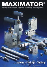
The Complete<br />
Programme for High<br />
Pressure Technology<br />
1 Air Driven Liquid Pumps<br />
1 Hydraulic Power Packs<br />
1 Air Amplifiers<br />
1 Compressors | Boosters<br />
1 Pressure Intensifiers<br />
1 Test Benches<br />
1 Gas Assist<br />
Injection Systems<br />
1Valves, Fittings, Tubing<br />
1 Service
2<br />
The MAXIMATOR Air Driven Liquid Pump Line for outlet pressures<br />
from 4 to 5,500 bar (58 to 79,750 psi)<br />
MAXIMATOR concept Page 2<br />
Function scheme and advantages of the MAXIMATOR pumps Page 3<br />
Applications Page 4<br />
How to select MAXIMATOR pumps / MAXIMATOR pump questionnaire Page 6<br />
General suggestions how to operate MAXIMATOR pumps Page 7<br />
Oil service pumps to 1,000 bar (14,500 psi)<br />
MO series Page 8<br />
S series Page 9<br />
Water or oil service pumps to 5,500 bar (79,750 psi)<br />
M series Page 10<br />
G series Page 12<br />
Pumps for chemical service and special liquids up to 1,450 bar (21,040 psi)<br />
MSF series Page 14<br />
GSF series Page 14<br />
GX series Page 15<br />
Special pumps<br />
DPD series Page 16<br />
Single and two component injection pumps / pumps for mining applications Page 16<br />
MAXIMATOR power packs Page 17<br />
Available accessories for MAXIMATOR pumps Page 18<br />
Flow charts for MAXIMATOR pumps Page 20<br />
Fluid compatibility guide / Recommended pump and seal versions Page 24<br />
Outer dimensions and standard connections for MAXIMATOR pumps Page 26<br />
Wetted materials of construction for MAXIMATOR pumps Page 27<br />
Advantages of the MAXIMATOR pumps<br />
1 High quality product<br />
1 Outstanding life time<br />
1 Few moving parts<br />
1 Portable design<br />
1 Easy to install and operate<br />
1 Explosion proof ... no electrical power required<br />
1 Economical source for hydraulic power<br />
1 Pressure held without energy consumption<br />
and without media heating<br />
1 Standard ratios available for pressures<br />
to 5,500 bar (79,805 psi)<br />
1 Requires no lubrication<br />
…we offer:<br />
∑ <strong>Technical</strong> advise<br />
∑ Full after sales service<br />
∑ Special construction<br />
and designs available<br />
MAXIMATOR<br />
Pump it.
Liquid pumps – The MAXIMATOR concept<br />
MAXIMATOR high efficiency pumps are ideal for a broad variety<br />
of oil, water and chemical applications. MAXIMATOR pumps are<br />
air driven at a drive air pressure of 1 to 10 bar (14,5 to 145 psi).<br />
Basically the principle of operation is similar to a reciprocating<br />
amplifier where control of the piston at the end position is<br />
regulated by a pilot operated 4/2 way valve.<br />
MAXIMATOR pumps feature a large air piston joint to a smaller<br />
diameter plunger. The pressure ratio is the difference of these<br />
two areas and is the method of determing maximum outlet<br />
pressure. Higher pressures are obtained by using higher<br />
pressure ratios. MAXIMATOR model numbers reflect the pumps’<br />
nominal pressure ratios, while the technical data indicates exact<br />
ratios. The outlet pressure is easily to set through a simple air<br />
regulator. By multiplying the pressure ratio by the available<br />
shop air pressure, the nominal liquid<br />
pressure can be calculated.<br />
Hydraulic section<br />
High pressure piston<br />
MAXIMATOR pumps are self priming.<br />
In general it is not necessary to use an<br />
air line lubricator. The liquid to be pumped, flows into the<br />
suction chamber by the up-stroke of the drive piston. By this<br />
suction effect, the inlet check valve is opened and the outlet<br />
check valve is closed. The down-stroke generates the pressure<br />
at the liquid side. The inlet check valve is closed and the outlet<br />
check valve is opened by the generated pressure. MAXIMATOR<br />
liquid pumps cycle automatically. When the pressure is built up<br />
Air drive<br />
Air drive section<br />
the numbers of cycles slow down. The pump stops automatically<br />
when the output pressure forces are equal. The Inlet connection<br />
Outlet connection<br />
pump restarts with a slight drop in the outlet pressure or an increase in the air drive pressure.<br />
Pump performance can be effected by a number of conditions, such as freezing of muffler or pilot valves (which is caused<br />
by moisture in air lines), inadequate inlet air line sizes and dirty filters. Don’t reduce the indicated port sizes and consult<br />
MAXIMATOR for exact flow conditions not shown in charts.<br />
MAXIMATOR offers complete technical and service support for all MAXIMATOR pumps.<br />
3<br />
Function scheme of the Air Driven Liquid Pumps<br />
Working principle of a single acting pump, multiple stage.<br />
Working principle of a double acting pump with one air head<br />
Air pressure<br />
Pressure stroke<br />
Suction stroke<br />
Single acting pumps with two or three air heads can<br />
achieve the same maximum outlet pressure with 1/2 or 1/3<br />
air drive pressure compared with a single acting pump<br />
with one air head.<br />
Double acting pumps improve the flow capacity by approx.<br />
50% in comparison with single acting pumps.
4<br />
Applications for Air Driven Liquid Pumps<br />
Series MO and S up to 1,000 bar (14,500 psi)<br />
The rugged construction, light weight and wide range of<br />
pressure ratios make these series of pumps ideal for<br />
powering a variety of oil/hydraulic operations.<br />
They are available as single or double acting models.<br />
Series M and G up to 5,500 bar (79,750 psi)<br />
The M and G series pumps are available in single or<br />
double acting models with single, double (M and G series<br />
or triple (only M series) air drive heads and wetted<br />
materials of stainless steel, making them an excellent<br />
choice for water application.<br />
Type MO<br />
Type M<br />
Oil Service Pumps<br />
1 Lifting and Jacking – lifting tables, scissor jack lifts,<br />
beam jacking and aircraft jacking<br />
1 Hydraulic Operation – clamping devices, punches and<br />
pin presses, chucks, valve actuation<br />
1 Presses – cold isostatic presses, filter presses,<br />
hydraulic presses, hydraulic press actuation and system<br />
overload<br />
1 Tooling and Tightening – actuating cropping,<br />
crimping, cable shears and pipe bending tools, roller<br />
tensioning and torque wrenches<br />
1 Testing – tensile test machines and pressure testing<br />
1 Miscellaneous – lubrication systems<br />
Water or Oil Service Pumps<br />
1 Hydrostatic Testing – valves, tanks, pressure vessels,<br />
pressure switches, hoses, pipes and tubing, pressure<br />
gauges, cylinders, transducers, well casings, BOPs, gas<br />
bottles and air craft components<br />
1 Burst and Cycle fatigue testing of above components<br />
1 Calibration of pressure gauges and transducers<br />
1 Water Blasting<br />
1 Leak Testing<br />
1 Emergency shutdown systems for oil and gas wells<br />
1 Pressurization of pressure vessels for testing various<br />
components<br />
1 Operation and Control of well service and well head<br />
equipment<br />
Type S<br />
Type G
Applications for Air Driven Liquid Pumps<br />
5<br />
Series MSF, GSF and GX up to 1,450 bar (21,025 psi)<br />
These two series of pumps are similar to the M and G<br />
series described before. MSF and GSF pumps feature a<br />
distance piece and PTFE seals to address the specific<br />
requirements of chemical service.<br />
GX series are high flow pumps designed for rugged<br />
installations and built with environmental resistant<br />
external components. They are ideal for<br />
offshore applications with stainless<br />
steel wetted parts and corrosive<br />
resistant external<br />
components.<br />
MAXIMATOR pumps for special applications<br />
DPD series are large double acting pumps that deliver a<br />
high flow rate at high pressure up to 2,100 bar (30,450 psi).<br />
1 Test pressure generation for Mandrel<br />
Extraction Machines<br />
1 Waterjet cutting in intermittent service<br />
Type MSF<br />
Type DPD<br />
Pumps for Chemical and Offshore service<br />
1 Inhibitor Injection of methanol and glycol in wells<br />
1 Coolant Injection<br />
1 Aviation and Automotive Testing – brake fluid,<br />
skydrol, transmission fluid and power steering fluid<br />
1 Chemical Fluid Transfer and Pressurization<br />
Single and Two Component Injection Pumps<br />
Grouting Pumps<br />
Infusion Pumps<br />
1 Underground Mining Industry<br />
1 Rock and Coal Consolidation<br />
1 Tunnel and Bridge Construction<br />
1 Concrete Restauration<br />
Type GSF<br />
Type S35 - PU<br />
Type GX<br />
MAXIMATOR<br />
Pump it.
6<br />
How to select Air Driven Liquid Pumps<br />
MAXIMATOR pumps are suitable for liquid applications. To select and order a hydraulic pump that is suitable the best for your applications,<br />
the following parameters have to be observed:<br />
1. Liquid to be handled<br />
The type of liquid is essential to select a MAXIMATOR pump hence the wetted material of construction and compound of the seals are<br />
determined by the specific fluid. MAXIMATOR pumps are available for several services. The two most important we are offering standard<br />
pumps are for oil or water use, see also ordering codes.<br />
2. Available Air Drive pressure<br />
MAXIMATOR pumps are designed for an air drive pressure of pL = 1 to 10 bar (14,5 to 145 psi) maximum.<br />
3. Required hydraulic outlet pressure and flow capacity<br />
The outlet pressures given in the technical pump tables are based upon a maximum air drive pressure of pL = 10 bar. The real oulet<br />
pressure in your specific case is determined by air drive pressure multiplied by pressure ratio, pL * i. The indicated flow capacities Qmax is<br />
the maximum value which can be reached at an outlet pressure of 0 bar and an air drive of pL = 6 bar. The real flow capacities at a<br />
specified outlet pressure are listed in the flow charts, page 20 to 23.<br />
4. Size and weight<br />
For some applications the size and weight are also important to select a pump.<br />
The following questionnaire shall help you to select the right pump<br />
for your application. On request we would also submit a quotation.<br />
Please return the filled questionaire to us (fax no. ++49 5586 803 40).<br />
Customer reference:<br />
Fax no.:<br />
MAXIMATOR Air Driven Liquid Pump Questionnaire<br />
Medium:<br />
Type:<br />
Chart No.:<br />
Viscosity: mm 2 /s<br />
Available Shop Air Pressure (1 to 10 bar [14,5 to 145 psi]):<br />
Outlet Pressure:<br />
Maximum Outlet Pressure:<br />
Flow Rate, required at Outlet Pressure<br />
bar<br />
bar<br />
bar<br />
l/min<br />
Working Temperature (max. 80°C permitted): °C<br />
Suction Altitude:<br />
mm<br />
Application:
Further general suggestions to operate the Air Driven Liquid Pumps properly<br />
7<br />
Assembly positions<br />
MAXIMATOR pumps can, in principle, be installed in any position, but a maximum service life of the seals is achieved in a<br />
vertical one.<br />
Port sizes Important!<br />
Please observe that only screws and tubing are fitted that are suitable for the pressure range of the pump.<br />
To ensure an optimum operation (pressure and flow) of the pumps, the port sizes of the pumps shall not be reduced.<br />
Drive air connection and initial operation<br />
The air drive connection is located at the spool valve housing.<br />
A second air drive connection as unregulated pilot port on S...D and G(SF) series that has to be connected too, not<br />
only provides better pressure control but is also the ideal place to install control instrumentation because of its small size.<br />
In any event a compressed air filter and water separator has to be fitted to the pump. Filters with water separator,<br />
pressure regulator, control pressure gauge and shut-off valve are optionally available under ”Air control unit C....“,<br />
depending on the pump line.<br />
No air lubricator is required since the pump received Barium grease treatment. Has a lubricator been used once, it is<br />
strongly recommended to continue. If there is only very dry air available, an air lubricator is needed.<br />
Operating temperatures for MAXIMATOR pumps<br />
are in general between –20°C to +80°C (standard). The pumps with –VE seal version can be operated up to max. +60°C,<br />
at short term up to +80° would be acceptable.<br />
For outdoor service at temperatures of 0°C and below, special versions are available on request.<br />
Recommended hydraulic oils<br />
Proper operation and efficiency of the pumps is mainly depending on the quality of the used hydaulic liquid.<br />
We recommend hydraulic oils with a viscosity between 46 – 68 cst, i. e.<br />
Manufacturer Hydraulic oil to DIN 51524 T2; DIN 51519; ISO VG 46<br />
ARAL VITAM GF 46<br />
BP ENERGOL HLP 46<br />
ESSO NUTO H 46<br />
SHELL TELLUS Oil 46<br />
HYDROL DO 46<br />
HYDROL HV 46<br />
DEA ASTRON HLP 46<br />
Recommended quality of drive air<br />
The drive air should have a quality class of 3 to 4 (solids/water/oil) according to the recommendation no. 611/1984 by<br />
PNEUROP (European Committee of Manufacturers of boosters, vacuum pumps and air driven tools).<br />
Solids: maximum particle size 5 µ<br />
maximum particle concentration 5 mg/m 3<br />
Dew point: + 10° = water content of 9.4 g/m 3 to + 2°C = water content of 5.6 g/m 3<br />
Oil content: 1.0 to 5 mg/m 3<br />
Please note that by using humid air of high humidity in continuous operation the problem of icing could occur. We suggest<br />
to install a water seperator and a dryer in the drive air line.<br />
If the drive air is too dry and has got a dew point lower than - 40°C, we suggest to use an oiler.<br />
By observing this drive air quality, an optimum life time of the seals and packings will be achieved.
8<br />
Oil Service – MO series: Pressures to 1,000 bar (14,500 psi)<br />
MAXIMATOR pumps MO series are available as single or double acting with single air drive head.<br />
MO pumps<br />
single acting, single air drive head<br />
Pressures to 1,000 bar (14,500 psi)<br />
MO pumps are single acting types with single air drive head. They are<br />
lightweight, rugged and are available in several pressure ratios.<br />
1 Cast iron bodies, tool steel plungers and polyurethane seals.<br />
1 Pumps come standard with bottom inlet<br />
1 Ideal for portable power packs<br />
1 For air drive pressure from 1 bar (14.5 psi) to10 bar (145 psi) maximum.<br />
<strong>Technical</strong> <strong>Data</strong><br />
Type Pressure ratio ** Displ. Volume * Outlet *** Flow **** Connections Weight<br />
cm3 cu.inch bar psi l/min Inlet A Outlet B kg<br />
MO4 1:4 30.5 1.86 40 580 14.81 3/4 BSP 1/2 BSP 2.5<br />
MO8 1:9 14.7 0.90 90 1305 7.07 3/4 BSP 1/2 BSP 2.5<br />
MO12 1:14 9.4 0.57 140 2030 4.55 3/4 BSP 1/2 BSP 2.5<br />
MO22 1:29 4.6 0.28 290 4205 2.22 3/8 BSP 1/4 BSP 3.0<br />
MO37 1:47 2.8 0.17 470 6815 1.36 3/8 BSP 1/4 BSP 3.0<br />
MO72 1:88 1.5 0.09 880 12760 0.72 3/8 BSP 1/4 BSP 3.0<br />
MO111 1:133 1.0 0.06 1000 14500 0.48 3/8 BSP 1/4 BSP 3.0<br />
MO189 1:225 0.6 0.04 1000 14500 0.28 3/8 BSP 1/4 BSP 3.0<br />
MO...D pumps<br />
double acting, single air drive head<br />
Pressures to 1,000 bar (14,500 psi)<br />
MO...D pumps are double acting, single air drive head type. They are characterized<br />
by the same features as the MO series, but<br />
1 Pumps come standard with side inlet<br />
1 They have less pulsations and deliver approx.<br />
50% more flow than the single acting MO pumps.<br />
<strong>Technical</strong> <strong>Data</strong><br />
Type Pressure ratio ** Displ. Volume * Outlet *** Flow **** Connections Weight<br />
cm3 cu.inch bar psi l/min Inlet A Outlet B kg<br />
MO22D 1:28 9,2 0,56 280 4060 3.91 3/8 BSP 1/4 BSP 4.5<br />
MO37D 1:46 5.6 0.34 460 6670 2.35 3/8 BSP 1/4 BSP 4.5<br />
MO72D 1:86 3.0 0.18 860 12470 1.24 3/8 BSP 1/4 BSP 4.5<br />
MO111D 1:130 2.0 0.12 1000 14500 0.82 3/8 BSP 1/4 BSP 4.5<br />
MO189D 1:220 1.2 0.07 1000 14500 0.49 3/8 BSP 1/4 BSP 4.5<br />
See also flow charts at page 20<br />
* Displacement volume per double stroke (calculated) • ** Ratio – driving surface / driven surface (calculated)<br />
*** Static outlet pressure (calculated and maximum allowed) at an air drive pressure of 10 bar / 145 psi<br />
**** Approximate flow at an air drive of 6 bar / 87 psi and an outlet pressure of 0 bar/psi.<br />
The minimum air drive pressure to start the pump is 1 bar / 14.5 psi. • Depending on the pressure ratio a special outlet pressure can be reached.<br />
Options for MO series:<br />
Order code:<br />
1 Side inlet (for single acting, single air drive head models): MO37 – S<br />
1 External Pilot Port Modification (for single acting MO22 – MO189): MO37 – DIR<br />
(Pump can be started and stopped by a small magnetic valve)<br />
1 Special inlet and outlet ports (i. e. NPT): MO37(D) – NPT<br />
1 Special seal material to handle special fluids: See fluid compatibility guide, page 24<br />
1 Air control unit for MO series with filter pressure regulator,<br />
control pressure gauge and shut-off valve: MO37(D) with C1 Other options available on request.
Oil Service – S series: Pressures to 1,000 bar (14,500 psi)<br />
MAXIMATOR pumps S series are available as single or double acting with single air drive head.<br />
S pumps<br />
single acting, single air drive head<br />
Pressures to 1,000 bar (14,500 psi)<br />
S pumps are single acting types with single air drive head. They are compact<br />
and lightweight for simple installation in both static and portable<br />
applications. They will operate at an air pressure as low as 1 bar (14.5 psi)<br />
due to minimal internal friction.<br />
S pumps are ideal for applications demanding fast response time<br />
1 Cast iron bodies, tool steel plungers and polyurethane seals.<br />
1 Pumps come standard with side inlet only<br />
1 Ideal for portable power packs<br />
1 For air drive pressure from 1 bar (14.5 psi) to10 bar (145 psi) maximum.<br />
9<br />
<strong>Technical</strong> <strong>Data</strong><br />
Type Pressure ratio ** Displ. Volume * Discharge *** Flow **** Connections Weight<br />
cm3 cu.inch bar psi l/min Inlet A Outlet B kg<br />
S15 1:17 28.3 1.73 170 2465 9.38 3/4 BSP 3/4 BSP 9.1<br />
S25 1:25 19.6 1.20 250 3625 6.72 3/4 BSP 3/4 BSP 9.1<br />
S35 1:39 12.6 0.77 390 5655 4.31 3/4 BSP 3/4 BSP 9.1<br />
S60 1:61 8.0 0.49 610 8845 2.75 1/2 BSP 3/8 BSP 9.1<br />
S100 1:108 4.5 0.27 1000 14500 1.55 1/2 BSP 3/8 BSP 9.1<br />
S150 1:156 3.1 0.19 1000 14500 1.08 1/2 BSP 3/8 BSP 9.1<br />
S...D pumps<br />
double acting, single air drive head<br />
Pressures to 1,000 bar (14,500 psi)<br />
S...D pumps are double acting, single air drive head type. They are characterized<br />
by the same features as the S series, but<br />
1 Pumps come standard with side inlet,<br />
bottom inlet not available<br />
1 They have less pulsations and deliver approx. 50% more flow than the<br />
single acting S pumps.<br />
1 Maximum air drive pressure 10 bar (145 psi)<br />
1 The unregulated pilot port on all S...D pumps not only provides better<br />
pressure control but is also the ideal place to install control instrumentation<br />
because of its small size, BSP 1/8”.<br />
<strong>Technical</strong> <strong>Data</strong><br />
Type Pressure ratio ** Displ. Volume * Discharge *** Flow **** Connections Weight<br />
cm3 cu.inch bar psi l/min Inlet A Outlet B kg<br />
S15D 1:16 56.6 3.45 160 2320 17.56 3/4 BSP 3/4 BSP 14.5<br />
S25D 1:24 39.2 2.39 240 3480 12.00 3/4 BSP 3/4 BSP 14.5<br />
S35D 1:38 25.2 1.54 380 5510 7.58 3/4 BSP 3/4 BSP 14.5<br />
S60D 1:60 16.0 0.98 600 8700 4.80 1/2 BSP 3/8 BSP 14.5<br />
S100D 1:107 9.0 0.55 1000 14500 2.68 1/2 BSP 3/8 BSP 14.5<br />
S150D 1:155 6.2 0.38 1000 14500 1.85 1/2 BSP 3/8 BSP 14.5<br />
See also flow charts at page 21<br />
* Displacement volume per double stroke (calculated) • ** Ratio – driving surface / driven surface (calculated)<br />
*** Static outlet pressure (calculated and maximum allowed) at an air drive pressure of 10 bar / 145 psi<br />
**** Approximate flow at an air drive of 6 bar / 87 psi and an outlet pressure of 0 bar/psi.<br />
The minimum air drive pressure to start the pump is 1 bar / 14.5 psi. • Depending on the pressure ratio a special outlet pressure can be reached.<br />
Options for S series:<br />
Order code:<br />
1 Special inlet and outlet ports (i. e. NPT): S35(D) – NPT<br />
1 Special seal material to handle special fluids: See fluid compatibility guide, page 24<br />
1 Air control unit for S series with filter pressure regulator,<br />
control pressure gauge and shut-off valve: S35(D) with C1.5 Other options available on request.
10<br />
Water or Oil Service – M series: Pressures to 4,000 bar (58,000 psi)<br />
MAXIMATOR pumps M series are available as single or double acting with either a single, double or triple air<br />
drive head. For air drive pressures from 1 bar (14.5 psi) minimum to 10 bar (145 psi) maximum.<br />
M pumps<br />
single acting, single air drive head<br />
Pressures to 2,200 bar (31,900 psi)<br />
M pumps are single acting types with single air drive head. They are compact<br />
lightweight and feature rugged construction.<br />
1 M4 to M12 pumps have aluminium bodies and stainless steel plungers.<br />
M22 to M189 have stainless steel bodies and plungers. All M pumps have<br />
polyurethane seals with Buna ”N” O-rings, UHMWPE package and Viton<br />
O-rings for water service is available as option.<br />
1 All M pumps are standard with bottom inlet, side inlet is available as<br />
option.<br />
<strong>Technical</strong> <strong>Data</strong><br />
Type Pressure ratio ** Displ. Volume * Outlet*** Flow **** Connections Weight<br />
cm3 cu.inch bar psi l/min Inlet A Outlet B kg<br />
M4 1:4 30.5 1.86 40 580 14.81 1 BSP 1/2 BSP 3.0<br />
M8 1:9 14.7 0.90 90 1305 7.07 3/4 BSP 1/2 BSP 3.0<br />
M12 1:14 9.4 0.57 140 2030 4.55 3/4 BSP 1/2 BSP 3.0<br />
M22 1:28 4.6 0.28 280 4060 2.22 3/8 BSP 3/8 BSP 2.8<br />
M37 1:46 2.8 0.17 460 6670 1.36 3/8 BSP 3/8 BSP 2.8<br />
M72 1:86 1.5 0.09 860 12470 0.72 3/8 BSP 3/8 BSP 2.8<br />
M111 1:130 1.0 0.06 1300 18850 0.48 3/8 BSP 3/8 BSP 2.8<br />
M189 1:220 0.6 0.04 2200 31900 0.28 3/8 BSP 3/8 BSP 2.8<br />
M...D pumps<br />
double acting,<br />
single air drive head<br />
Pressures to 2,200 bar (31,900 psi)<br />
M...D pumps are double acting, single air drive head type. They are<br />
characterized by the same features as the M series, but<br />
1 they have less pulsations and deliver approx.<br />
50% more flow than the single acting M pumps<br />
1 All M...D pumps come standard with side inlet, bottom inlet not available<br />
<strong>Technical</strong> <strong>Data</strong><br />
Type Pressure ratio ** Displ. Volume * Outlet*** Flow **** Connections Weight<br />
cm3 cu.inch bar psi l/min Inlet A Outlet B kg<br />
M22D 1:28 9.2 0.56 280 4060 3.91 3/8 BSP 3/8 BSP 3.7<br />
M37D 1:46 5.6 0.34 460 6670 2.35 3/8 BSP 3/8 BSP 3.7<br />
M72D 1:86 3.0 0.18 860 12470 1.24 3/8 BSP 3/8 BSP 3.7<br />
M111D 1:130 2.0 0.12 1300 18850 0.82 3/8 BSP 3/8 BSP 3.7<br />
M189D 1:220 1.2 0.07 2200 31900 0.49 3/8 BSP 3/8 BSP 3.7<br />
See also flow charts at page 20<br />
* Displacement volume per double stroke (calculated) • ** Ratio – driving surface / driven surface (calculated)<br />
*** Static outlet pressure (calculated and maximum allowed) at an air drive pressure of 10 bar / 145 psi<br />
**** Approximate flow at an air drive of 6 bar / 87 psi and an outlet pressure of 0 bar/psi.<br />
The minimum air drive pressure to start the pump is 1 bar / 14.5 psi. • Depending on the pressure ratio a special outlet pressure can be reached.<br />
MAXIMATOR<br />
Pump it.
Water or Oil Service – M series: Pressures to 4,000 bar (58,000 psi)<br />
11<br />
M...-2 pumps<br />
single acting, double air drive head<br />
Pressures to 4,000 bar (58,000 psi)<br />
M...-2 pumps are single acting double air drive head pumps. Compared<br />
with the single acting single stage M series they reach double pressure at<br />
the same air drive pressure.<br />
M...-2 pumps are available with polyurethane seals.<br />
They come standard with bottom inlet, side inlet is available as option.<br />
<strong>Technical</strong> <strong>Data</strong><br />
Type Pressure ratio ** Displ. Volume * Outlet *** Flow **** Connections Weight<br />
cm3 cu.inch bar psi l/min Inlet A Outlet B kg<br />
M111-2 1:261 1.0 0.06 2500 36250 0.35 1/4 BSP 9/16-18 UNF 3.9<br />
M189-2 1:440 0.6 0.04 4000 58000 0.21 1/4 BSP 9/16-18 UNF 3.9<br />
M...-3 pumps<br />
double acting, triple air drive head<br />
Pressures to 4,000 bar (58,000 psi)<br />
M...-3 pumps are single acting triple air drive head pumps. Compared with<br />
the single acting single stage M pumps they reach triple pressure at the<br />
same air drive pressure.<br />
M...-3 pumps are available with polyurethane seals.<br />
They come standard with bottom inlet, side inlet is available as option.<br />
<strong>Technical</strong> <strong>Data</strong><br />
Type Pressure ratio ** Displ. Volume * Outlet *** Flow **** Connections Weight<br />
cm3 cu.inch bar psi l/min Inlet A Outlet B kg<br />
M111-3 1:391 1.0 0.06 2500 36250 0.24 1/4 BSP 9/16-18 UNF 4.6<br />
M189-3 1:660 0.6 0.04 4000 58000 0.14 1/4 BSP 9/16-18 UNF 4.6<br />
See also flow charts at page 20<br />
* Displacement volume per double stroke (calculated) • ** Ratio – driving surface / driven surface (calculated)<br />
*** Static outlet pressure (calculated and maximum allowed) at an air drive pressure of 10 bar / 145 psi<br />
**** Approximate flow at an air drive of 6 bar / 87 psi and an outlet pressure of 0 bar/psi.<br />
The minimum air drive pressure to start the pump is 1 bar / 14.5 psi. • Depending on the pressure ratio a special outlet pressure can be reached.<br />
Options for MO series:<br />
Order code:<br />
1 Seal material for oil use (standard pump): M37 – (L)<br />
1 Seal material for water use: M37 – (L)VE / M37D – VE<br />
(not available for M ...-2/M...-3 and M ...-01H types)<br />
1 Special seal material to handle special fluids: See fluid compatibility guide, page 24<br />
1 Side inlet for single acting versions: M37(L) – S / M37(L)VE – S<br />
1 External pilot port modification: M37 – DIR<br />
(only available for M22 to M189 single acting, single air drive head types)<br />
1 Spring return and hand lever attachment: M37 – 01H<br />
(modification only available for M22 to M189 single acting, single air drive head types)<br />
1 Special inlet and outlet ports (i. e. NPT): M37 – NPT<br />
1 Air control unit for M series with filter pressure regulator,<br />
control pressure gauge and shut-off valve:<br />
1 To protect the pump against excessive outlet pressures,<br />
an air safety valve can be fitted to the air control unit<br />
Other options available on request.<br />
M37 with C1<br />
M37 with C1/SVair<br />
(The outlet pressure has to be indicated.)
12<br />
Water or Oil Service – G series: Pressures to 5,500 bar (79,750 psi)<br />
MAXIMATOR pumps G series are available as single or double acting with either a single or double air drive<br />
head. For air drive pressures of 1 bar (14.5 psi) minimum to 10 bar (145 psi) maximum. The unregulated pilot port<br />
on all G pumps not only provides better pressure control but is also the ideal place to install control instrumentation<br />
because of its small size, 1/8 BSP.<br />
G pumps<br />
single acting,<br />
single air drive head<br />
Pressures to 4,500 bar (65,295 psi)<br />
G pumps have stainless steel bodies and plungers.<br />
All G pumps have polyurethan seals. For strictly water service, UHMWPE<br />
seal option is recommended. This seal is an option because the standard<br />
polyurethane seal provides significantly better service life in non-straight<br />
water applications.<br />
G pumps come standard with bottom inlet. Side inlet is available as<br />
option. Model G500(S) is only available with side inlet.<br />
<strong>Technical</strong> <strong>Data</strong><br />
Type Pressure ratio ** Displ. Volume * Outlet *** Flow **** Connections Weight<br />
cm3 cu.inch bar psi l/min Inlet A Outlet B kg<br />
G10 1:11 90.0 5.49 110 1595 18.53 1 BSP 3/4 BSP 16.0<br />
G15 1:16 62.0 3.78 160 2320 12.86 1 BSP 3/4 BSP 16.0<br />
G25 1:28 35.3 2.15 280 4060 7.24 3/4 BSP 3/4 BSP 14.5<br />
G35 1:40 24.5 1.49 400 5800 5.02 3/4 BSP 3/4 BSP 14.5<br />
G60 1:63 15.4 0.94 630 9135 3.21 3/4 BSP 1/2 BSP 13.5<br />
G100 1:113 8.8 0.54 1050 15225 1.81 3/4 BSP 1/2 BSP 13.5<br />
G150 1:151 6.6 0.40 1450 21025 1.36 3/4 BSP 1/2 BSP 13.5<br />
G250 1:265 3.8 0.23 2650 38425 0.77 1/2 BSP 9/16-18 UNF 13.5<br />
G300 1:314 3.2 0.20 3140 45530 0.65 1/2 BSP 9/16-18 UNF 13.5<br />
G400 1:398 2.5 0.15 3980 57710 0.51 1/2 BSP 9/16-18 UNF 13.5<br />
G500S 1:519 1.9 0.12 4500 65295 0.39 1/4 BSP 9/16-18 UNF 13.5<br />
G...D pumps<br />
double acting,<br />
single air drive head<br />
<strong>Technical</strong> <strong>Data</strong><br />
Type Pressure ratio ** Displ. Volume * Outlet *** Flow **** Connections Weight<br />
cm3 cu.inch bar psi l/min Inlet A Outlet B kg<br />
G10D 1:10 180.0 10.98 110 1450 28.85 1 BSP 3/4 BSP 22.0<br />
G15D 1:15 124.0 7.56 150 2175 19.84 1 BSP 3/4 BSP 22.0<br />
G25D 1:27 70.6 4.31 270 3915 11.34 3/4 BSP 3/4 BSP 19.0<br />
G35D 1:40 29.0 1.77 400 5800 7.74 3/4 BSP 3/4 BSP 19.0<br />
G60DS 1:63 31.4 1.92 630 9135 5.04 3/4 BSP 1/2 BSP 17.0<br />
G100DS 1:113 17.6 1.07 1050 15225 2.78 3/4 BSP 1/2 BSP 17.0<br />
G150DS 1:151 7.6 0.46 1450 21025 2.10 3/4 BSP 1/2 BSP 17.0<br />
See also flow charts at page 22<br />
Pressures to 1,450 bar (21,025 psi)<br />
G...D pumps are double acting, single air drive head.<br />
They are characterized by the same features as the G pumps single acting,<br />
single air drive head types, but they have less pulsations and deliver<br />
approx. 50 % more flow.<br />
G...D pumps are available with polyurethane seals, UHMWPE seals with<br />
Viton O-ring for water use are available as option.<br />
Models G10D – G35D come standard with bottom inlet, side inlet is<br />
available as option. Models G60D(S) – G150D(S) are only available with<br />
side inlet.<br />
For air drive pressures of 1 bar (14.5 psi) minimum<br />
to 10 bar (145 psi) maximum.<br />
* Displacement volume per double stroke (calculated) • ** Ratio – driving surface / driven surface (calculated)<br />
*** Static outlet pressure (calculated and maximum allowed) at an air drive pressure of 10 bar / 145 psi<br />
**** Approximate flow at an air drive of 6 bar / 87 psi and an outlet pressure of 0 bar/psi.<br />
The minimum air drive pressure to start the pump is 1 bar / 14.5 psi. • Depending on the pressure ratio a special outlet pressure can be reached.
Water and Oil Service – G series: Pressures to 5,500 bar (79,750 psi)<br />
13<br />
G...-2 pumps<br />
single acting, double air drive head<br />
Pressures to 5,500 bar (79,750 psi)<br />
G...-2 pumps are single acting double air drive head pumps.<br />
Compared with the single acting single air drive head G pumps they reach<br />
double pressure at the same air drive pressure.<br />
G...-2 pumps are available with polyurethane seals, UHMWPE seals with<br />
Viton O-ring for water use are available as option.<br />
They come standard with bottom inlet, side inlet is available as option.<br />
For air drive pressures from 1 bar (14.5 psi) minimum to 10 bar (145 psi)<br />
maximum.<br />
<strong>Technical</strong> <strong>Data</strong><br />
Type Pressure ratio ** Displ. Volume * Outlet *** Flow **** Connections Weight<br />
cm3 cu.inch bar psi l/min Inlet A Outlet B kg<br />
G10-2 1:22 90.0 5.49 220 3190 15.89 1 BSP 3/4 BSP 20.5<br />
G15-2 1:32 62.0 3.78 320 4640 11.02 1 BSP 3/4 BSP 20.5<br />
G25-2 1:56 35.3 2.15 690 8120 6.19 3/4 BSP 3/4 BSP 19.0<br />
G35-2 1:80 24.5 1.49 800 11600 4.30 3/4 BSP 3/4 BSP 19.0<br />
G60-2 1:126 15.4 0.94 126 18270 2.70 3/4 BSP 1/2 BSP 18.0<br />
G100-2 1:226 8.8 0.54 2100 30450 1.55 1/2 BSP 9/16-18 UNF 18.0<br />
G150-2 1:300 6.6 0.40 2900 42050 1.16 1/2 BSP 9/16-18 UNF 18.0<br />
G250-2 1:530 3.8 0.23 4500 65250 0.66 1/4 BSP 9/16-18 UNF 22.0<br />
G300-2 1:628 3.2 0.20 4500 65250 0.56 1/4 BSP 9/16-18 UNF 22.0<br />
G400-2 1:796 2.5 0.15 5500 79750 0.44 1/4 BSP 9/16-18 UNF 22.0<br />
G500-2 1:1038 1.4 0.09 5500 79750 0.34 1/4 BSP 5/8-18 UNF 22.0<br />
See also flow charts at page 23<br />
* Displacement volume per double stroke (calculated) • ** Ratio – driving surface / driven surface (calculated)<br />
*** Static outlet pressure (calculated and maximum allowed) at an air drive pressure of 10 bar / 145 psi<br />
**** Approximate flow at an air drive of 6 bar / 87 psi and an outlet pressure of 0 bar/psi.<br />
The minimum air drive pressure to start the pump is 1 bar / 14.5 psi. • Depending on the pressure ratio a special outlet pressure can be reached.<br />
Options for G series:<br />
Order code:<br />
1 Seal material for oil use (standard pump): G35 – (L)<br />
1 Seal material for water use: G35 – (L)VE / G37D – VE<br />
(not available for G500 and G500-2)<br />
1 Special seal material to handle special fluids: See fluid compatibility guide, page 24<br />
1 Side inlet (G500, G500-2 and G60 – G150 come standard with side inlet) G35(L) – S / G35(D)VE – S<br />
1 Special inlet and outlet ports (i. e. NPT): G35 – NPT<br />
1 Air control unit for G series with filter pressure regulator,<br />
control pressure gauge and shut-off valve:<br />
G35(L) with C2<br />
1 To protect the pump against excessive outlet pressures,<br />
an air safety valve can be fitted to the air control unit<br />
G35(L) with C2/SVair<br />
(The outlet pressure has to be indicated.)<br />
Other options available on request.<br />
MAXIMATOR<br />
Pump it.
14<br />
Chemical Service – MSF and GSF series: Pressures to 1,450 bar (21,025 psi)<br />
MSF pumps<br />
single acting, single air drive head<br />
and distance piece<br />
Pressures to 1,450 bar (21,025 psi)<br />
MSF and GSF series pumps are rugged and designed for chemical service<br />
applications. These pumps are available as single acting types with single<br />
air drive head and distance piece.<br />
1 For air drive pressures from 1 bar (14.5 psi) minimum to 10 bar (145 psi)<br />
maximum MSF and GSF pumps have stainless steel bodies and plungers.<br />
1 MSF and GSF pumps have PTFE seals<br />
with Viton O-rings.<br />
1 Pumps come standard with bottom inlet.<br />
<strong>Technical</strong> <strong>Data</strong><br />
Type Pressure ratio ** Displ. Volume * Outlet *** Flow **** Connections Weight<br />
cm3 cu.inch bar psi l/min Inlet A Outlet B kg<br />
MSF4 1:4 30.5 1.86 40 580 14.81 1 BSP 1/2 BSP 6.7<br />
MSF8 1:9 14.7 0.90 90 1305 7.07 3/4 BSP 1/2 BSP 6.7<br />
MSF12 1:14 9.4 0.57 140 2030 4.55 3/4 BSP 1/2 BSP 6.7<br />
MSF22 1:28 4.6 0.28 280 4060 2.22 3/8 BSP 3/8BSP 3.5<br />
MSF37 1:46 2.8 0.17 460 6670 1.36 3/8 BSP 3/8 BSP 3.5<br />
MSF72 1:86 1.5 0.09 860 12470 0.48 3/8 BSP 3/8 BSP 3.5<br />
MSF111 1:130 1.0 0.06 1000 14500 0.28 3/8 BSP 3/8 BSP 3.5<br />
GSF pumps<br />
single acting, single air drive head<br />
and distance piece<br />
Pressures to 1,450 bar (21,025 psi)<br />
MSF and GSF series pumps are rugged and designed for chemical service<br />
applications. These pumps are available as single acting types with single<br />
air drive head and distance piece.<br />
1 For air drive pressures from 1 bar (14.5 psi) minimum to 10 bar (145 psi)<br />
maximum MSF and GSF pumps have stainless steel bodies and plungers.<br />
1 MSF and GSF pumps have PTFE seals<br />
with viton O-rings.<br />
1 Pumps come standard with bottom inlet.<br />
<strong>Technical</strong> <strong>Data</strong><br />
Type Pressure ratio ** Displ. Volume * Outlet *** Flow **** Connections Weight<br />
cm3 cu.inch bar psi l/min Inlet A Outlet B kg<br />
GSF10 1:11 90.0 5.49 110 1595 18.53 1 BSP 3/3 BSP 20.0<br />
GSF15 1:16 62.0 3.78 160 2320 12.86 1 BSP 3/4 BSP 20.0<br />
GSF25 1:28 35.3 2.15 280 4060 7.24 3/4 BSP 3/4 BSP 19.0<br />
GSF35 1:40 24.5 1.49 400 5800 5.02 3/4 BSP 3/4 BSP 19.0<br />
GSF60 1:63 15.7 0.96 630 9135 3.21 3/4 BSP 1/2 BSP 18.0<br />
GSF100 1:113 8.8 0.54 1050 15225 1.81 3/4 BSP 1/2 BSP 18.0<br />
GSF150 1:151 6.6 0.40 1450 21025 1.36 3/4 BSP 1/2 BSP 18.0<br />
See also flow charts at page 20 and 22<br />
* Displacement volume per double stroke (calculated) • ** Ratio – driving surface / driven surface (calculated)<br />
*** Static outlet pressure (calculated and maximum allowed) at an air drive pressure of 10 bar / 145 psi<br />
**** Approximate flow at an air drive of 6 bar / 87 psi and an outlet pressure of 0 bar/psi.<br />
The minimum air drive pressure to start the pump is 1 bar / 14.5 psi. • Depending on the pressure ratio a special outlet pressure can be reached.<br />
Options for MSF and GSF series:<br />
Order code:<br />
1 Special seal material, i. e. PTFE compound, to handle special fluids: See fluid compatibility guide, page 24<br />
1 Side inlet: MSF37 / GSF35 – S<br />
1 Special inlet and outlet ports (i. e. NPT): MSF37 / GSF35 – NPT<br />
1 Air control unit for MSF / GSF series with filter pressure<br />
regulator, control pressure gauge and shut-off valve:<br />
1 To protect the pump against excessive outlet pressures,<br />
an air safety valve can be fitted to the air control unit<br />
Other options available on request.<br />
MSF37 with C1 / GSF35 with C2<br />
MSF37 with C1/SVair / GSF35 with C2/SVair<br />
(The outlet pressure has to be indicated.)
Chemical Service – GX series: Pressures to 1,000 bar (14,500 psi)<br />
15<br />
GX pumps<br />
Pressures to 1,000 bar (14,500 psi)<br />
GX pumps are high flow capacity pumps designed for rugged installations<br />
and build with environmental resistant materials. They are ideal for offshore<br />
applications with stainless steel wetted parts and corrosive resistant<br />
external components.<br />
All GX series pumps have stainless bodies and plungers, UHMWPE (ultra<br />
high molecular weight polyethylene) seals and Viton O-rings as standard.<br />
<strong>Technical</strong> <strong>Data</strong><br />
Type Pressure Displ. Volume * Outlet pressure*** Flow **** Connections Weight<br />
ratio ** cm3 cu.inch bar psi l/min Inlet Outlet Air drive kg<br />
GX35 1:36 180 10.98 360 5220 24.50 1 FNPT 3/8 FNPT 3/4 BSP female 24.0<br />
GX60 1:66 65 3.97 600 8700 23.00 1 FNPT 3/8 FNPT 3/4 BSP female 24.0<br />
GX100 1:117 36 2.20 1000 14500 9.00 1 FNPT 3/8 FNPT 3/4 BSP female 24.0<br />
See also flow charts at page 23<br />
* Displacement volume per double stroke (calculated) • ** Ratio – driving surface / driven surface (calculated)<br />
*** Static outlet pressure (calculated and maximum allowed) at an air drive pressure of 10 bar / 145 psi<br />
**** Approximate flow at an air drive of 6 bar / 87 psi and an outlet pressure of 0 bar/psi.<br />
The minimum air drive pressure to start the pump is 1 bar / 14.5 psi. • Depending on the pressure ratio a special outlet pressure can be reached.<br />
Options for GX series:<br />
Order code:<br />
1 Seal package UHMWPE seals and depending on the fluid:<br />
1 Viton O-rings as standard GX35 – V<br />
1 NBR O-rings as option GX35 – N<br />
1 EPDM O-rings as option GX35 – E<br />
1 Air control unit for GX series with filter pressure regulator,<br />
control pressure gauge and shut-off valve:<br />
1 To protect the pump against excessive outlet pressures,<br />
an air safety valve can be fitted to the air control unit<br />
Other options available on request.<br />
See fluid compatibility guide, page 24<br />
GX35 with C2<br />
GX with C2/SVair<br />
(The outlet pressure has to be indicated.)<br />
MAXIMATOR<br />
Pump it.
16<br />
Pumps for special applications – DPD series: Pressures to 2,100 bar (30,450 psi)<br />
DPD pumps<br />
Pressures to 2,100 bar (30,450 psi)<br />
Special advantage of DPD series is a high flow capacity at<br />
high pressure. They are double acting pumps and<br />
available in two pressure ratios.<br />
<strong>Technical</strong> <strong>Data</strong><br />
Type Pressure Displ. Volume * Outlet pressure*** Flow **** Connections Weight<br />
ratio ** cm3 cu.inch bar psi l/min Inlet Outlet Air drive kg<br />
DPD150 1:185 72 4.4 1500 21.750 8.0 3/8 BSP female 1 1/18-12 UNF 3/4 BSP 49.0<br />
(F562C)<br />
DPD200 1:268 72 4.4 2100 30.450 5.6 3/8 BSP female 1 1/18-12 UNF 3/4 BSP 49.0<br />
(F562C)<br />
Please consult MAXIMATOR.<br />
Options for DPD series:<br />
1 Air control unit for DPD series with filter pressure<br />
regulator, control pressure gauge and shut-off valve:<br />
Order code:<br />
DPD150 with C3<br />
Please ask for our catalogue ”Single and Two Component Injection Pumps”.<br />
Single and Two Component<br />
Injection Pumps<br />
MAXIMATOR does also supply a line of special pumps for<br />
mining applications:<br />
1 Underground Mining Industry<br />
1 Rock and Coal Consolidation<br />
1 Tunnel and Bridge Construction<br />
1 Concrete Restoration<br />
MAXIMATOR<br />
Pump it.
Accessories for MAXIMATOR Liquid Pumps<br />
17<br />
To help you complete the installation of your MAXIMATOR<br />
liquid pump, we offer a wide variety of accessories. These<br />
ancillary products are available as prepackaged modules or<br />
as individual components.<br />
Please consult MAXIMATOR or ask for our catalogue<br />
”MAXIMATOR Packaged Pump Systems”.<br />
7<br />
0<br />
3<br />
5<br />
MAXIMATOR Packaged Pump System<br />
(Example)<br />
6<br />
2<br />
Components in Modular Design<br />
1 Pump model all M, S and G series<br />
2 Air control unit, comprising combined filter pressure<br />
regulator, control pressure gauge and shut-off valve<br />
C1 for M series<br />
C1.5 for S series<br />
C2 for G series<br />
3 Air safety valve<br />
SV mounted in the air line<br />
4 Tank sizes 6.5 liter, 13 liter, 30 liter, 70 liter, standard<br />
of aluminium, stainless steel on request<br />
5 Mobility of the packaged pump system<br />
F mobile (with wheels)<br />
T portable (with handles)<br />
R frame<br />
6 Relief valve<br />
EV with return line to the tank<br />
7 Pressure gauge<br />
Pressure range / Diameter of the housing<br />
(cl. 1.6/1.0/0.6, glycerine damped)<br />
8 Operating liquid<br />
O Oil (tank of aluminium, components galvanized)<br />
W Water (tank of aluminium, components of SS)<br />
VA Stainless steel (tank of 1.4571 or 1.4305)<br />
9 Manifold block with pressure outlet(s)<br />
A1 1 pressure outlet to<br />
A6 6 pressure outlets<br />
V Option: Shut-off valve vor pressure outlet (AV1-AV6)<br />
10 Hand lever<br />
H only available for M22 to M189, single acting,<br />
single stage<br />
11 Other options:<br />
SCHW Float valve for automatic filling of the tank,<br />
i. e. from the water line<br />
SCHL HP hose, model SK<br />
ZR Additional return connection<br />
12 Specials on request<br />
9<br />
48<br />
Coding example:<br />
1<br />
M72-01H/C1/SV/13/R/EV/0-400(100)/W/AV1/VA (Special)<br />
comprising:<br />
1 M72-01H MAXIMATOR air driven liquid pump,<br />
model M72-01H (with hand lever)<br />
1 C1 Air control unit ”C1“, comprising<br />
1 combined filter pressure regulator<br />
1 control pressure gauge 0 – 10 bar,<br />
diameter 40 mm<br />
1 shut-off valve<br />
1 13 Tank volume 13 liter (9 liter useable)<br />
1 R Portable frame<br />
1 EV Manually operated relief valve<br />
1 0 – 400 (100) Pressure gauge 0 to 400 bar, diameter<br />
100 mm, oil damped, (only 2/3 of scale<br />
range useable)<br />
1 W for water service<br />
1 AV1 Manifold block with one pressure outlet<br />
and shut-off valve<br />
1 VA Tank of Stainless Steel<br />
1 Special: Colour: Frame in MAXIMATOR design (red)
18<br />
Individual components<br />
Example: ”C2”<br />
Air Control Units<br />
with combined filter pressure regulator, control pressure<br />
gauge and shut-off valve, available in different versions<br />
depending on the pump series:<br />
”C1“ for MO and M series<br />
”C1.5“ for S series<br />
”C2“ for G and GX series<br />
Regulating range: 0.5 to 10 bar<br />
Filter accuracy: 50 µ<br />
Available as option:<br />
Safety relief valves to limit the outlet pressure<br />
Pressure Gauges<br />
available in different ranges<br />
0 – 10 bar to 0 – 2,500 bar, dia. 100 mm<br />
0 – 25 bar to 0 – 7,000 bar, dia. 160 mm<br />
High Pressure Hoses<br />
in size DN4 for outlet pressures<br />
of 1,000; 1,800; 2,500 and 4,000 bar<br />
in size DN8 for outlet pressures<br />
of 900; 1,500 and 2,100 bar
Individual components<br />
19<br />
High Pressure Valves<br />
and Fittings<br />
Taper Seal Valves, Glands,<br />
Sleeves, Plugs, Elbows, Tees,<br />
Crosses, Couplings, Filters<br />
Rupture Discs, Safety Heads,<br />
Anti-Vibration Gland Assemblies<br />
for outlet pressures from<br />
700 to 4,200 bar 10,150 –<br />
60,900 psi).<br />
Ultra High Pressure Valves<br />
and Fittings to 10,000 bar<br />
(145,000 psi).<br />
High pressure tubing<br />
Available for different outlet pressures in ranges<br />
from 700 bar to 10,500 bar (from 10,150 to 152,500 psi)<br />
and in different tube dimensions and lengths<br />
Please ask for our catalogue<br />
“MAXIMATOR Valves • Fittings • Tubing“<br />
Other accessories like safety relief valves, accumulators, adapters,<br />
stroke counters, etc. available on request.
20<br />
Flow Charts M[(O)(SF)] Series<br />
Pump Type Sample Air Drive Outlet Pressure in bar<br />
Pressure in bar 0/Atm. 50 100 500 1000 1500 2000 3000 4000<br />
M[(O)(SF)]4 4 14.51<br />
6 14.81<br />
8 14.93<br />
M[(O)(SF)]8 4 6.93<br />
6 7.07 0.89<br />
8 7.13 3.39<br />
M[(O)(SF)]12 4 4.46 0.71<br />
6 4.55 2.64<br />
8 4.59 3.43 0.84<br />
M[(O)(SF)]22 4 2.17 1.58 0.44<br />
6 2.22 1.92 1.33<br />
8 2.24 2.05 1.70<br />
M[(O)(SF)]37 4 1.34 1.15 0.84<br />
6 1.36 1.27 1.11<br />
8 1.38 1.32 1.22<br />
M[(O)(SF)]72 4 0.71 0.67 0.60<br />
6 0.72 0.70 0.67 0.06<br />
8 0.73 0.72 0.70 0.33<br />
M[(O)(SF)]111 4 0.47 0.45 0.43 0.05<br />
6 0.48 0.47 0.46 0.26<br />
8 0.48 0.48 0.47 0.35 0.05<br />
M[(O)(SF)]189 4 0.28 0.27 0.26 0.17<br />
6 0.28 0.28 0.28 0.23 0.11<br />
8 0.28 0.28 0.28 0.25 0.18 0.08<br />
M111-2 4 0.35 0.34 0.33 0.24 0.03<br />
6 0.35 0.35 0.35 0.30 0.19 0.04<br />
8 0.36 0.35 0.35 0.32 0.26 0.16 0.04<br />
M189-2 4 0.20 0.20 0.20 0.18 0.12 0.05<br />
6 0.21 0.21 0.21 0.19 0.17 0.13 0.08<br />
8 0.21 0.21 0.21 0.20 0.19 0.16 0.14 0.06<br />
M111-3 4 0.23 0.23 0.23 0.19 0.12 0.02<br />
6 0.24 0.23 0.23 0.22 0.18 0.13 0.06<br />
8 0.24 0.24 0.24 0.23 0.20 0.17 0.13 0.03<br />
M189-3 4 0.14 0.14 0.14 0.13 0.12 0.10 0.06 0.00<br />
6 0.14 0.14 0.14 0.13 0.12 0.12 0.10 0.07 0.02<br />
8 0.14 0.14 0.14 0.14 0.13 0.12 0.11 0.09 0.06<br />
M(O)22D 4 3.83 2.75 0.66<br />
6 3.91 3.36 2.29<br />
8 3.94 3.61 2.96<br />
M(O)37D 4 2.31 1.99 1.45<br />
6 2.35 2.20 1.92<br />
8 2.37 2.28 2.11<br />
M(O)72D 4 1.22 1.15 1.04<br />
6 1.24 1.21 1.15 0.11<br />
8 1.26 1.23 1.20 0.57<br />
M(O)111D 4 0.81 0.78 0.74 0.08<br />
6 0.82 0.81 0.79 0.45<br />
8 0.83 0.82 0.81 0.60 0.09<br />
M(O)189D 4 0.48 0.47 0.45 0.29<br />
6 0.49 0.48 0.48 0.39 0.20 0.06<br />
8 0.49 0.49 0.48 0.43 0.32 0.14<br />
Flow in l/min
Flow Charts S Series<br />
Pump Type Sample Air Drive Outlet Pressure in bar<br />
Pressure in bar 0/Atm. 50 100 200 300 400 500 600 700 800<br />
S15 4 9.11 3.82<br />
6 9.38 6.60 0.91<br />
8 9.50 7.78 4.28<br />
S25 4 6.59 4.39 0.00<br />
6 6.72 5.60 3.36<br />
8 6.78 6.10 4.74 0.00<br />
S35 4 4.22 3.48 2.16<br />
6 4.31 3.93 3.26 1.03<br />
8 4.34 4.12 3.71 2.36 0.30<br />
S60 4 2.70 2.44 2.03 0.75<br />
6 2.75 2.62 2.41 1.76 0.80<br />
8 2.78 2.70 2.57 2.18 1.60 0.83<br />
S100 4 1.52 1.45 1.35 1.07 0.68 0.19<br />
6 1.55 1.51 1.46 1.32 1.12 0.87 0.57 0.20<br />
8 1.56 1.54 1.51 1.42 1.30 1.15 0.97 0.75 0.50 0.21<br />
S150 4 1.05 1.02 0.98 0.80 0.64 0.44 0.20<br />
6 1.08 1.06 1.04 0.98 0.91 0.81 0.70 0.57 0.42 0.26<br />
8 1.08 1.07 1.06 1.03 0.98 0.93 0.86 0.78 0.69 0.59<br />
S15D 4 17.21 6.17<br />
6 17.56 11.93<br />
8 17.71 14.30 6.78<br />
S25D 4 11.76 7.59<br />
6 12.00 9.87 5.58<br />
8 12.10 10.81 8.21<br />
S35D 4 7.43 6.08 3.66<br />
6 7.58 6.89 5.65 1.54<br />
8 7.64 7.22 6.48 3.99 0.18<br />
S60D 4 4.70 4.24 3.51 1.22<br />
6 4.80 4.56 4.20 3.02 1.30<br />
8 4.84 4.70 4.47 3.28 2.07 0.53<br />
S100D 4 2.62 2.50 2.33 1.84 1.16 0.30<br />
6 2.68 2.62 2.53 2.28 1.93 1.49 0.95 0.32<br />
8 2.70 2.66 2.61 2.46 2.25 1.98 1.66 1.27 0.83 0.33<br />
S150D 4 1.82 1.76 1.69 1.50 1.24 0.92 0.54 0.10<br />
6 1.85 1.83 1.79 1.69 1.56 1.40 1.20 0.98 0.72 0.43<br />
8 1.87 1.85 1.83 1.77 1.69 1.59 1.48 1.34 1.18 0.91<br />
Flow in l/min<br />
21<br />
Important!<br />
The flow rates as indicated in the charts have been<br />
measured with optimum cross sections of the pipes,<br />
depending on each individual pump model.<br />
To ensure a proper operation (pressure and flow) the<br />
standard port sizes of the pump shall not be reduced.<br />
MAXIMATOR<br />
Pump it.
Flow Charts G(SF) Series<br />
22<br />
Pump Type Sample Air Drive Outlet Pressure in bar<br />
Pressure in bar 0/Atm. 50 100 500 1000 1500 2000 3000 4000<br />
G(SF)10 4 18.16<br />
6 18.53 7.22<br />
8 18.68 11.84<br />
G(SF)15 4 12.60 4.19<br />
6 12.86 8.57<br />
8 12.96 10.37 4.61<br />
G(SF)25 4 7.10 5.14 1.35<br />
6 7.24 6.24 4.31<br />
8 7.30 6.70 5.53<br />
G(SF)35 4 4.92 4.11 2.70<br />
6 5.02 4.61 3.89<br />
8 5.06 4.82 4.38<br />
G(SF)60 4 3.15 2.86 2.41<br />
6 3.21 3.07 2.84<br />
8 3.24 3.15 3.01 0.14<br />
G(SF)100 4 1.77 1.69 1.58<br />
6 1.81 1.77 1.71 0.75<br />
8 0.99 0.97 0.96 0.64<br />
G(SF)150 4 1.33 1.29 1.00<br />
6 1.36 1.34 1.19 0.38<br />
8 1.37 1.36 1.34 1.07 0.40<br />
G250 4 0.76 0.74 0.73 0.53 0.08<br />
6 0.77 0.76 0.76 0.66 0.42 0.08<br />
8 0.78 0.77 0.77 0.70 0.57 0.36 0.08<br />
G300 4 0.64 0.63 0.62 0.49 0.02<br />
6 0.65 0.65 0.64 0.57 0.43 0.22<br />
8 0.66 0.65 0.65 0.61 0.52 0.39 0.22<br />
G400 4 0.50 0.50 0.49 0.42 0.27 0.05<br />
6 0.51 0.51 0.50 0.47 0.39 0.28 0.14<br />
8 0.52 0.52 0.51 0.49 0.44 0.38 0.29 0.06<br />
G500 4 0.39 0.38 0.38 0.34 0.27 0.16 0.03<br />
6 0.39 0.39 0.39 0.37 0.33 0.28 0.21 0.03<br />
8 0.40 0.40 0.39 0.38 0.36 0.33 0.29 0.18 0.03<br />
Flow in l/min<br />
Pump Type Sample Air Drive Outlet Pressure in bar<br />
Pressure in bar 0/Atm. 25 50 100 250 500 750 1000<br />
G10D 4 28.28 16.84<br />
6 28.85 23.02 10.97<br />
8 29.09 25.56 18.27<br />
G15D 4 19.44 14.93 6.47<br />
6 19.84 17.54 13.22<br />
8 20.00 18.61 16.00 7.11<br />
G25D 4 10.11 9.91 7.98 1.90<br />
6 11.34 10.73 9.74 6.64<br />
8 11.43 11.06 10.46 8.59<br />
G35D 4 7.59 7.08 6.35 4.16<br />
6 7.74 7.48 7.11 6.00<br />
8 7.80 7.65 7.42 6.75 2.99<br />
G60D 4 4.94 4.74 4.48 3.77 0.07<br />
6 5.04 4.94 4.81 4.44 2.55<br />
8 5.08 5.02 4.94 4.72 3.58 0.07<br />
G100D 4 2.73 2.67 2.61 2.44 1.68<br />
6 2.78 2.76 2.72 2.64 2.25 1.16<br />
8 2.79 2.77 2.72 2.48 1.82 0.83<br />
G150D 4 2.06 2.03 1.99 1.91 1.54 0.55<br />
6 2.10 2.09 2.07 2.02 1.84 1.33 0.59<br />
8 2.12 2.11 2.10 2.07 1.96 1.65 1.20 0.61<br />
Flow in l/min
Flow Charts G(SF) Series<br />
Pump Type Sample Air Drive Outlet Pressure in bar<br />
Pressure in bar 0/Atm. 50 100 500 1000 1500 2000 3000 4000<br />
G10-2 4 15.57 9.36<br />
6 15.89 12.72 6.19<br />
8 16.02 14.10 10.15<br />
G15-2 4 10.08 8.30 3.59<br />
6 11.02 9.74 7.34<br />
8 11.11 10.34 8.89<br />
G25-2 4 6.06 5.43 4.40<br />
6 6.19 5.86 5.34<br />
8 6.24 6.04 5.72<br />
G35-2 4 4.21 3.94 3.53<br />
6 4.30 4.16 3.95<br />
8 4.34 4.25 4.12 1.66<br />
G60-2 4 2.70 2.59 2.46 0.10<br />
6 2.76 2.70 2.63 1.43<br />
8 2.78 2.75 2.70 1.98 0.12<br />
G100-2 4 1.52 1.49 1.45 0.94<br />
6 1.55 1.53 1.51 1.25 0.64<br />
8 1.56 1.55 1.54 0.38 1.01 0.46<br />
G150-2 4 1.14 1.12 1.10 0.85 0.31<br />
6 1.16 1.16 1.15 1.02 0.74 0.33<br />
8 1.17 1.17 1.16 1.09 0.92 0.67 0.34<br />
G250-2 4 0.65 0.64 0.64 0.57 0.45 0.28 0.07<br />
6 0.66 0.66 0.66 0.62 0.56 0.47 0.36 0.07<br />
8 0.67 0.67 0.66 0.64 0.61 0.55 0.49 0.31 0.07<br />
G300-2 4 0.55 0.54 0.54 0.50 0.42 0.31 0.17<br />
6 0.56 0.56 0.55 0.53 0.49 0.44 0.37 0.19<br />
8 0.56 0.56 0.56 0.55 0.52 0.49 0.45 0.34 0.19<br />
G400-2 4 0.43 0.43 0.42 0.38 0.33 0.27 0.19<br />
6 0.44 0.44 0.44 0.42 0.39 0.36 0.32 0.21 0.08<br />
8 0.44 0.44 0.44 0.44 0.42 0.40 0.38 0.32 0.25<br />
G500-2 4 0.33 0.33 0.33 0.31 0.29 0.26 0.23 0.16 0.05<br />
6 0.34 0.34 0.34 0.33 0.32 0.30 0.28 0.24 0.18<br />
8 0.34 0.34 0.34 0.34 0.33 0.32 0.31 0.28 0.25<br />
Flow in l/min<br />
23<br />
Flow Charts GX<br />
Pump Type Sample Air Drive Outlet Pressure in bar<br />
Pressure in bar 0/Atm. 50 100 200 300 400 500 600 700 800<br />
GX35 4 25.00 16.67 8.44<br />
6 24.50 20.00 14.58<br />
8 23.00 21.72 17.67 9.45<br />
GX60 4 22.00 16.59 13.60 6.45<br />
6 23.00 19.06 15.77 10.00 5.21<br />
8 21.50 19.92 17.95 13.10 8.24 2.65<br />
GX100 4 8.50 7.71 7.11 6.13 4.71 1.88<br />
6 9.00 8.47 7.97 7.15 6.49 5.81 4.90 2.96<br />
8 9.00 8.47 7.97 7.15 6.49 5.84 5.09 3.99 2.35<br />
Flow in l/min<br />
Important!<br />
The flow rates as indicated in the charts have been<br />
measured with optimum cross sections of the pipes,<br />
depending on each individual pump model.<br />
To ensure a proper operation (pressure and flow) the<br />
standard port sizes of the pump shall not be reduced.<br />
MAXIMATOR<br />
Pump it.
24<br />
Seal Versions for MAXIMATOR Air Driven Liquid Pumps<br />
Seal version Seal material Remarks<br />
without indication or ”L” Polyurethane (PU) Nitrile (NBR) Standard<br />
VE Polyethylene (UHMWPE) Fluorcarbon (V) Standard<br />
VE / NBR Polyethylene (UHMWPE) Nitrile (NBR) Special<br />
VE / EPR Polyethylene (UHMWPE) Ethylene Propylen Special<br />
VE / CRL Polyethylene (UHMWPE) Chloropren (CRL) Special<br />
VE / KAL Polyethylene (UHMWPE) Kalrez (KAL) Special<br />
SF Filled Teflon (PTFE) Fluorcarbon (V) Standard<br />
MAXIMATOR Fluid Compatibility Guide<br />
Liquid<br />
Recommended Seal versions<br />
Standard Standard Special Special Special Special Pump Series<br />
L VE VE / NBR VE / EPR VE / CRL VE / KAL MSF and GSF<br />
A Acetone X X X<br />
Ammonia X X X<br />
Ammonium Chloride X X X X X X<br />
Ammonium Hydroxide X X X X X<br />
Ammonium Nitrate X X X X<br />
Ammonium Sulfate X X X X<br />
ASTM Oil No. 1 X X X X X<br />
ASTM Oil No. 2 X X X<br />
ASTM Oil No. 3 X X<br />
ASTM Oil No. 4 X X<br />
B Barium Chloride X X X X X X X<br />
Barium Hydroxide X X X X X<br />
Barium Sulfide X X X X X X<br />
Benzol X X X<br />
Bleaching Lye X X X<br />
Borax X X X X<br />
Boric Acid X X X X X X X<br />
Brake Fluid X X<br />
Bromine Water X X<br />
Bromobenzene X X<br />
Bunker Fuel X X X<br />
Butadiene X X<br />
Butanol X X X X X<br />
Butyl Acetate X X<br />
C Calcium Carbonate X X X X X<br />
Calcium Chloride X X X X X X X<br />
Cacium Hydroxide X X X X X<br />
Calcium Hypochloride X X X<br />
Calcium Phosphate X X X X<br />
Calcium Silicate X X X X<br />
Calcium Sulfide X X X X X<br />
Carbon Dioxide X X<br />
Celluguard X X X X X<br />
Cetane X X X<br />
Chloracetone X X<br />
Chromic Alum. X X X X X<br />
Copper Chloride X X X X X<br />
Cotton Oil X X X<br />
D Diacetone Alcohol X X<br />
Diethylene Glycol X X X X X<br />
Drilling Oil X X X X<br />
E Etheric Oils<br />
X<br />
Ethyl Acetate X X<br />
Ethyl Alcohol X X X X<br />
Ethyl Benzol<br />
X<br />
Ethyl Chloride<br />
X<br />
Ethyl Glycol X X X X X X<br />
F Fatty Acids X X X<br />
Ferric Chloride X X X X X X<br />
Flousilicic Acid X X X<br />
Freon X X
MAXIMATOR Fluid Compatibility Guide<br />
Liquid<br />
Recommended Seal versions<br />
Standard Standard Special Special Special Special Pump Series<br />
L VE VE / NBR VE / EPR VE / CRL VE / KAL MSF and GSF<br />
F Fuel X X X X<br />
Fuel Oil X X X<br />
G Gelatin X X X X<br />
Glucose X X X X<br />
Glycerine X X X X X<br />
Glycol X X X X<br />
H Halon X X X<br />
Hexyl Alcohol X X X<br />
Hydraulic Oils (Petroleum) X X X X<br />
Hydrazine X X<br />
Hydrogen Peroxide X X X<br />
Hydrolube X X X X<br />
Hydrozyanic Acid X X X<br />
I Iso-Butyl Alcohol X X X X X<br />
Isopropanol X X X X<br />
Isopropyl Alcohol X X X<br />
K Kerosene X X X X<br />
L Lead Nitrate X X X X<br />
Lead Sulphate X X X X<br />
Light Crude Oil X X X<br />
Lindol (hydraulic fluids) X X<br />
Linseed Oil X X X<br />
Liquid Gas (Propane/Butane) X X X<br />
M Methane X X X<br />
Methyl Alcohol X X X<br />
Methyl Carbonate X X<br />
Methyl Chloride X X<br />
Mineral Oils X X X X<br />
Mobil Oil SAE 20 X X X X<br />
N Natural Oil X X<br />
P Paraffin Oil X X X X<br />
Pentane X X X X<br />
Petrol X X X<br />
Petrol ”Super” X X X<br />
Phenol X X<br />
Phosphate Esters X X X<br />
Potassium Acetate X X<br />
Potassium Cloride X X X X X X<br />
Potassium Nitrate X X X X X X<br />
Potassium Sulfate X X X X X X<br />
Propane X X X<br />
Propyl Alcohol X X X X X<br />
S Salt Water X X X<br />
Silicone Oils X X X X X X<br />
Skydrol X X<br />
Soap Water X X X X<br />
Sodium Acetate X X<br />
Sodium Bisulfate X X X X X X<br />
Sodium Carbonate X X X X X<br />
Sodium Cloride X X X X X X<br />
Sodium Peroxide X X X<br />
Sodium Sulfide X X X X X X<br />
Sugar Liquids X X X X X<br />
T Tartaric Acid X X X<br />
Tetrachlorethylene X X X<br />
Tetralin X X X<br />
Toluol X X<br />
Trichlorethylene X X X<br />
Turbine Oil X X X X<br />
Turpentine X X X<br />
Turpentine Oil X X<br />
V Vegetable Oils X X X<br />
Vinegar X X X X<br />
W Water X X X<br />
Z Zinc Acetate X X<br />
Zinc Chloride X X X X X<br />
25
26<br />
Outer Dimensions and Standard Connections<br />
Pump Model Air Drive Inlet Outlet A B C<br />
Inlet Height Depth Width<br />
MO4, MO8, MO12 3/8 BSP 3/4 BSP 1/2BSP 190 102 80<br />
MO22, MO37, MO72, MO111, MO189 3/8 BSP 3/8 BSP 1/4 BSP 228 102 80<br />
MO22D, MO37D, MO72D, MO111D, MO189D 3/8 BSP 3/8 BSP 1/4 BSP 186 108 86<br />
S15, S25, S35 1/2 BSP 3/4 BSP 3/4 BSP 221 135 175.5<br />
S60, S100, S150 1/2 BSP 1/2 BSP 3/8 BSP 221 135 175.5<br />
S15D, S25D, S35D 1/2 BSP 3/4 BSP 3/4 BSP 260 135 175.5<br />
S60D, S100D, S150D 1/2 BSP 1/2 BSP 3/8 BSP 260 135 175.5<br />
M4 3/8 BSP 1 BSP 1/2 BSP 216 120 112<br />
M8, M12 3/8 BSP 3/4 BSP 1/2 BSP 209 120 112<br />
M22, M37, M72, M111, M189 3/8 BSP 3/8 BSP 3/8 BSP 195 104 112<br />
M22D, M37D, M72D, M111D, M189D 3/8 BSP 3/8 BSP 3/8 BSP 184 124 112<br />
M111-2, M189-2 3/8 BSP 1/4 BSP 9/16-18UNF 255 100 112<br />
M111-3, M189-3 3/8 BSP 1/4 BSP 9/16-18UNF 316 100 112<br />
G10, G15 3/4 BSP 1 BSP 3/4 BSP 311 190.5 272<br />
G25, G35 3/4 BSP 3/4 BSP 3/4 BSP 296 181 272<br />
G60, G100, G150 3/4 BSP 3/4 BSP 1/2 BSP 321 184.5 272<br />
G250, G300, G400 3/4 BSP 1/2 BSP 9/16-18UNF 300 193.5 272<br />
G500S 3/4 BSP 1/4 BSP 9/16-18UNF 362 181 272<br />
G10D, G15D 3/4 BSP 1 BSP 3/4 BSP 442 190.5 272<br />
G25D, G35D 3/4 BSP 3/4 BSP 3/4 BSP 412 181 272<br />
G60D, G100D, G150D 3/4 BSP 3/4 BSP 3/4 BSP 344 184.5 272<br />
G10-2, G15-2 3/4 BSP 1 BSP 3/4 BSP 411 211 272<br />
G25-2, G35-2 3/4 BSP 3/4 BSP 3/4 BSP 396 211 272<br />
G60-2 3/4 BSP 3/4 BSP 1/2 BSP 421 211 272<br />
G100-2, G150-2 3/4 BSP 1/2 BSP 9/16-18UNF 400 211 272<br />
G250-2, G300-2, G400-2 3/4 BSP 1/4 BSP 9/16-18UNF 483 211 272<br />
G500-2S 3/4 BSP 1/4 BSP 5/8-18UNF 462 211 272<br />
MSF4 3/8 BSP 1 BSP 1/2 BSP 248 112 120<br />
MSF8, MSF12 3/8 BSP 3/4 BSP 1/2 BSP 241 112 120<br />
MSF22, MSF37, MSF72, MSF111 3/8 BSP 3/8 BSP 3/8 BSP 247 112 108<br />
GSF10, GSF15 3/4 BSP 1 BSP 3/4 BSP 411 190.5 272<br />
GSF25, GSF35 3/4 BSP 3/4 BSP 3/4 BSP 400 181 272<br />
GSF60, GSF100, GSF150 3/4 BSP 3/4 BSP 1/2 BSP 412 181 272<br />
GX35, GX60, GX100 3/4 BSP 1 NPT 3/8 NPT 632 237 244<br />
DPD100, DPD150, DPD200 3/4 BSP 3/8 BSP 9/16-18UNF 762 346 460<br />
All connections listed are female unless otherwise noted. • Other connections available on request.<br />
Standard pump versions with bottom inlet:<br />
MO<br />
M / M...-2 / M...-3<br />
G10 – 400<br />
Air Drive Inlet<br />
G10D – G35D<br />
G10-2 – G400-2<br />
MSF<br />
GSF<br />
Pressure Outlet<br />
Standard pump versions with side inlet:<br />
MO...D<br />
S / S...D<br />
M...D<br />
G500S<br />
G60DS<br />
– G150DS<br />
G500-2S<br />
Suction Inlet<br />
Air Drive Inlet<br />
Pressure Outlet<br />
Suction Inlet
27<br />
Wetted Materials of Construction for MAXIMATOR Air Driven Liquid Pumps<br />
in Standard Design and their relating double acting or double and triple air head versions<br />
Pump Model Seal Package Pump Body Piston Fittings Inlet and Outlet Check Valves<br />
Balls Discs Springs Sealing<br />
cones<br />
MO4 – MO12 Polyurethane, Buna N AlCuMgPbF34 ”anodized“ 1.4112 (hardened) AlCuMgPbF34 ”anodized“ n/a 1.4301 1.4310 n/a<br />
MO22 – MO189 Polyurethane, Buna N GGG50 1.4112 (hardened) 1.4104 1.3541 n/a X 12 CrNi 17 7 n/a<br />
S15 – S150 Polyurethane, Buna N GGG50 1.4112 (hardened) n/a n/a 1.4301 1.4310 n/a<br />
M4(L) – M12(L) Polyurethane, Buna N AlMgSiPb ”anodized“ 1.4112 (hardened) Inlet: 1.4305 / 1.3541 n/a 1.4310 n/a<br />
Outlet: AlMgPbCu ”anodized“<br />
M4VE – M12VE UHMWPE, Viton AlMgSiPb ”anodized“ 1.4112 (hardened) Inlet: 1.4305 / 1.3541 n/a 1.4310 n/a<br />
Outlet: AlMgPbCu ”anodized“<br />
M22(L) – M189(L) Polyurethane, Buna N 1.4305 1.4112 (hardened) 1.4104 1.3541 n/a X 12 CrNi 17 7 n/a<br />
M22VE – M189VE UHMWPE, Viton 1.4305 1.4112 (hardened) 1.4104 1.3541 n/a X 12 CrNi 17 7 n/a<br />
MSF4(L) – MSF12(L) PTFE, Viton 1.4571 1.4571 1.4305 Al2O3 n/a 1.4571 n/a<br />
MSF4VE – MSF12VE Reinforced PTFE, Viton 1.4571 1.4571 Inlet: 1.4305 / Outlet: 1.4104 Al2O3 n/a 1.4571 n/a<br />
MSF22(L) – MSF111(L) Reinforced PTFE, Viton 1.4305 1.4112 (hardened) 1.4571 Al2O3 n/a 1.4571 n/a<br />
G10(L) – G35(L) Polyurethane, Buna N 1.4305 303 (X 10 CrNiS 18 9) 1.4112 (hardened) 1.4571 1.3541 1.4568 1.4310 n/a<br />
G10VE – G35VE UHMWPE, Viton 1.4305 303 (X 10 CrNiS 18 9) 1.4112 (hardened) 1.4571 Al2O3 1.4568 1.4571 n/a<br />
G60(L) – G150(L) Polyurethane, Buna N 1.4305 303 (X 10 CrNiS 18 9) 1.4112 (hardened) 1.4571 1.3541 n/a 1.4310 17-4-PH<br />
G60VE – G150VE UHMWPE, Viton 1.4305 303 (X 10 CrNiS 18 9) 1.4112 (hardened) 1.4571 Al2O3 n/a 1.4571 17-4-PH<br />
G250(L) – G400(L) Polyurethane, Buna N 1.4313 (X 5 CrMoV 18) 1.4112 (hardened) 1.4122 1.3541 n/a 1.4310 17-4-PH<br />
G250VE – G400VE UHMWPE, Viton 1.4313 (X 5 CrMoV 18) 1.4112 (hardened) 1.4122 Al2O3 n/a 1.4571 17-4-PH<br />
G500(L) Polyurethane, Buna N 1.4313 (X 5 CrMoV 18) Piston: Hard metal / 17-4-PH 1.3541 n/a 1.4571 17-4-PH<br />
Bracket: 1.4112<br />
GSF10(L) – GSF35(L) PTFE, Viton 1.4305 303 (X 10 CrNiS 18 9) 1.4112 (hardened) 1.4571 Al2O3 1.4568 1.4571 n/a<br />
GSF10VE – GSF35VE UHMWPE, Viton 1.4305 303 (X 10 CrNiS 18 9) 1.4112 (hardened) 1.4571 Al2O3 1.4568 1.4571 n/a<br />
GSF60(L) – GSF150(L) PTFE, Viton 1.4305 303 (X 10 CrNiS 18 9) 1.4112 (hardened) 1.4571 Al2O3 1.4568 1.4571 n/a<br />
GSF60VE – GSF150VE UHMWPE, Viton 1.4305 303 (X 10 CrNiS 18 9) 1.4112 (hardened) 1.4571 Al2O3 1.4568 1.4571 n/a
Compressed Air Amplifiers<br />
1 For increasing air pressure<br />
1 Specific air pressure amplification<br />
to suit your requirements<br />
1 Connection to electrical supply not necessary<br />
1 Operating pressure max. 40 bar<br />
High Pressure Compressors<br />
1 For pressurizing gases (nitrogen, oxygen, inert gases)<br />
1 Simple handling<br />
1 Intrinsically safe and explosion proof i.e. not<br />
electromotive, but pneumatically powered<br />
1 Operating pressure max. 1000 bar<br />
Gas Assist Injection Systems<br />
1 Compressor stations with pneumatic, electric or<br />
hydraulic drive<br />
1 Control modules with 2, 4 or 8 valves<br />
1 Control modules with integrated booster station<br />
1 External core pull control systems<br />
Special Test Benches<br />
1 Static compression resistance test<br />
1 Bursting pressure test<br />
1 Impulse pressure test<br />
1 Hoses, pipes, valves, hydraulic components<br />
can be tested<br />
High Pressure Valves, Fittings, Tubing<br />
1 Stainless steel design<br />
1 Temperatures from -250° C to +650° C<br />
for liquids and gases<br />
1 Maximum outlet pressures up to 10,500 bar<br />
Your Representative:<br />
Factory Schmidt, Kranz & Co.GmbH<br />
Walkenrieder Str. 15 Telephon: ++49 5586 / 80 30<br />
D-37449 Zorge / Germany Facsimile: ++49 5586/80340<br />
Internet www.maximator.de eMail: info@maximator.de<br />
All technical and dimensional information subject to change. All general Terms and Conditions<br />
of sale, including limitations of our liability, apply to all products and services sold.