M-Bus Communication Protocol - Gossen-Metrawatt
M-Bus Communication Protocol - Gossen-Metrawatt
M-Bus Communication Protocol - Gossen-Metrawatt

Create successful ePaper yourself
Turn your PDF publications into a flip-book with our unique Google optimized e-Paper software.
<strong>Protocol</strong> Descripton<br />
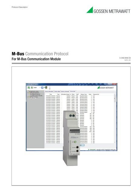
M-<strong>Bus</strong> <strong>Communication</strong> <strong>Protocol</strong><br />
For M-<strong>Bus</strong> <strong>Communication</strong> Module<br />
3-349-656-03<br />
1/11.11
Limitation of Liability<br />
The Manufacturer reserves the right to modify the specifications in this manual without previous warning. Any copy of this manual, in<br />
part or in full, whether by photocopy or by other means, even of electronic nature, without the manufacture giving written authorisation,<br />
breaches the terms of copyright and is liable to prosecution.<br />
It is absolutely forbidden to use the device for different uses other than those for which it has been devised for, as inferred to in this<br />
manual. When using the features in this device, obey all laws and respect privacy and legitimate rights of others.<br />
EXCEPT TO THE EXTENT PROHIBITED BY APPLICABLE LAW, UNDER NO CIRCUMSTANCES SHALL THE MANUFACTURER BE<br />
LIABLE FOR CONSEQUENTIAL DAMAGES SUSTAINED IN CONNECTION WITH SAID PRODUCT AND THE MANUFACTURER NEITHER<br />
ASSUMES NOR AUTHORIZES ANY REPRESENTATIVE OR OTHER PERSON TO ASSUME FOR IT ANY OBBLIGATION OR LIABILTY<br />
OTHER THAN SUCH AS IS EXPRESSLY SET FORTH HEREIN.<br />
All trademarks in this manual are property of their respective owners.<br />
The information contained in this manual is for information purposes only, is subject to changes without previous warning and cannot<br />
be considered binding for the Manufacturer. The Manufacturer assumes no responsabilty for any errors or incoherence possibly<br />
contained in this manual.<br />
Printed in Italy.
M-<strong>Bus</strong> communication protocol<br />
for M-BUS communication module<br />
July edition 2011
Index<br />
1. M-<strong>Bus</strong> interface.............................................................................. 9<br />
1.1 Overview..........................................................................................................................9<br />
2. Telegram formats........................................................................... 9<br />
2.1 Telegram fields................................................................................................................9<br />
2.1.1 C Field.................................................................................................................................10<br />
2.1.2 A Field.................................................................................................................................10<br />
2.1.3 CI Field................................................................................................................................10<br />
2.1.4 L Field..................................................................................................................................11<br />
2.1.5 CS Field (Checksum)...........................................................................................................11<br />
2.2 Active data.....................................................................................................................11<br />
2.2.1 Coding of Active Data Transmitted From Slave to Master: Fixed Data Record Header.......11<br />
2.2.2 Coding of Active Data Transmitted From Slave to Master: Data Records............................11<br />
2.2.2.1 Data Information Block (DIB)................................................................................................................12<br />
2.2.2.2 Value Information Block (VIB)..............................................................................................................12<br />
2.2.2.3 Standard Value Information Field (VIF) Used...................................................................................13<br />
2.2.2.4 Standard Value Information Field Extension (VIFE) Used.............................................................13<br />
2.2.2.5 Manufacturer Specific Value Information Field Extension (VIFE) Used...................................13<br />
3. <strong>Communication</strong> process............................................................... 15<br />
3.1 Send / confirm procedure..............................................................................................15<br />
3.1.1 SND_NKE............................................................................................................................15<br />
3.1.2 SND_UD...............................................................................................................................15<br />
3.1.2.1 Set Primary Address...............................................................................................................................16<br />
3.1.2.2 Set Secondary Address..........................................................................................................................17<br />
3.1.2.3 Set Baud Rate............................................................................................................................................18<br />
3.1.2.4 Reset Total/Tariff 1/Tariff 2/All Energy Counters.......................................................................19<br />
3.1.2.5 Reset Partial Energy Counters...........................................................................................................20
3.1.2.6 Start Partial Energy Counters...........................................................................................................22<br />
3.1.2.7 Stop Partial Energy Counters.............................................................................................................23<br />
3.1.2.8 Select a Slave Using Secondary Address.........................................................................................24<br />
3.1.2.9 Set Parameters Masks...........................................................................................................................25<br />
3.1.3 REQ_UD2.............................................................................................................................27<br />
3.1.4 RSP_UD...............................................................................................................................27<br />
3.1.4.1 3-Phase, Phase 1, Phase 2 and Phase 3 Imported Active Energy, Total.......................................28<br />
3.1.4.2 3-Phase, Phase 1, Phase 2 and Phase 3 Exported Active Energy, Total.......................................28<br />
3.1.4.3 3-Phase, Phase 1, Phase 2 and Phase 3 Imported Inductive Apparent Energy, Total..............29<br />
3.1.4.4 3-Phase, Phase 1, Phase 2 and Phase 3 Exported Inductive Apparent Energy, Total..............29<br />
3.1.4.5 3-Phase, Phase 1, Phase 2 and Phase 3 Imported Capacitive Apparent Energy, Total............29<br />
3.1.4.6 3-Phase, Phase 1, Phase 2 and Phase 3 Exported Capacitive Apparent Energy, Total............30<br />
3.1.4.7 3-Phase, Phase 1, Phase 2 and Phase 3 Imported Inductive Reactive Energy, Total................30<br />
3.1.4.9 3-Phase, Phase 1, Phase 2 and Phase 3 Imported Capacitive Reactive Energy, Total..............31<br />
3.1.4.10 3-Phase, Phase 1, Phase 2 and Phase 3 Exported Capacitive Reactive Energy, Total............31<br />
3.1.4.11 3-Phase, Phase 1, Phase 2 and Phase 3 Imported Active Energy, Tariff 1.................................32<br />
3.1.4.12 3-Phase, Phase 1, Phase 2 and Phase 3 Exported Active Energy, Tariff 1.................................32<br />
3.1.4.13 3-Phase, Phase 1, Phase 2 and Phase 3 Imported Inductive Apparent Energy, Tariff 1........32<br />
3.1.4.14 3-Phase, Phase 1, Phase 2 and Phase 3 Exported Inductive Apparent Energy, Tariff 1.......33<br />
3.1.4.15 3-Phase, Phase 1, Phase 2 and Phase 3 Imported Capacitive Apparent Energy, Tariff 1......33<br />
3.1.4.16 3-Phase, Phase 1, Phase 2 and Phase 3 Exported Capacitive Apparent Energy, Tariff 1......33<br />
3.1.4.17 3-Phase, Phase 1, Phase 2 and Phase 3 Imported Inductive Reactive Energy, Tariff 1..........34<br />
3.1.4.18 3-Phase, Phase 1, Phase 2 and Phase 3 Exported Inductive Reactive Energy, Tariff 1.........34<br />
3.1.4.19 3-Phase, Phase 1, Phase 2 and Phase 3 Imported Capacitive Reactive Energy, Tariff 1........34<br />
3.1.4.20 3-Phase, Phase 1, Phase 2 and Phase 3 Exported Capacitive Reactive Energy, Tariff 1........35<br />
3.1.4.21 3-Phase, Phase 1, Phase 2 and Phase 3 Imported Active Energy, Tariff 2.................................35<br />
3.1.4.22 3-Phase, Phase 1, Phase 2 and Phase 3 Exported Active Energy, Tariff 2.................................36<br />
3.1.4.23 3-Phase, Phase 1, Phase 2 and Phase 3 Imported Inductive Apparent Energy, Tariff 2........36<br />
3.1.4.24 3-Phase, Phase 1, Phase 2 and Phase 3 Exported Inductive Apparent Energy, Tariff 2.......36<br />
3.1.4.25 3-Phase, Phase 1, Phase 2 and Phase 3 Imported Capacitive Apparent Energy, Tariff 2......37<br />
3.1.4.26 3-Phase, Phase 1, Phase 2 and Phase 3 Exported Capacitive Apparent Energy, Tariff 2......37<br />
3.1.4.27 3-Phase, Phase 1, Phase 2 and Phase 3 Imported Inductive Reactive Energy, Tariff 2..........37<br />
3.1.4.28 3-Phase, Phase 1, Phase 2 and Phase 3 Exported Inductive Reactive Energy, Tariff 2.........38<br />
3.1.4.29 3-Phase, Phase 1, Phase 2 and Phase 3 Imported Capacitive Reactive Energy, Tariff 2........38<br />
3.1.4.30 3-Phase, Phase 1, Phase 2 and Phase 3 Exported Capacitive Reactive Energy, Tariff 2........39<br />
3.1.4.31 3-Phase, Phase 1, Phase 2 and Phase 3 Voltage...............................................................................39<br />
3.1.4.32 Line 12, Line 23 and Line 31 Voltage....................................................................................................39<br />
3.1.4.33 3-Phase, Phase 1, Phase 2, Phase 3 and Neutral Current............................................................40<br />
3.1.4.34 Frequency................................................................................................................................................40
3.1.4.35 Phase Order............................................................................................................................................40<br />
3.1.4.36 3-Phase, Phase 1, Phase 2 and Phase 3 Power Factor....................................................................40<br />
3.1.4.37 3-Phase, Phase 1, Phase 2 and Phase 3 Active Power.....................................................................41<br />
3.1.4.38 3-Phase, Phase 1, Phase 2 and Phase 3 Apparent Power...............................................................41<br />
3.1.4.39 3-Phase, Phase 1, Phase 2 and Phase 3 Reactive Power................................................................41<br />
3.1.4.40 3-Phase Imported and Exported Active Energy Partial..............................................................42<br />
3.1.4.41 3-Phase Imported and Exported Inductive Apparent Energy Partial.....................................42<br />
3.1.4.42 3-Phase Imported and Exported Capacitive Apparent Energy Partial....................................42<br />
3.1.4.43 3-Phase Imported and Exported Inductive Reactive Energy Partial.......................................43<br />
3.1.4.44 3-Phase Imported and Exported Capacitive Reactive Energy Partial......................................43<br />
3.1.4.45 3-Phase Active Energy Balance..........................................................................................................44<br />
3.1.4.46 3-Phase Inductive and Capacitive Apparent Energy Balance....................................................44<br />
3.1.4.47 3-Phase Inductive and Capacitive Reactive Energy Balance......................................................44<br />
3.1.4.48 CT Value....................................................................................................................................................45<br />
3.1.4.49 PT Value....................................................................................................................................................45<br />
3.1.4.50 Actual Tariff..........................................................................................................................................45<br />
3.1.4.51 Serial Number........................................................................................................................................45<br />
3.1.4.52 Model........................................................................................................................................................45<br />
3.1.4.53 Type............................................................................................................................................................46<br />
3.1.4.54 Energy Counter Firmware Release..................................................................................................46<br />
3.1.4.55 Energy Counter Hardware Release.................................................................................................46<br />
3.1.4.56 Primary or Secondary Value..............................................................................................................47<br />
3.1.4.57 Error Code..............................................................................................................................................47<br />
3.1.4.58 Out Of Range...........................................................................................................................................47<br />
3.1.4.59 Fabrication Number..............................................................................................................................48<br />
3.1.4.60 M-BUS Module Firmware Release......................................................................................................48<br />
3.1.4.61 M-BUS Module Hardware Release.....................................................................................................48<br />
3.1.4.62 Partial Counter Status........................................................................................................................48<br />
3.1.4.63 FSA Value..................................................................................................................................................48<br />
ANNEX A........................................................................................... 49<br />
ANNEX B.......................................................................................... 50<br />
ANNEX C........................................................................................... 52
1. M-<strong>Bus</strong> interface<br />
The M-BUS Interface (1 module wide, DIN rail mount) is developed to connect the Energy Counter to M-BUS.<br />
The interface receives the measurement data from the Energy Counter using infrared port available on the side of the counter, and<br />
gets the power supply from the bus.<br />
1.1 Overview<br />
• M-BUS Interface complying with EN13757-2 and EN13757-3<br />
• Circuiting by means of drilled two-wires cables<br />
• 2 screw clamps on M-BUS Interface<br />
• Current consumption of M-BUS Interface: ≤ 4 mA. This corresponds to 3 standard loads.<br />
• The data transmission speed is selectable between 300, 600, 1200, 2400, 4800, 9600, 115200 and 38400 baud<br />
• The default speed is 2400 baud<br />
• The default Primary Address is 000<br />
English<br />
2. Telegram formats<br />
The telegram formats are three, identified by the first character.<br />
Byte Single character (HEX) Short Telegram (HEX) Long Telegram (HEX)<br />
1 E5 10 68<br />
2 C Field L Field<br />
3 A Field L Field (Ripetition)<br />
4 CS (Checksum) 68<br />
5 16 C Field<br />
6 A Field<br />
7 CI Field<br />
8 - YY Data (0 – 246 Bytes)<br />
YY + 1<br />
CS (Checksum)<br />
YY + 2 16<br />
Table 2.1 – The M-BUS Telegram Formats<br />
• Single Character: This telegram format consists of the single character E5h and is used to acknowledge the telegram<br />
received.<br />
• Short Telegram: This telegram is identified by the start character 10h and consists of five character. It’s used by the M-BUS<br />
Master to command the transmission of data from the M-BUS Slave.<br />
• Long Telegram: This telegram is identified by the start character 68h and consists of a variable number of characters, in which<br />
are present also the active data. It’s used by the M-BUS Master to transmits commands to the M-BUS Slave, and by the M-BUS<br />
Slave to send the read-out Data from the M-BUS Master.<br />
2.1 Telegram fields<br />
The telegram fields (C, A, CI Fields, L and CS) have a fixed length of one byte (8 bit) and serve predetermined effects in the M-BUS<br />
communication. The L Field defines the number of bytes of the active data.<br />
M-<strong>Bus</strong> communication protocol 9
2.1.1 C Field<br />
The Control Field (C Field) contains information on the direction of the exchange of communication, the success of the actual<br />
operation of communication and the proper function of the telegram.<br />
English<br />
Bit Number 7 6 5 4 3 2 1 0<br />
Master > Slave 0 1 FCB FCV F3 F2 F1 F0<br />
Slave > Master 0 0 ACD DFC F3 F2 F1 F0<br />
Table 2.2 – C Field Bit Division<br />
The Bit Nr 6 is set to 1 if the communication has the direction Master > Slave; viceversa it is set to 0.<br />
In the Master > Slave direction, if the frame count bit valid (FCV - Bit Nr 4) is set to 1, then the frame count bit (FCB – Bit Nr 5) has<br />
not to be ignored.<br />
The FCB is used to indicate successful transmission procedure. A Master shall toggle the bit after a successful reception of a reply<br />
from the Slave. After this, if the Slave answer is multi-telegram, the Slave has to send the next telegram of the multi-telegram<br />
answer.<br />
If the expected reply is missing, or the reception faults, the master resends the same telegram with the same FCB.<br />
The Bits Nr 3 – 0 are the function code of the message.<br />
The C Field used here, are:<br />
Telegram Name C Field (BIN) C Field (HEX) Telegram Description<br />
SND_NKE 01000000 40 Short Frame Initialization of the Slave<br />
SND_UD 01x10011 53 / 73 Long Frame Master send data to Slave<br />
REQ_UD2 01x11011 5B / 7B Short Frame Master requests Class 2 Data to Slave<br />
RSP_UD 000x1000 08 / 18 Long Frame Data transfer from Slave to Master<br />
Table 2.3 – C Field of the commands used in this protocol<br />
2.1.2 A Field<br />
The Address Field (A Field) is used to address the recipient in the calling direction, and to identify the sender of information in the<br />
receiving direction.<br />
The size of this field is one byte, and it can assume the value between 0 – 255, divided in this way:<br />
A Field (HEX) Primary Address Remarks<br />
00 0 Default Address Given by Manufacturer<br />
01 – FA 1 – 250 Primary Address Settable<br />
FB, FC 251, 252 Reserved for Future Use<br />
FD 253 Used for Secondary Address Procedures<br />
FE 254 Use to Transmit Information to All Partecipants in the M-BUS System<br />
FF 255 Use to Transmit Information to All Partecipants in the M-BUS System<br />
Table 2.4 – Value of Address Field<br />
Using the address 254 (FEh) every Slave answer with the acknowledging (E5h) or with their primary address.<br />
Using the address 255 (FFh) no one Slave replies.<br />
2.1.3 CI Field<br />
The Control Information (CI Field) contains information for the receiver of the telegram.<br />
The CI Field values used here, are:<br />
CI Field (HEX)<br />
Primary Address<br />
51 The telegram contains data for the Slave<br />
52 Selection of the Slave<br />
72 The telegram contains data for the Master<br />
B8<br />
B9<br />
Set Baud Rate to 300 bps<br />
Set Baud Rate to 600 bps<br />
10 M-<strong>Bus</strong> communication protocol
Table 2.5 – Value of CI Field<br />
2.1.4 L Field<br />
CI Field (HEX)<br />
BA<br />
BB<br />
BC<br />
BD<br />
BE<br />
BF<br />
Primary Address<br />
Set Baud Rate to 1200 bps<br />
Set Baud Rate to 2400 bps<br />
Set Baud Rate to 4800 bps<br />
Set Baud Rate to 9600 bps<br />
Set Baud Rate to 19200 bps<br />
Set Baud Rate to 38400 bps<br />
The Length Field (L Field) defines the number of bytes (expressed in hex value) of the Active Data making up the telegram, plus 3<br />
byte for the C, A and Cl Fields.<br />
This field is always transmitted twice in Long Telegrams.<br />
English<br />
2.1.5 CS Field (Checksum)<br />
The Checksum (CS Field) serves to recognize transmission and synchronization faults, and is configured from specific parts of<br />
telegram. The checksum is calculated from the arithmetical sum of the data mentioned above plus the Active Data, i.e. from C Field<br />
to CS Field (excluded).<br />
2.2 Active data<br />
The Active Data (0 – 246 bytes) in Long Telegrams include the data to be read from the M-BUS Master (Read-Out Data), or Command<br />
Information transmitted by the Master to the Slave.<br />
2.2.1 Coding of Active Data Transmitted From Slave to Master: Fixed Data Record Header<br />
Each block of Active Data transmitted by the Slave to the Master starts with the following Fixed Data Record Header (FDH):<br />
Byte Nr. Size (Byte) Value (Hex) Description<br />
1 – 4 4 xx xx xx xx M-BUS Interface Identification Number<br />
5 – 6 2 xx xx Manufacturer’s ID<br />
7 1 xx Version Number of M-BUS Interface Firmware (00 – FF)<br />
8 1 02 Medium: Electricity<br />
9 1 xx Access Number (00 – FF > 00)<br />
10 1 xx<br />
M-BUS Interface Status (00 = Energy Counter Unreachable,<br />
01 = Energy Counter Reachable)<br />
11 – 12 2 0000 Signature (always 0000, i.e. not used)<br />
Table 2.6 – Fixed Data Record Header<br />
The Identification Number is a changeable number by the customer and runs from 00000000 to 99999999.<br />
The Access Number has unsigned binary coding, and is incremented (modulo 256) by one after each RSP_UD from the Slave.<br />
2.2.2 Coding of Active Data Transmitted From Slave to Master: Data Records<br />
Every Data Record sent by Slave to the Master consist of the following Data Record Header (DRH) :<br />
Data Information Block (DIB) Value Information Block (VIB)<br />
DIF DIFE VIF VIFE Data<br />
1 Byte 0 – 10 Byte(s) 1 Byte 0 – 10 Byte(s) 0 – n Bytes<br />
Table 2.7 – Data Records Structure<br />
M-<strong>Bus</strong> communication protocol 11
2.2.2.1 Data Information Block (DIB)<br />
The Data Information Block (DIB) contains as a minimum one Data Information Field (DIF). This byte can be extended by a further<br />
10 Data Information Field Extension Bytes (DIFE).<br />
The coding of DIF for this protocol is:<br />
English<br />
Bit Name Description<br />
7 Extension Bit<br />
Specifies if a DIFE Byte follows:<br />
0 = No<br />
1 = Yes<br />
6 LSB of Storage Number Always at 0, i.e. not used<br />
5 - 4 Functions Field<br />
3 - 0 Data Field<br />
Table 2.8 – Data Information Field Structure<br />
Specifies the kind of the value, always at:<br />
00 = Instantaneous Value<br />
Length and Coding of Data:<br />
0001: 8 Bit Integer<br />
0010: 16 Bit Integer<br />
0011: 24 Bit Integer<br />
0100: 32 Bit Integer<br />
0110: 48 Bit Integer<br />
0111: 64 Bit Integer<br />
1100: 8 digit BCD<br />
1101: Variable Length<br />
The coding of DIFE for this protocol is:<br />
Bit Name Description<br />
7 Extension Bit<br />
6 Unit<br />
5 - 4 Tariff<br />
3 - 0 Storage Number Always at 0000<br />
Table 2.9 – Data Information Field Extension Structure<br />
Specifies if a DIFE Byte follows:<br />
0 = No<br />
1 = Yes<br />
Specifies the kind of Energy or Power when Bit 7 is set to 1:<br />
0 = Reactive<br />
1 = Apparent<br />
Specifies which tariff the values are related:<br />
00 = Total Value<br />
01 = Tariff 1<br />
02 = Tariff 2<br />
If Bit 7 is set to 0, the following Data Byte are related to Active Energy or Power. So, if the first DIFE is followed by another DIFE (i.e.<br />
Bit 7 is set to 1), the following Data Byte are related to Reactive or Apparent Energy or Power, depending on Bit 6 value.<br />
2.2.2.2 Value Information Block (VIB)<br />
The Value Information Block (VIB) contains as a minimum one Value Information Field (VIF). This byte can be extended by a further<br />
10 Value Information Field Extension Bytes (DIFE).<br />
The coding of VIF is:<br />
Bit Name Description<br />
7 Extension Bit<br />
6 - 0 Value Information<br />
Table 2.10 – Value Information Field Structure<br />
Specifies if a VIFE Byte follows:<br />
0 = No<br />
1 = Yes<br />
Contains Information on the single Value, such as Unit,<br />
Multiplicator, etc…<br />
12 M-<strong>Bus</strong> communication protocol
The coding of VIFE is:<br />
Bit Name Description<br />
7 Extension Bit<br />
6 - 0 Value Information<br />
Table 2.11 – Value Information Field Extension Structure<br />
2.2.2.3 Standard Value Information Field (VIF) Used<br />
Specifies if a VIFE Byte follows:<br />
0 = No<br />
1 = Yes<br />
Contains Information on the single Value, such as Unit,<br />
Multiplicator, etc…<br />
English<br />
VIFE (BIN) VIFE (HEX) Description Unit<br />
10000010 82 Energy 0.1Wh<br />
01111001 79 Set Secondary Address Dimensionless<br />
01111010 7A Set Primary Address Dimensionless<br />
10101000 A8 Power mW<br />
11111101 FD A standard VIFE from extension table follows Dimensionless<br />
11111111 FF A further manufacturer specific VIFE follows Dimensionless<br />
Table 2.12 – Standard Value Information Field Used<br />
2.2.2.4 Standard Value Information Field Extension (VIFE) Used<br />
VIF (BIN) VIF (HEX) Description Unit<br />
00001011 0B Parameter Set Identification Dimensionless<br />
00001100 0C Firmware Version Dimensionless<br />
00001101 0D Hardware Version Dimensionless<br />
11001100 CC Voltage mV<br />
11011001 D9 Current mA<br />
Table 2.13– Standard Value Information Field Extension Used<br />
2.2.2.5 Manufacturer Specific Value Information Field Extension (VIFE) Used<br />
VIFE (BIN) VIFE (HEX) Description Unit<br />
00000000 00 3-Phase 0.1Wh, mV, mA, mW, mVA or mvar<br />
00000001 01 Phase 1 0.1Wh, mV, mA, mW, mVA or mvar<br />
00000010 02 Phase 2 0.1Wh, mV, mA, mW, mVA or mvar<br />
00000011 03 Phase 3 0.1Wh, mV, mA, mW, mVA or mvar<br />
00000100 04 Neutral mA<br />
00000101 05 Line 12 mV<br />
00000110 06 Line 23 mV<br />
00000111 07 Line 31 mV<br />
00010000 10 3-Phase Imported Inductive Energy 0.1VAh or 0.1varh<br />
00010001 11 Phase 1 Imported Inductive Energy 0.1VAh or 0.1varh<br />
00010010 12 Phase 2 Imported Inductive Energy 0.1VAh or 0.1varh<br />
00010011 13 Phase 3 Imported Inductive Energy 0.1VAh or 0.1varh<br />
00100000 20 3-Phase Exported Inductive Energy 0.1VAh or 0.1varh<br />
00010001 21 Phase 1 Exported Inductive Energy 0.1VAh or 0.1varh<br />
00010010 22 Phase 2 Exported Inductive Energy 0.1VAh or 0.1varh<br />
M-<strong>Bus</strong> communication protocol 13
English<br />
VIFE (BIN) VIFE (HEX) Description Unit<br />
00010011 23 Phase 3 Exported Inductive Energy 0.1VAh or 0.1varh<br />
00100100 24 3-Phase Inductive Energy 0.1VAh or 0.1varh<br />
00110000 30 3-Phase Imported Capacitive Energy 0.1VAh or 0.1varh<br />
00110001 31 Phase 1 Imported Capacitive Energy 0.1VAh or 0.1varh<br />
00110010 32 Phase 2 Imported Capacitive Energy 0.1VAh or 0.1varh<br />
00110011 33 Phase 3 Imported Capacitive Energy 0.1VAh or 0.1varh<br />
01000000 40 3-Phase Exported Capacitive Energy 0.1VAh or 0.1varh<br />
01000001 41 Phase 1 Exported Capacitive Energy 0.1VAh or 0.1varh<br />
01000010 42 Phase 2 Exported Capacitive Energy 0.1VAh or 0.1varh<br />
01000011 43 Phase 3 Exported Capacitive Energy 0.1VAh or 0.1varh<br />
01000100 44 3-Phase Capacitive Energy 0.1VAh or 0.1varh<br />
01010000 50 Frequency mHz<br />
01010001 51 Phase Order Dimensionless<br />
01010010 52 CT Value Dimensionless<br />
01010011 53 PT Value Dimensionless<br />
01010100 54 Actual Tariff Dimensionless<br />
01010101 55 Serial Number Dimensionless<br />
01010110 56 Model Dimensionless<br />
01010111 57 Type Dimensionless<br />
01011000 58 Firmware Release Dimensionless<br />
01011001 59 Hardware Release Dimensionless<br />
01100000 60 Wiring Mode Dimensionless<br />
01100001 61 Primary or Secondary Value Dimensionless<br />
01100010 62 Error Code Dimensionless<br />
01100011 63 Out Of Range Dimensionless<br />
01100100 64 FSA Value A<br />
01110000 70 Reset Counter Dimensionless<br />
01110001 71 Start Counter Dimensionless<br />
01110010 72 Stop Counter Dimensionless<br />
01110011 73 Partial Counter Status Dimensionless<br />
10000000 80 Imported Energy 0.1Wh<br />
10000001 81 Exported Energy 0.1Wh<br />
10000010 82 Partial Dimensionless<br />
10000011 83 Balance Dimensionless<br />
10000100 84 Power Factor Dimensionless<br />
10010000 90 Unit Volt-Ampere * 10 -3 mVA<br />
10010001 91 Unit Volt-Ampere per hour * 10 -1 0.1VAh<br />
10010010 92 Unit Reactive Volt-Ampere * 10 -3 mvar<br />
10010011 93 Unit Reactive Volt-Ampere per hour * 10 -1 0.1varh<br />
10010100 94 Unit Hertz (cycle per second) * 10 -3 MHz<br />
Table 2.14 –Manufacturer Specific Value Information Field Extension Used<br />
If Bit No. 7 in the Specific Value Information Field Extension (VIFE) is set to 1, another VIFE Byte follows.<br />
If Bit 7 is set to 0, the first Data Byte follows next.<br />
14 M-<strong>Bus</strong> communication protocol
3. <strong>Communication</strong> process<br />
The M-BUS module accepts two kinds of transmission:<br />
Send / Confirm > SND / CON<br />
Request / Respond > REQ / RSP<br />
A standard straight communication between M-BUS Master and M-BUS Slave is:<br />
MASTER<br />
SLAVE<br />
English<br />
SND_NKE > E5h<br />
SND_UD > E5h<br />
REQ_UD2 > RSP_UD<br />
3.1 Send / confirm procedure<br />
3.1.1 SND_NKE<br />
This procedure serve to start up after an interruption or beginning of communication. If the Slave was selected for secondary<br />
addressing, it will be deselected.<br />
The value of the frame count bit FCB is cleared in the Slave, i.e. it expects that the first telegram from a Master with FCV = 1, has<br />
the FCB = 1.<br />
The Slave confirms a correct reception of the telegram with the single character acknowledge (E5h) or omits the answer if it didn’t<br />
receive the telegram correctly.<br />
Here follows the structure of SND_NKE command:<br />
Byte Nr. Size (Byte) Value (HEX) Description<br />
1 1 10 Start character - short telegram<br />
2 1 40 C Field<br />
3 1 xx<br />
4 1 xx<br />
A Field – Primary Address<br />
5 1 16 Stop charcater<br />
Table 3.1 – SND_NKE command Structure<br />
00 – FA: Valid Primary Address<br />
FB, FC: Reserved for Future Use<br />
FD: Transmission is by Secondary Address<br />
FE: Transmission to All M-BUS Slave in the System (everyone<br />
sends E5h)<br />
FF: Transmission to All M-BUS Slave in the System (no one sends<br />
E5h)<br />
CS Checksum, summed from C-Field to Selected Parameter of<br />
Parameter Set 19 (byte 2 > byte 4)<br />
Answer of the Slave: E5h<br />
3.1.2 SND_UD<br />
This procedure is used to send user data to the M-BUS Slave. The Slave confirms a correct reception of the telegram with the single<br />
character acknowledge (E5h) or omits the answer if it didn’t receive the telegram correctly.<br />
Here follows the structure of the SND_UD commands used in this protocol.<br />
M-<strong>Bus</strong> communication protocol 15
3.1.2.1 Set Primary Address<br />
This action enables to set a new Primary Address in the Slave interface.<br />
Here follows the command, using the Primary Address of the Slave:<br />
English<br />
Byte Nr. Size (Byte) Value (HEX) Description<br />
1 1 68 Start character long query<br />
2 1 06 L-Field<br />
3 1 06 L-Field Ripetition<br />
4 1 68 Start character long query ripetition<br />
5 1 73 C-Field SND_UD<br />
6 1 xx A-Field, Primary Address (00-FF = 0-255)<br />
7 1 51 CI-Field<br />
8 1 01 DIF: 8 Bit Integer, 1 Byte<br />
9 1 7A VIF: Set Primary Address<br />
10 1 xx<br />
11 1 xx<br />
Value: New Primary Address<br />
Valid Range: 00 – FA (0 - 250)<br />
Invalid Range: FB – FF<br />
12 1 16 Stop character<br />
Table 3.2 – SND_UD command: Set Primary Address Using Primary Address<br />
CS Checksum, summed from C-Field to Selected Parameter of<br />
Parameter Set 19 (byte 5 > byte 10)<br />
Here follows the command, using the Secondary Address of the Slave:<br />
Byte Nr. Size (Byte) Value (HEX) Description<br />
1 1 68 Start character long query<br />
2 1 0E L-Field<br />
3 1 0E L-Field Ripetition<br />
4 1 68 Start character long query ripetition<br />
5 1 73 C-Field SND_UD<br />
6 1 FD A-Field, Primary Address = 253, i.e. take the secondary address<br />
7 1 51 CI-Field<br />
8 – 15 8<br />
xx xx xx xx<br />
xx xx xx xx<br />
Secondary Address<br />
16 1 01 DIF: 8 Bit Integer, 1 Byte<br />
17 1 7A VIF: Set Primary Address<br />
18 1 xx<br />
19 1 xx<br />
Value: New Primary Address<br />
Valid Range: 00 – FA (0 - 250)<br />
Invalid Range: FB – FF<br />
20 1 16 Stop character<br />
Table 3.3 – SND_UD command: Set Primary Address Using Secondary Address<br />
CS Checksum, summed from C-Field to Selected Parameter of<br />
Parameter Set 19 (byte 5 > byte 18)<br />
Answer of the Slave: E5h<br />
16 M-<strong>Bus</strong> communication protocol
3.1.2.2 Set Secondary Address<br />
This action enables to set a new Secondary Address in the Slave interface.<br />
The Secondary Address has this structure:<br />
Byte Nr. Size (Byte) Value (HEX) Description<br />
1 – 4 4 xx xx xx xx<br />
Identification Number<br />
Range : 00000000 - 99999999<br />
5 – 6 2 xx xx<br />
Manufacturer ID<br />
Range: 01 – FF, 01 - FF<br />
7 1 xx<br />
Version Number<br />
Range: 01 - FF<br />
8 1 02<br />
Device Type Identification<br />
02: Electricity<br />
Table 3.4 – Secondary Address Structure<br />
English<br />
Here follows the command, using the Primary Address of the Slave:<br />
Byte Nr. Size (Byte) Value (HEX) Description<br />
1 1 68 Start character long query<br />
2 1 09 L-Field<br />
3 1 09 L-Field Ripetition<br />
4 1 68 Start character long query ripetition<br />
5 1 73 C-Field SND_UD<br />
6 1 xx A-Field, Primary Address (00-FF = 0-255)<br />
7 1 51 CI-Field<br />
8 1 0C DIF: 8 digits BCD, 4 Byte<br />
9 1 79 VIF: Set Secondary Address<br />
10 1 xx<br />
11 1 xx<br />
12 1 xx<br />
13 1 xx<br />
14 1 xx<br />
Value: New Secondary Address digit 7 and 8<br />
Range: 00 - 99<br />
Value: New Secondary Address digit 5 and 6<br />
Range: 00 – 99<br />
Value: New Secondary Address digit 3 and 4<br />
Range: 00 – 99<br />
Value: New Secondary Address digit 1 and 2<br />
Range: 00 - 99<br />
15 1 16 Stop character<br />
Table 3.5 – SND_UD command: Set Secondary Address Using Primary Address<br />
CS Checksum, summed from C-Field to Selected Parameter of<br />
Parameter Set 19 (byte 5 > byte 13)<br />
Here follows the command, using the Secondary Address of the Slave:<br />
Byte Nr. Size (Byte) Value (HEX) Description<br />
1 1 68 Start character long query<br />
2 1 11 L-Field<br />
3 1 11 L-Field Ripetition<br />
4 1 68 Start character long query ripetition<br />
5 1 73 C-Field SND_UD<br />
6 1 FD A-Field, Primary Address = 253, i.e. take the secondary address<br />
7 1 51 CI-Field<br />
M-<strong>Bus</strong> communication protocol 17
English<br />
Byte Nr. Size (Byte) Value (HEX) Description<br />
8 – 15 8<br />
xx xx xx xx<br />
xx xx xx xx<br />
Secondary Address<br />
16 1 0C DIF: 8 digits BCD, 4 Byte<br />
17 1 79 VIF: Set Secondary Address<br />
18 1 xx<br />
19 1 xx<br />
20 1 xx<br />
21 1 xx<br />
22 1 xx<br />
Value: New Secondary Address digit 7 and 8<br />
Range: 00 - 99<br />
Value: New Secondary Address digit 5 and 6<br />
Range: 00 – 99<br />
Value: New Secondary Address digit 3 and 4<br />
Range: 00 – 99<br />
Value: New Secondary Address digit 1 and 2<br />
Range: 00 - 99<br />
23 1 16 Stop character<br />
CS Checksum, summed from C-Field to Selected Parameter of<br />
Parameter Set 19 (byte 5 > byte 21)<br />
Table 3.6 – SND_UD command: Set Secondary Address Using Secondary Address<br />
Answer of the Slave: E5h<br />
3.1.2.3 Set Baud Rate<br />
This action allows to change the Baud Rate of the M-BUS Slave.<br />
The Slave answers with single character acknowledgement (E5h) in the old baud rate. As soon as the ACK is transmitted, the Slave<br />
switches to the new baud rate.<br />
To make sure that the Slave has properly changed its baud rate, the Master, within 2 minutes has to send a command to the Slave<br />
in the new baud rate. If the Slave doesn’t send the ACK after x retry, the Master has to return to the old baud rate.<br />
Here follows the command, using the Primary Address of the Slave:<br />
Byte Nr. Size (Byte) Value (HEX) Description<br />
1 1 68 Start character long query<br />
2 1 03 L-Field<br />
3 1 03 L-Field Ripetition<br />
4 1 68 Start character long query ripetition<br />
5 1 73 C-Field SND_UD<br />
6 1 xx A-Field, Primary Address (00 - FF = 0 - 255)<br />
7 1 xx<br />
8 1 xx<br />
CI-Field: Set New Baud Rate<br />
9 1 16 Stop character<br />
Table 3.7 – SND_UD command: Set Baud Rate Using Primary Address<br />
B8: Set Baud Rate to 300 baud<br />
B9: Set Baud Rate to 600 baud<br />
BA: Set Baud Rate to 1200 baud<br />
BB: Set Baud Rate to 2400 baud<br />
BC: Set Baud Rate to 4800 baud<br />
BD: Set Baud Rate to 9600 baud<br />
BE: Set Baud Rate to 19200 baud<br />
BF: Set Baud Rate to 38400 baud<br />
CS Checksum, summed from C-Field to Selected Parameter of<br />
Parameter Set 19 (byte 5 > byte 7)<br />
18 M-<strong>Bus</strong> communication protocol
Here follows the command, using the Secondary Address of the Slave:<br />
Byte Nr. Size (Byte) Value (HEX) Description<br />
1 1 68 Start character long query<br />
2 1 0B L-Field<br />
3 1 0B L-Field Ripetition<br />
4 1 68 Start character long query ripetition<br />
5 1 73 C-Field SND_UD<br />
6 1 FD A-Field, Primary Address = 253, i.e. take the secondary address<br />
7 1 xx<br />
8 – 15 8<br />
xx xx xx xx<br />
xx xx xx xx<br />
16 1 xx<br />
CI-Field: Set New Baud Rate<br />
B8: Set Baud Rate to 300 baud<br />
B9: Set Baud Rate to 600 baud<br />
BA: Set Baud Rate to 1200 baud<br />
BB: Set Baud Rate to 2400 baud<br />
BC: Set Baud Rate to 4800 baud<br />
BD: Set Baud Rate to 9600 baud<br />
BE: Set Baud Rate to 19200 baud<br />
BF: Set Baud Rate to 38400 baud<br />
Secondary Address<br />
17 1 16 Stop character<br />
CS Checksum, summed from C-Field to Selected Parameter of<br />
Parameter Set 19 (byte 5 > byte 15)<br />
English<br />
Table 3.8 – SND_UD command: Set Baud Rate Using Secondary Address<br />
Answer of the Slave: E5h<br />
3.1.2.4 Reset Total/Tariff 1/Tariff 2/All Energy Counters<br />
This action is permitted only if the Energy Counters is “NO MID” or “yes reset” type.<br />
Here follows the command, using the Primary Address of the Slave:<br />
Byte Nr. Size (Byte) Value (HEX) Description<br />
1 1 68 Start character long query<br />
2 1 07 L-Field<br />
3 1 07 L-Field Ripetition<br />
4 1 68 Start character long query ripetition<br />
5 1 73 C-Field SND_UD<br />
6 1 xx A-Field, Primary Address (00-FF = 0-255)<br />
7 1 51 CI-Field<br />
8 1 01 DIF: 8 Bit Integer, 1 Byte<br />
9 1 FF VIF followed by manufacturer specific VIFE<br />
10 1 70 manufacturer specific VIFE: Reset Counter<br />
11 1 xx<br />
12 1 xx<br />
13 1 16 Stop character<br />
Value: Kind of Energy Counters<br />
00: Reset Total Energy Counters<br />
01: Reset Tariff 1 Energy Counters<br />
02: Reset Tariff 2 Energy Counters<br />
03: Reset ALL Energy Counters<br />
Table 3.9 – SND_UD command: Reset Active Energy Counters Using Primary Address<br />
CS Checksum, summed from C-Field to Selected Parameter of<br />
Parameter Set 19 (byte 5 > byte 11)<br />
M-<strong>Bus</strong> communication protocol 19
Here follows the command, using the Secondary Address of the Slave:<br />
English<br />
Byte Nr. Size (Byte) Value (HEX) Description<br />
1 1 68 Start character long query<br />
2 1 0F L-Field<br />
3 1 0F L-Field Ripetition<br />
4 1 68 Start character long query ripetition<br />
5 1 73 C-Field SND_UD<br />
6 1 FD A-Field, Primary Address = 253, i.e. take the secondary address<br />
7 1 51 CI-Field<br />
8 – 15 8<br />
xx xx xx xx<br />
xx xx xx xx<br />
Secondary Address<br />
16 1 01 DIF: 8 Bit Integer, 1 Byte<br />
17 1 FF VIF followed by manufacturer specific VIFE<br />
18 1 70 Manufacturer specific VIFE: Reset Counter<br />
19 1 xx<br />
20 1 xx<br />
21 1 16 Stop character<br />
Value: Kind of Energy Counters<br />
00: Reset Total Energy Counters<br />
01: Reset Tariff 1 Energy Counters<br />
02: Reset Tariff 2 Energy Counters<br />
03: Reset ALL Energy Counters<br />
CS Checksum, summed from C-Field to Selected Parameter of<br />
Parameter Set 19 (byte 5 > byte 19)<br />
Table 3.10 – SND_UD command: Reset Active Energy Counters Using Secondary Address<br />
Answer of the Slave: E5h<br />
3.1.2.5 Reset Partial Energy Counters<br />
Here follows the command, using the Primary Address of the Slave:<br />
Byte Nr. Size (Byte) Value (HEX) Description<br />
1 1 68 Start character long query<br />
2 1 09 L-Field<br />
3 1 09 L-Field Ripetition<br />
4 1 68 Start character long query ripetition<br />
5 1 73 C-Field SND_UD<br />
6 1 xx A-Field, Primary Address (00-FF = 0-255)<br />
7 1 51 CI-Field<br />
8 1 01 DIF: 8 Bit Integer, 1 Byte<br />
9 1 FF VIF followed by manufacturer specific VIFE<br />
10 1 82 VIFE: Partial Counters<br />
11 1 FF VIFE followed by 3E specific VIFE<br />
12 1 70 Manufacturer specific VIFE: Reset Counter<br />
20 M-<strong>Bus</strong> communication protocol
Byte Nr. Size (Byte) Value (HEX) Description<br />
13 1 xx<br />
14 1 xx<br />
Value: Kind of Energy<br />
00: Imported Active Energy<br />
01: Exported Active Energy<br />
02: Imported Inductive Apparent Energy<br />
03: Exported Inductive Apparent Energy<br />
04: Imported Capacitive Apparent Energy<br />
05: Exported Capacitive Apparent Energy<br />
06: Imported Inductive Reactive Energy<br />
07: Exported Inductive Reactive Energy<br />
08: Imported Capacitive Reactive Energy<br />
09: Exported Capacitive Reactive Energy<br />
0A: ALL partial counters<br />
15 1 16 Stop character<br />
CS Checksum, summed from C-Field to Selected Parameter of<br />
Parameter Set 19 (byte 5 > byte 13)<br />
English<br />
Table 3.11 – SND_UD command: Reset Partial Energy Counter Using Primary Address<br />
Here follows the command, using the Secondary Address of the Slave:<br />
Byte Nr. Size (Byte) Value (HEX) Description<br />
1 1 68 Start character long query<br />
2 1 11 L-Field<br />
3 1 11 L-Field Ripetition<br />
4 1 68 Start character long query ripetition<br />
5 1 73 C-Field SND_UD<br />
6 1 FD A-Field, Primary Address = 253, i.e. take the secondary address<br />
7 1 51 CI-Field<br />
8 – 15 8<br />
xx xx xx xx<br />
xx xx xx xx<br />
16 1 01 DIF: 8 Bit Integer, 1 Byte<br />
Secondary Address UD (See the relative paragraph)<br />
17 1 FF VIF followed by manufacturer specific VIFE<br />
18 1 82 VIFE: Partial Counters<br />
19 1 FF VIFE followed by manufacturer specific VIFE<br />
20 1 70 VIFE: Reset Counters<br />
21 1 xx<br />
22 1 xx<br />
Value: Kind of Energy<br />
00: Imported Active Energy<br />
01: Exported Active Energy<br />
02: Imported Inductive Apparent Energy<br />
03: Exported Inductive Apparent Energy<br />
04: Imported Capacitive Apparent Energy<br />
05: Exported Capacitive Apparent Energy<br />
06: Imported Inductive Reactive Energy<br />
07: Exported Inductive Reactive Energy<br />
08: Imported Capacitive Reactive Energy<br />
09: Exported Capacitive Reactive Energy<br />
0A: ALL partial counters<br />
23 1 16 Stop character<br />
Table 3.12 – SND_UD command: Reset Partial Energy Counter Using Secondary Address<br />
CS Checksum, summed from C-Field to Selected Parameter of<br />
Parameter Set 19 (byte 5 > byte 21)<br />
Answer of the Slave: E5h<br />
M-<strong>Bus</strong> communication protocol 21
3.1.2.6 Start Partial Energy Counters<br />
Here follows the command, using the Primary Address of the Slave:<br />
English<br />
Byte Nr. Size (Byte) Value (HEX) Description<br />
1 1 68 Start character long query<br />
2 1 09 L-Field<br />
3 1 09 L-Field Ripetition<br />
4 1 68 Start character long query ripetition<br />
5 1 73 C-Field SND_UD<br />
6 1 xx A-Field, Primary Address (00-FF = 0-255)<br />
7 1 51 CI-Field<br />
8 1 01 DIF: 8 Bit Integer, 1 Byte<br />
9 1 FF VIF followed by manufacturer specific VIFE<br />
10 1 82 VIFE: Partial Counters<br />
11 1 FF VIFE followed by 3E specific VIFE<br />
12 1 71 Manufacturer specific VIFE: Start Counter<br />
13 1 xx<br />
14 1 xx<br />
Value: Kind of Energy<br />
00: Imported Active Energy<br />
01: Exported Active Energy<br />
02: Imported Inductive Apparent Energy<br />
03: Exported Inductive Apparent Energy<br />
04: Imported Capacitive Apparent Energy<br />
05: Exported Capacitive Apparent Energy<br />
06: Imported Inductive Reactive Energy<br />
07: Exported Inductive Reactive Energy<br />
08: Imported Capacitive Reactive Energy<br />
09: Exported Capacitive Reactive Energy<br />
0A: ALL partial counters<br />
15 1 16 Stop character<br />
CS Checksum, summed from C-Field to Selected Parameter of<br />
Parameter Set 19 (byte 5 > byte 13)<br />
Table 3.13 – SND_UD command: Start Partial Energy Counter Using Primary Address<br />
Here follows the command, using the Secondary Address of the Slave:<br />
Byte Nr. Size (Byte) Value (HEX) Description<br />
1 1 68 Start character long query<br />
2 1 11 L-Field<br />
3 1 11 L-Field Ripetition<br />
4 1 68 Start character long query ripetition<br />
5 1 73 C-Field SND_UD<br />
6 1 FD A-Field, Primary Address = 253, i.e. take the secondary address<br />
7 1 51 CI-Field<br />
8 – 15 8<br />
xx xx xx xx<br />
xx xx xx xx<br />
Secondary Address UD (See the relative paragraph)<br />
16 1 01 DIF: 8 Bit Integer, 1 Byte<br />
17 1 FF VIF followed by manufacturer specific VIFE<br />
18 1 82 VIFE: Partial Counters<br />
19 1 FF VIFE followed by manufacturer specific VIFE<br />
20 1 71 VIFE: Start Counters<br />
22 M-<strong>Bus</strong> communication protocol
Byte Nr. Size (Byte) Value (HEX) Description<br />
21 1 xx<br />
22 1 xx<br />
Value: Kind of Energy<br />
00: Imported Active Energy<br />
01: Exported Active Energy<br />
02: Imported Inductive Apparent Energy<br />
03: Exported Inductive Apparent Energy<br />
04: Imported Capacitive Apparent Energy<br />
05: Exported Capacitive Apparent Energy<br />
06: Imported Inductive Reactive Energy<br />
07: Exported Inductive Reactive Energy<br />
08: Imported Capacitive Reactive Energy<br />
09: Exported Capacitive Reactive Energy<br />
0A: ALL partial counters<br />
23 1 16 Stop character<br />
CS Checksum, summed from C-Field to Selected Parameter of<br />
Parameter Set 19 (byte 5 > byte 21)<br />
English<br />
Table 3.14 – SND_UD command: Start Partial Energy Counter Using Secondary Address<br />
Answer of the Slave: E5h<br />
3.1.2.7 Stop Partial Energy Counters<br />
Here follows the command, using the Primary Address of the Slave:<br />
Byte Nr. Size (Byte) Value (HEX) Description<br />
1 1 68 Start character long query<br />
2 1 09 L-Field<br />
3 1 09 L-Field Ripetition<br />
4 1 68 Start character long query ripetition<br />
5 1 73 C-Field SND_UD<br />
6 1 xx A-Field, Primary Address (00-FF = 0-255)<br />
7 1 51 CI-Field<br />
8 1 01 DIF: 8 Bit Integer, 1 Byte<br />
9 1 FF VIF followed by manufacturer specific VIFE<br />
10 1 82 VIFE: Partial Counters<br />
11 1 FF VIFE followed by 3E specific VIFE<br />
12 1 72 Manufacturer specific VIFE: Stop Counter<br />
13 1 xx<br />
14 1 xx<br />
Value: Kind of Energy<br />
00: Imported Active Energy<br />
01: Exported Active Energy<br />
02: Imported Inductive Apparent Energy<br />
03: Exported Inductive Apparent Energy<br />
04: Imported Capacitive Apparent Energy<br />
05: Exported Capacitive Apparent Energy<br />
06: Imported Inductive Reactive Energy<br />
07: Exported Inductive Reactive Energy<br />
08: Imported Capacitive Reactive Energy<br />
09: Exported Capacitive Reactive Energy<br />
0A: ALL partial counters<br />
15 1 16 Stop character<br />
Table 3.15 – SND_UD command: Stop Partial Energy Counter Using Primary Address<br />
CS Checksum, summed from C-Field to Selected Parameter of<br />
Parameter Set 19 (byte 5 > byte 13)<br />
M-<strong>Bus</strong> communication protocol 23
Here follows the command, using the Secondary Address of the Slave:<br />
English<br />
Byte Nr. Size (Byte) Value (HEX) Description<br />
1 1 68 Start character long query<br />
2 1 11 L-Field<br />
3 1 11 L-Field Ripetition<br />
4 1 68 Start character long query ripetition<br />
5 1 73 C-Field SND_UD<br />
6 1 FD A-Field, Primary Address = 253, i.e. take the secondary address<br />
7 1 51 CI-Field<br />
8 – 15 8<br />
xx xx xx xx<br />
xx xx xx xx<br />
16 1 01 DIF: 8 Bit Integer, 1 Byte<br />
Secondary Address UD (See the relative paragraph)<br />
17 1 FF VIF followed by manufacturer specific VIFE<br />
18 1 82 VIFE: Partial Counters<br />
19 1 FF VIFE followed by manufacturer specific VIFE<br />
20 1 72 VIFE: Stop Counters<br />
21 1 xx<br />
22 1 xx<br />
Value: Kind of Energy<br />
00: Imported Active Energy<br />
01: Exported Active Energy<br />
02: Imported Inductive Apparent Energy<br />
03: Exported Inductive Apparent Energy<br />
04: Imported Capacitive Apparent Energy<br />
05: Exported Capacitive Apparent Energy<br />
06: Imported Inductive Reactive Energy<br />
07: Exported Inductive Reactive Energy<br />
08: Imported Capacitive Reactive Energy<br />
09: Exported Capacitive Reactive Energy<br />
0A: ALL partial counters<br />
23 1 16 Stop character<br />
CS Checksum, summed from C-Field to Selected Parameter of<br />
Parameter Set 19 (byte 5 > byte 21)<br />
Table 3.16 – SND_UD command: Stop Partial Energy Counter Using Secondary Address<br />
Answer of the Slave: E5h<br />
3.1.2.8 Select a Slave Using Secondary Address<br />
Here follows the command to select a Slave by Secondary Address:<br />
Byte Nr. Size (Byte) Value (HEX) Description<br />
1 1 68 Start character long query<br />
2 1 0B L-Field<br />
3 1 0B L-Field Ripetition<br />
4 1 68 Start character long query ripetition<br />
5 1 73 C-Field SND_UD<br />
6 1 FD A-Field, Primary Address = 253, i.e. take the secondary address<br />
7 1 52 CI-Field<br />
8 – 15 8<br />
xx xx xx xx<br />
xx xx xx xx<br />
Secondary Address UD (See the relative paragraph)<br />
24 M-<strong>Bus</strong> communication protocol
Byte Nr. Size (Byte) Value (HEX) Description<br />
16 1 xx<br />
17 1 16 Stop character<br />
Table 3.17 – SND_UD command: Select a slave Using Secondary Address<br />
CS Checksum, summed from C-Field to Selected Parameter of<br />
Parameter Set 19 (byte 5 > byte 15)<br />
Answer of the Slave: E5h<br />
3.1.2.9 Set Parameters Masks<br />
This action allows to select the data to read-out from the Slave.<br />
It can be possible read-out all data, choose the desired data or choose a default mask that include various kind of data.<br />
English<br />
Read-Out All Data<br />
Here follows the command, using the Primary Address of the Slave:<br />
Byte Nr. Size (Byte) Value (HEX) Description<br />
1 1 68 Start character long query<br />
2 1 04 L-Field<br />
3 1 04 L-Field Ripetition<br />
4 1 68 Start character long query ripetition<br />
5 1 73 C-Field SND_UD<br />
6 1 xx A-Field, Primary Address (00-FF = 0-255)<br />
7 1 51 CI-Field<br />
8 1 7F DIF: Global Readout Request<br />
9 1 xx<br />
10 1 16 Stop character<br />
Table 3.18 – SND_UD command: Set Read-Out All Data Parameter Mask Using Primary Address<br />
CS Checksum, summed from C-Field to Selected Parameter of<br />
Parameter Set 19 (byte 5 > byte 8)<br />
Here follows the command, using the Secondary Address of the Slave:<br />
Byte Nr. Size (Byte) Value (HEX) Description<br />
1 1 68 Start character long query<br />
2 1 0C L-Field<br />
3 1 0C L-Field Ripetition<br />
4 1 68 Start character long query ripetition<br />
5 1 73 C-Field SND_UD<br />
6 1 FD A-Field, Primary Address = 253, i.e. take the secondary address<br />
7 1 51 CI-Field<br />
8 – 15 8<br />
xx xx xx xx<br />
xx xx xx xx<br />
Secondary Address<br />
16 1 7F DIF: Global Readout Request<br />
17 1 xx<br />
18 1 16 Stop character<br />
CS Checksum, summed from C-Field to Selected Parameter of<br />
Parameter Set 19 (byte 5 > byte 16)<br />
Table 3.19 – SND_UD command: Set Read-Out All Data Parameter Mask Using Secondary Address<br />
Answer of the Slave: E5h<br />
M-<strong>Bus</strong> communication protocol 25
Read-Out Desired Data<br />
Here follows the command, using the Primary Address of the Slave:<br />
English<br />
Byte Nr. Size (Byte) Value (HEX) Description<br />
1 1 68 Start character long telegram<br />
2 1 0E L-Field<br />
3 1 0E L-Field Ripetition<br />
4 1 68 Start character long query ripetition<br />
5 1 73 C-Field SND_UD<br />
6 1 xx A-Field, Primary Address (00-FF = 0-255)<br />
7 1 51 CI-Field<br />
8 1 07 DIF: 64 Bit Integer, 8 Byte<br />
9 1 FD VIF: Followed by a standard VIFE<br />
10 1 0B VIFE: Parameter Set Identification<br />
11 1 “PS0” Selected Parameter of Parameter Set 0<br />
12 1 “PS1” Selected Parameter of Parameter Set 1<br />
13 1 “PS2” Selected Parameter of Parameter Set 2<br />
14 1 “PS3” Selected Parameter of Parameter Set 3<br />
15 1 “PS4” Selected Parameter of Parameter Set 4<br />
16 1 “PS5” Selected Parameter of Parameter Set 5<br />
17 1 “PS6” Selected Parameter of Parameter Set 6<br />
18 1 “PS7” Selected Parameter of Parameter Set 7<br />
19 1 xx<br />
20 1 16 Stop character<br />
CS Checksum, summed from C-Field to Selected Parameter of<br />
Parameter Set 19 (byte 5 > byte 18)<br />
Table 3.20 – SND_UD command: Set Read-Out Desired Data Parameter Mask Using Primary Address<br />
To set the Parameter Set to all M-BUS interface in the system is necessary use the primary address 255d (FFh) in the A-Field. In this<br />
case the M-BUS interface in the M-BUS system will not send an acknowledgement (no E5 will be sent by the M-BUS interfaces)<br />
Here follows the command, using the Secondary Address of the Slave:<br />
Byte Nr. Size (Byte) Value (HEX) Description<br />
1 1 68 Start character long telegram<br />
2 1 27 L-Field<br />
3 1 27 L-Field Ripetition<br />
4 1 68 Start character long query ripetition<br />
5 1 73 C-Field SND_UD<br />
6 1 FD A-Field, Primary Address = 253, i.e. take the secondary address<br />
7 1 51 CI-Field<br />
8 – 15 8<br />
xx xx xx xx<br />
xx xx xx xx<br />
Secondary Address (See the relative paragraph)<br />
16 1 07 DIF: 64 Bit Integer, 8 Byte<br />
17 1 FD VIF: Followed by a standard VIFE<br />
18 1 0B VIFE: Parameter Set Identification<br />
19 1 “PS0” Selected Parameter of Parameter Set 0<br />
20 1 “PS1” Selected Parameter of Parameter Set 1<br />
21 1 “PS2” Selected Parameter of Parameter Set 2<br />
22 1 “PS3” Selected Parameter of Parameter Set 3<br />
23 1 “PS4” Selected Parameter of Parameter Set 4<br />
24 1 “PS5” Selected Parameter of Parameter Set 5<br />
25 1 “PS6” Selected Parameter of Parameter Set 6<br />
26 M-<strong>Bus</strong> communication protocol
Byte Nr. Size (Byte) Value (HEX) Description<br />
26 1 “PS7” Selected Parameter of Parameter Set 7<br />
27 1 xx<br />
28 1 16 Stop character<br />
CS Checksum, summed from C-Field to Selected Parameter of<br />
Parameter Set 19 (byte 5 > byte 26)<br />
Table 3.21 – SND_UD command: Set Read-Out Desired Data Parameter Mask Using Secondary Address<br />
Answer of the Slave: E5h<br />
The Parameter Set and the default mask are stored in EC_Parameters.xls (M-BUS Parameter Set and M-BUS worksheets).<br />
See the Annex B for an example of a mask.<br />
English<br />
3.1.3 REQ_UD2<br />
This procedure is used by the M-BUS Master to receive data to the M-BUS Slave. The Slave confirms a correct reception of the<br />
telegram with the RSP_UD answer or omits the answer if it didn’t receive the telegram correctly.<br />
The Slave sends the data requested by SND_UD command.<br />
Here follows the structure of the REQ_UD2 command:<br />
Byte Nr. Size (Byte) Value (HEX) Description<br />
1 1 10 Start character short telegram<br />
2 1 7B / 5B C-Field , Transmit Read-Out Data<br />
3 1 xx<br />
4 1 xx<br />
A Field – Primary Address<br />
5 1 16 Stop character<br />
Table 3.22 – REQ_UD2 command<br />
00 – FA: Valid Primary Address<br />
FB, FC: Reserved for Future Use<br />
FE: Transmission to All M-BUS Slave in the System (everyone<br />
sends E5h)<br />
FF: Transmission to All M-BUS Slave in the System (no one sends<br />
E5h)<br />
Out of Range: FD: Transmission is by Secondary Address<br />
CS Checksum, summed from C-Field to Selected Parameter of<br />
Parameter Set 19 (byte 2 > byte 3)<br />
Answer of the Slave: RSP_UD<br />
3.1.4 RSP_UD<br />
This procedure is used by the M-BUS Slave to send the requested data to the M-BUS Master.<br />
The behavior of the multi-frame answer is explained in Annex A.<br />
Here follows the structure of the RSP_UD telegram:<br />
Byte Nr. Size (Byte) Value (HEX) Description<br />
1 1 68 Start character long telegram<br />
2 1 xx L-Field<br />
3 1 xx L-Field Ripetition<br />
4 1 68 Start character long telegram ripetition<br />
5 1 08 /18 C-Field RSP_UD<br />
6 1 xx A-Field, Primary Address (00 - FA = 0 - 250)<br />
7 1 72 CI-Field<br />
8 – 11 4 xx xx xx xx M-BUS Interface Identification Number<br />
12 – 13 2 xx xx Manufacturer’s Mark<br />
M-<strong>Bus</strong> communication protocol 27
English<br />
Byte Nr. Size (Byte) Value (HEX) Description<br />
14 1 xx Version Number of M-BUS Interface Firmware (00 – FF)<br />
15 1 02 Medium: Electricity<br />
16 1 xx Access Number (00 – FF > 00)<br />
17 1 xx M-BUS Interface Status (see error flags par.)<br />
18 – 19 2 0000 Signature (always 0000, i.e. not used)<br />
20 – YY 0 – EA xx…xx Read-out Data Parametrised (see the following paragraphs)<br />
YY + 1 1 0F / 1F DIF: 0F = no more data; 1F = other data to send<br />
YY + 2 1 xx<br />
YY + 3 1 16 Stop character<br />
CS Checksum, summed from C-Field to Selected Parameter of<br />
Parameter Set 19 (byte 5 > byte YY + 1)<br />
Table 3.23 – RSP_UD command<br />
Here follows every possible Read-Out data, included in 20 – YY bytes of the RSP_UD table.<br />
3.1.4.1 3-Phase, Phase 1, Phase 2 and Phase 3 Imported Active Energy, Total<br />
Byte Nr. Size (Byte) Value (HEX) Description<br />
YY 1 86 DIF – 48 Bit Integer, 6 Byte; Followed by DIFE<br />
YY + 1 1 00 DIFE: Total<br />
YY + 2 1 82 VIF: Energy, 0.1Wh; Followed by VIFE<br />
YY + 3 1 FF VIFE followed by MANUFACTURER specific VIFE<br />
YY + 4 1 80 VIFE: Imported Energy; Followed by VIFE<br />
YY + 5 1 FF VIFE followed by MANUFACTURER specific VIFE<br />
YY + 6 1 0x<br />
YY + 7 – YY + 12 6 xx xx xx xx xx xx<br />
MANUFACTURER specific VIFE:<br />
0: 3-Phase<br />
1: Phase 1<br />
2: Phase 2<br />
3: Phase 3<br />
Table 3.24 – 3-Phase, Phase 1, Phase 2 and Phase 3 Imported Active Energy, Total<br />
Value: 3-Phase, Phase 1, Phase 2 and Phase 3 Imported Active<br />
Energy, Total<br />
3.1.4.2 3-Phase, Phase 1, Phase 2 and Phase 3 Exported Active Energy, Total<br />
Byte Nr. Size (Byte) Value (HEX) Description<br />
YY 1 86 DIF – 48 Bit Integer, 6 Byte; Followed by DIFE<br />
YY + 1 1 00 DIFE: Total<br />
YY + 2 1 82 VIF: Energy, 0.1Wh; Followed by VIFE<br />
YY + 3 1 FF VIFE followed by MANUFACTURER specific VIFE<br />
YY + 4 1 81 VIFE: Exported Energy; Followed by VIFE<br />
YY + 5 1 FF VIFE followed by MANUFACTURER specific VIFE<br />
YY + 6 1 0x<br />
YY + 7 – YY + 12 6 xx xx xx xx xx xx<br />
MANUFACTURER specific VIFE:<br />
0: 3-Phase<br />
1: Phase 1<br />
2: Phase 2<br />
3: Phase 3<br />
Table 3.24 – 3-Phase, Phase 1, Phase 2 and Phase 3 Exported Active Energy, Total<br />
Value: 3-Phase, Phase 1, Phase 2 and Phase 3 Exported Active<br />
Energy, Total<br />
28 M-<strong>Bus</strong> communication protocol
3.1.4.3 3-Phase, Phase 1, Phase 2 and Phase 3 Imported Inductive Apparent Energy, Total<br />
Byte Nr. Size (Byte) Value (HEX) Description<br />
YY 1 86 DIF – 48 Bit Integer, 6 Byte; Followed by DIFE<br />
YY + 1 1 80 DIFE: Total; Followed by DIFE<br />
YY + 2 1 40 DIFE: Apparent Value<br />
YY + 3 1 FF VIF followed by MANUFACTURER specific VIFE<br />
YY + 4 1 91 VIFE: Apparent Energy, 0.1VAh; Followed by VIFE<br />
YY + 5 1 FF VIFE followed by MANUFACTURER specific VIFE<br />
YY + 6 – YY + 11 1 1x<br />
YY + 7 – YY + 12 6 xx xx xx xx xx xx<br />
MANUFACTURER specific VIFE:<br />
0: 3-Phase Imported Inductive<br />
1: Phase 1 Imported Inductive<br />
2: Phase 2 Imported Inductive<br />
3: Phase 3 Imported Inductive<br />
Value: 3-Phase, Phase 1, Phase 2 and Phase 3 Imported Inductive<br />
Apparent Energy, Total<br />
English<br />
Table 3.25 – 3-Phase, Phase 1, Phase 2 and Phase 3 Imported Inductive Apparent Energy, Total<br />
3.1.4.4 3-Phase, Phase 1, Phase 2 and Phase 3 Exported Inductive Apparent Energy, Total<br />
Byte Nr. Size (Byte) Value (HEX) Description<br />
YY 1 86 DIF – 48 Bit Integer, 6 Byte; Followed by DIFE<br />
YY + 1 1 80 DIFE: Total; Followed by DIFE<br />
YY + 2 1 40 DIFE: Apparent Value<br />
YY + 3 1 FF VIF followed by MANUFACTURER specific VIFE<br />
YY + 4 1 91 VIFE: Apparent Energy, 0.1VAh; Followed by VIFE<br />
YY + 5 1 FF VIFE followed by MANUFACTURER specific VIFE<br />
YY + 6 1 2x<br />
YY + 7 – YY + 12 6 xx xx xx xx xx xx<br />
MANUFACTURER specific VIFE:<br />
0: 3-Phase Exported Inductive<br />
1: Phase 1 Exported Inductive<br />
2: Phase 2 Exported Inductive<br />
3: Phase 3 Exported Inductive<br />
Table 3.26 – 3-Phase, Phase 1, Phase 2 and Phase 3 Exported Inductive Apparent Energy, Total<br />
Value: 3-Phase, Phase 1, Phase 2 and Phase 3 Exported Inductive<br />
Apparent Energy, Total<br />
3.1.4.5 3-Phase, Phase 1, Phase 2 and Phase 3 Imported Capacitive Apparent Energy, Total<br />
Byte Nr. Size (Byte) Value (HEX) Description<br />
YY 1 86 DIF – 48 Bit Integer, 6 Byte; Followed by DIFE<br />
YY + 1 1 80 DIFE: Total; Followed by DIFE<br />
YY + 2 1 40 DIFE: Apparent Value<br />
YY + 3 1 FF VIF followed by MANUFACTURER specific VIFE<br />
YY + 4 1 91 VIFE: Apparent Energy, 0.1VAh; Followed by VIFE<br />
YY + 5 1 FF VIFE followed by MANUFACTURER specific VIFE<br />
YY + 6 1 3x<br />
MANUFACTURER specific VIFE:<br />
0: 3-Phase Imported Capacitive<br />
1: Phase 1 Imported Capacitive<br />
2: Phase 2 Imported Capacitive<br />
3: Phase 3 Imported Capacitive<br />
M-<strong>Bus</strong> communication protocol 29
Byte Nr. Size (Byte) Value (HEX) Description<br />
YY + 7 – YY + 12 6 xx xx xx xx xx xx<br />
Value: 3-Phase, Phase 1, Phase 2 and Phase 3 Imported<br />
Capacitive Apparent Energy, Total<br />
Table 3.27 – 3-Phase, Phase 1, Phase 2 and Phase 3 Imported Capacitive Apparent Energy, Total<br />
English<br />
3.1.4.6 3-Phase, Phase 1, Phase 2 and Phase 3 Exported Capacitive Apparent Energy, Total<br />
Byte Nr. Size (Byte) Value (HEX) Description<br />
YY 1 86 DIF – 48 Bit Integer, 6 Byte; Followed by DIFE<br />
YY + 1 1 80 DIFE: Total; Followed by DIFE<br />
YY + 2 1 40 DIFE: Apparent Value<br />
YY + 3 1 FF VIF followed by MANUFACTURER specific VIFE<br />
YY + 4 1 91 VIFE: Apparent Energy, 0.1VAh; Followed by VIFE<br />
YY + 5 1 FF VIFE followed by MANUFACTURER specific VIFE<br />
YY + 6 1 4x<br />
YY + 7 – YY + 12 6 xx xx xx xx xx xx<br />
MANUFACTURER specific VIFE:<br />
0: 3-Phase Exported Capacitive<br />
1: Phase 1 Exported Capacitive<br />
2: Phase 2 Exported Capacitive<br />
3: Phase 3 Exported Capacitive<br />
Value: 3-Phase, Phase 1, Phase 2 and Phase 3 Exported<br />
Capacitive Apparent Energy, Total<br />
Table 3.28 – 3-Phase, Phase 1, Phase 2 and Phase 3 Exported Capacitive Apparent Energy, Total<br />
3.1.4.7 3-Phase, Phase 1, Phase 2 and Phase 3 Imported Inductive Reactive Energy, Total<br />
Byte Nr. Size (Byte) Value (HEX) Description<br />
YY 1 86 DIF – 48 Bit Integer, 6 Byte; Followed by DIFE<br />
YY + 1 1 80 DIFE: Total; Followed by DIFE<br />
YY + 2 1 00 DIFE: Reactive Value<br />
YY + 3 1 FF VIF followed by MANUFACTURER specific VIFE<br />
YY + 4 1 93 VIFE: Reactive Energy, 0.1varh; Followed by VIFE<br />
YY + 5 1 FF VIFE followed by MANUFACTURER specific VIFE<br />
YY + 6 1 1x<br />
YY + 7 – YY + 12 6 xx xx xx xx xx xx<br />
MANUFACTURER specific VIFE:<br />
0: 3-Phase Imported Inductive<br />
1: Phase 1 Imported Inductive<br />
2: Phase 2 Imported Inductive<br />
3: Phase 3 Imported Inductive<br />
Table 3.29 – 3-Phase, Phase 1, Phase 2 and Phase 3 Imported Inductive Reactive Energy, Total<br />
Value: 3-Phase, Phase 1, Phase 2 and Phase 3 Imported Inductive<br />
Reactive Energy, Total<br />
3.1.4.8. 3-Phase, Phase 1, Phase 2 and Phase 3 Exported Inductive Reactive Energy, Total<br />
Byte Nr. Size (Byte) Value (HEX) Description<br />
YY 1 86 DIF – 48 Bit Integer, 6 Byte; Followed by DIFE<br />
YY + 1 1 80 DIFE: Total; Followed by DIFE<br />
YY + 2 1 00 DIFE: Reactive Value<br />
YY + 3 1 FF VIF followed by MANUFACTURER specific VIFE<br />
YY + 4 1 93 VIFE: reactive Energy, 0.1varh; Followed by VIFE<br />
YY + 5 1 FF VIFE followed by MANUFACTURER specific VIFE<br />
30 M-<strong>Bus</strong> communication protocol
Byte Nr. Size (Byte) Value (HEX) Description<br />
YY + 6 1 2x<br />
YY + 7 – YY + 12 6 xx xx xx xx xx xx<br />
MANUFACTURER specific VIFE:<br />
0: 3-Phase Exported Inductive<br />
1: Phase 1 Exported Inductive<br />
2: Phase 2 Exported Inductive<br />
3: Phase 3 Exported Inductive<br />
Table 3.30 – 3-Phase, Phase 1, Phase 2 and Phase 3 Exported Inductive Reactive Energy, Total<br />
Value: 3-Phase, Phase 1, Phase 2 and Phase 3 Exported Inductive<br />
Reactive Energy, Total<br />
English<br />
3.1.4.9 3-Phase, Phase 1, Phase 2 and Phase 3 Imported Capacitive Reactive Energy, Total<br />
Byte Nr. Size (Byte) Value (HEX) Description<br />
YY 1 86 DIF – 48 Bit Integer, 6 Byte; Followed by DIFE<br />
YY + 1 1 80 DIFE: Total; Followed by DIFE<br />
YY + 2 1 00 DIFE: Reactive Value<br />
YY + 3 1 FF VIF followed by MANUFACTURER specific VIFE<br />
YY + 4 1 93 VIFE: Reactive Energy, 0.1varh; Followed by VIFE<br />
YY + 5 1 FF VIFE followed by MANUFACTURER specific VIFE<br />
YY + 6 1 3x<br />
YY + 7 – YY + 12 6 xx xx xx xx xx xx<br />
MANUFACTURER specific VIFE:<br />
0: 3-Phase Imported Capacitive<br />
1: Phase 1 Imported Capacitive<br />
2: Phase 2 Imported Capacitive<br />
3: Phase 3 Imported Capacitive<br />
Value: 3-Phase, Phase 1, Phase 2 and Phase 3 Imported<br />
Capacitive Reactive Energy, Total<br />
Table 3.31 – 3-Phase, Phase 1, Phase 2 and Phase 3 Imported Capacitive Reactive Energy, Total<br />
3.1.4.10 3-Phase, Phase 1, Phase 2 and Phase 3 Exported Capacitive Reactive Energy, Total<br />
Byte Nr. Size (Byte) Value (HEX) Description<br />
YY 1 86 DIF – 48 Bit Integer, 6 Byte; Followed by DIFE<br />
YY + 1 1 80 DIFE: Total; Followed by DIFE<br />
YY + 2 1 00 DIFE: Reactive Value<br />
YY + 3 1 FF VIF followed by MANUFACTURER specific VIFE<br />
YY + 4 1 93 VIFE: Reactive Energy, 0.1varh; Followed by VIFE<br />
YY + 5 1 FF VIFE followed by MANUFACTURER specific VIFE<br />
YY + 6 1 4x<br />
YY + 7– YY + 12 6 xx xx xx xx xx xx<br />
MANUFACTURER specific VIFE:<br />
0: 3-Phase Exported Capacitive<br />
1: Phase 1 Exported Capacitive<br />
2: Phase 2 Exported Capacitive<br />
3: Phase 3 Exported Capacitive<br />
Value: 3-Phase, Phase 1, Phase 2 and Phase 3 Exported<br />
Capacitive Reactive Energy, Total<br />
Table 3.32 – 3-Phase, Phase 1, Phase 2 and Phase 3 Exported Capacitive Reactive Energy, Total<br />
M-<strong>Bus</strong> communication protocol 31
3.1.4.11 3-Phase, Phase 1, Phase 2 and Phase 3 Imported Active Energy, Tariff 1<br />
English<br />
Byte Nr. Size (Byte) Value (HEX) Description<br />
YY 1 86 DIF – 48 Bit Integer, 6 Byte; Followed by DIFE<br />
YY + 1 1 10 DIFE: Tariff 1<br />
YY + 2 1 82 VIF: Energy, 0.1Wh; Followed by VIFE<br />
YY + 3 1 FF VIF followed by MANUFACTURER specific VIFE<br />
YY + 4 1 80 VIFE: Imported Energy; Followed by VIFE<br />
YY + 5 1 FF VIFE followed by MANUFACTURER specific VIFE<br />
YY + 6 1 0x<br />
YY + 7 – YY + 12 6 xx xx xx xx xx xx<br />
MANUFACTURER specific VIFE:<br />
0: 3-Phase<br />
1: Phase 1<br />
2: Phase 2<br />
3: Phase 3<br />
Value: 3-Phase, Phase 1, Phase 2 and Phase 3 Imported Active<br />
Energy, Tariff 1<br />
Table 3.33 – 3-Phase, Phase 1, Phase 2 and Phase 3 Imported Active Energy, Tariff 1<br />
3.1.4.12 3-Phase, Phase 1, Phase 2 and Phase 3 Exported Active Energy, Tariff 1<br />
Byte Nr. Size (Byte) Value (HEX) Description<br />
YY 1 86 DIF – 48 Bit Integer, 6 Byte; Followed by DIFE<br />
YY + 1 1 10 DIFE: Tariff 1<br />
YY + 2 1 82 VIF: Energy, 0.1Wh; Followed by VIFE<br />
YY + 3 1 FF VIFE followed by MANUFACTURER specific VIFE<br />
YY + 4 1 81 VIFE: Exported Energy; Followed by VIFE<br />
YY + 5 1 FF VIFE followed by MANUFACTURER specific VIFE<br />
YY + 6 1 0x<br />
YY + 7 – YY + 12 6 xx xx xx xx xx xx<br />
MANUFACTURER specific VIFE:<br />
0: 3-Phase<br />
1: Phase 1<br />
2: Phase 2<br />
3: Phase 3<br />
Table 3.34 – 3-Phase, Phase 1, Phase 2 and Phase 3 Exported Active Energy, Tariff 1<br />
Value: 3-Phase, Phase 1, Phase 2 and Phase 3 Exported Active<br />
Energy, Tariff 1<br />
3.1.4.13 3-Phase, Phase 1, Phase 2 and Phase 3 Imported Inductive Apparent Energy, Tariff 1<br />
Byte Nr. Size (Byte) Value (HEX) Description<br />
YY 1 86 DIF – 48 Bit Integer, 6 Byte; Followed by DIFE<br />
YY + 1 1 90 DIFE: Tariff 1; Followed by DIFE<br />
YY + 2 1 40 DIFE: Apparent Value<br />
YY + 3 1 FF VIF followed by MANUFACTURER specific VIFE<br />
YY + 4 1 91 VIFE: Apparent Energy, 0.1VAh; Followed by VIFE<br />
YY + 5 1 FF VIFE followed by MANUFACTURER specific VIFE<br />
YY + 6 – YY + 11 1 1x<br />
MANUFACTURER specific VIFE:<br />
0: 3-Phase Imported Inductive<br />
1: Phase 1 Imported Inductive<br />
2: Phase 2 Imported Inductive<br />
3: Phase 3 Imported Inductive<br />
32 M-<strong>Bus</strong> communication protocol
Byte Nr. Size (Byte) Value (HEX) Description<br />
YY + 7 – YY + 12 6 xx xx xx xx xx xx<br />
Table 3.35 – 3-Phase, Phase 1, Phase 2 and Phase 3 Imported Inductive Apparent Energy, Tariff 1<br />
Value: 3-Phase, Phase 1, Phase 2 and Phase 3 Imported Inductive<br />
Apparent Energy, Tariff 1<br />
3.1.4.14 3-Phase, Phase 1, Phase 2 and Phase 3 Exported Inductive Apparent Energy, Tariff 1<br />
Byte Nr. Size (Byte) Value (HEX) Description<br />
YY 1 86 DIF – 48 Bit Integer, 6 Byte; Followed by DIFE<br />
YY + 1 1 90 DIFE: Tariff 1; Followed by DIFE<br />
YY + 2 1 40 DIFE: Apparent Value<br />
YY + 3 1 FF VIF followed by MANUFACTURER specific VIFE<br />
YY + 4 1 91 VIFE: Apparent Energy, 0.1VAh; Followed by VIFE<br />
YY + 5 1 FF VIFE followed by MANUFACTURER specific VIFE<br />
YY + 6 1 2x<br />
YY + 7 – YY + 12 6 xx xx xx xx xx xx<br />
MANUFACTURER specific VIFE:<br />
0: 3-Phase Exported Inductive<br />
1: Phase 1 Exported Inductive<br />
2: Phase 2 Exported Inductive<br />
3: Phase 3 Exported Inductive<br />
Value: 3-Phase, Phase 1, Phase 2 and Phase 3 Exported Inductive<br />
Apparent Energy, Tariff 1<br />
English<br />
Table 3.36 – 3-Phase, Phase 1, Phase 2 and Phase 3 Exported Inductive Apparent Energy, Tariff 1<br />
3.1.4.15 3-Phase, Phase 1, Phase 2 and Phase 3 Imported Capacitive Apparent Energy, Tariff 1<br />
Byte Nr. Size (Byte) Value (HEX) Description<br />
YY 1 86 DIF – 48 Bit Integer, 6 Byte; Followed by DIFE<br />
YY + 1 1 90 DIFE: Tariff 1; Followed by DIFE<br />
YY + 2 1 40 DIFE: Apparent Value<br />
YY + 3 1 FF VIF followed by MANUFACTURER specific VIFE<br />
YY + 4 1 91 VIFE: Apparent Energy, 0.1VAh; Followed by VIFE<br />
YY + 5 1 FF VIFE followed by MANUFACTURER specific VIFE<br />
YY + 6 1 3x<br />
YY + 7 – YY + 12 6 xx xx xx xx xx xx<br />
MANUFACTURER specific VIFE:<br />
0: 3-Phase Imported Capacitive<br />
1: Phase 1 Imported Capacitive<br />
2: Phase 2 Imported Capacitive<br />
3: Phase 3 Imported Capacitive<br />
Value: 3-Phase, Phase 1, Phase 2 and Phase 3 Imported<br />
Capacitive Apparent Energy, Tariff 1<br />
Table 3.37 – 3-Phase, Phase 1, Phase 2 and Phase 3 Imported Capacitive Apparent Energy, Tariff 1<br />
3.1.4.16 3-Phase, Phase 1, Phase 2 and Phase 3 Exported Capacitive Apparent Energy, Tariff 1<br />
Byte Nr. Size (Byte) Value (HEX) Description<br />
YY 1 86 DIF – 48 Bit Integer, 6 Byte; Followed by DIFE<br />
YY + 1 1 90 DIFE: Tariff 1; Followed by DIFE<br />
YY + 2 1 40 DIFE: Apparent Value<br />
YY + 3 1 FF VIF followed by MANUFACTURER specific VIFE<br />
YY + 4 1 91 VIFE: Apparent Energy, 0.1VAh; Followed by VIFE<br />
YY + 5 1 FF VIFE followed by MANUFACTURER specific VIFE<br />
M-<strong>Bus</strong> communication protocol 33
English<br />
Byte Nr. Size (Byte) Value (HEX) Description<br />
YY + 6 1 4x<br />
YY + 7 – YY + 12 6 xx xx xx xx xx xx<br />
MANUFACTURER specific VIFE:<br />
0: 3-Phase Exported Capacitive<br />
1: Phase 1 Exported Capacitive<br />
2: Phase 2 Exported Capacitive<br />
3: Phase 3 Exported Capacitive<br />
Value: 3-Phase, Phase 1, Phase 2 and Phase 3 Exported<br />
Capacitive Apparent Energy, Tariff 1<br />
Table 3.38 – 3-Phase, Phase 1, Phase 2 and Phase 3 Exported Capacitive Apparent Energy, Tariff 1<br />
3.1.4.17 3-Phase, Phase 1, Phase 2 and Phase 3 Imported Inductive Reactive Energy, Tariff 1<br />
Byte Nr. Size (Byte) Value (HEX) Description<br />
YY 1 86 DIF – 48 Bit Integer, 6 Byte; Followed by DIFE<br />
YY + 1 1 90 DIFE: Tariff 1; Followed by DIFE<br />
YY + 2 1 00 DIFE: Reactive Value<br />
YY + 3 1 FF VIF followed by MANUFACTURER specific VIFE<br />
YY + 4 1 93 VIFE: Reactive Energy, 0.1varh; Followed by VIFE<br />
YY + 5 1 FF VIFE followed by MANUFACTURER specific VIFE<br />
YY + 6 1 1x<br />
YY + 7 – YY + 12 6 xx xx xx xx xx xx<br />
MANUFACTURER specific VIFE:<br />
0: 3-Phase Imported Inductive<br />
1: Phase 1 Imported Inductive<br />
2: Phase 2 Imported Inductive<br />
3: Phase 3 Imported Inductive<br />
Table 3.39 – 3-Phase, Phase 1, Phase 2 and Phase 3 Imported Inductive Reactive Energy, Tariff 1<br />
Value: 3-Phase, Phase 1, Phase 2 and Phase 3 Imported Inductive<br />
Reactive Energy, Tariff 1<br />
3.1.4.18 3-Phase, Phase 1, Phase 2 and Phase 3 Exported Inductive Reactive Energy, Tariff 1<br />
Byte Nr. Size (Byte) Value (HEX) Description<br />
YY 1 86 DIF – 48 Bit Integer, 6 Byte; Followed by DIFE<br />
YY + 1 1 90 DIFE: Tariff 1; Followed by DIFE<br />
YY + 2 1 00 DIFE: Reactive Value<br />
YY + 3 1 FF VIF followed by MANUFACTURER specific VIFE<br />
YY + 4 1 93 VIFE: reactive Energy, 0.1varh; Followed by VIFE<br />
YY + 5 1 FF VIFE followed by MANUFACTURER specific VIFE<br />
YY + 6 1 2x<br />
YY + 7 – YY + 12 6 xx xx xx xx xx xx<br />
MANUFACTURER specific VIFE:<br />
0: 3-Phase Exported Inductive<br />
1: Phase 1 Exported Inductive<br />
2: Phase 2 Exported Inductive<br />
3: Phase 3 Exported Inductive<br />
Table 3.40 – 3-Phase, Phase 1, Phase 2 and Phase 3 Exported Inductive Reactive Energy, Tariff 1<br />
Value: 3-Phase, Phase 1, Phase 2 and Phase 3 Exported Inductive<br />
Reactive Energy, Tariff 1<br />
3.1.4.19 3-Phase, Phase 1, Phase 2 and Phase 3 Imported Capacitive Reactive Energy, Tariff 1<br />
Byte Nr. Size (Byte) Value (HEX) Description<br />
YY 1 86 DIF – 48 Bit Integer, 6 Byte; Followed by DIFE<br />
34 M-<strong>Bus</strong> communication protocol
Byte Nr. Size (Byte) Value (HEX) Description<br />
YY + 1 1 90 DIFE: Tariff 1; Followed by DIFE<br />
YY + 2 1 00 DIFE: Reactive Value<br />
YY + 3 1 FF VIF followed by MANUFACTURER specific VIFE<br />
YY + 4 1 93 VIFE: Reactive Energy, 0.1varh; Followed by VIFE<br />
YY + 5 1 FF VIFE followed by MANUFACTURER specific VIFE<br />
YY + 6 1 3x<br />
YY + 7 – YY + 12 6 xx xx xx xx xx xx<br />
MANUFACTURER specific VIFE:<br />
0: 3-Phase Imported Capacitive<br />
1: Phase 1 Imported Capacitive<br />
2: Phase 2 Imported Capacitive<br />
3: Phase 3 Imported Capacitive<br />
Value: 3-Phase, Phase 1, Phase 2 and Phase 3 Imported<br />
Capacitive Reactive Energy, Tariff 1<br />
English<br />
Table 3.41 – 3-Phase, Phase 1, Phase 2 and Phase 3 Imported Capacitive Reactive Energy, Tariff 1<br />
3.1.4.20 3-Phase, Phase 1, Phase 2 and Phase 3 Exported Capacitive Reactive Energy, Tariff 1<br />
Byte Nr. Size (Byte) Value (HEX) Description<br />
YY 1 86 DIF – 48 Bit Integer, 6 Byte; Followed by DIFE<br />
YY + 1 1 90 DIFE: Tariff 1; Followed by DIFE<br />
YY + 2 1 00 DIFE: Reactive Value<br />
YY + 3 1 FF VIF followed by MANUFACTURER specific VIFE<br />
YY + 4 1 93 VIFE: Reactive Energy, 0.1varh; Followed by VIFE<br />
YY + 5 1 FF VIFE followed by MANUFACTURER specific VIFE<br />
YY + 6 1 4x<br />
YY + 7– YY + 12 6 xx xx xx xx xx xx<br />
MANUFACTURER specific VIFE:<br />
0: 3-Phase Exported Capacitive<br />
1: Phase 1 Exported Capacitive<br />
2: Phase 2 Exported Capacitive<br />
3: Phase 3 Exported Capacitive<br />
Value: 3-Phase, Phase 1, Phase 2 and Phase 3 Exported<br />
Capacitive Reactive Energy, Tariff 1<br />
Table 3.42 – 3-Phase, Phase 1, Phase 2 and Phase 3 Exported Capacitive Reactive Energy, Tariff 1<br />
3.1.4.21 3-Phase, Phase 1, Phase 2 and Phase 3 Imported Active Energy, Tariff 2<br />
Byte Nr. Size (Byte) Value (HEX) Description<br />
YY 1 86 DIF – 48 Bit Integer, 6 Byte; Followed by DIFE<br />
YY + 1 1 20 DIFE: Tariff 2<br />
YY + 2 1 82 VIF: Active Energy, 0.1Wh; Followed by VIFE<br />
YY + 3 1 FF VIFE followed by MANUFACTURER specific VIFE<br />
YY + 4 1 80 VIFE: Imported Energy; Followed by VIFE<br />
YY + 5 1 FF VIFE followed by MANUFACTURER specific VIFE<br />
YY + 6 1 0x<br />
YY + 7 – YY + 12 6 xx xx xx xx xx xx<br />
MANUFACTURER specific VIFE:<br />
0: 3-Phase<br />
1: Phase 1<br />
2: Phase 2<br />
3: Phase 3<br />
Table 3.43 – 3-Phase, Phase 1, Phase 2 and Phase 3 Imported Active Energy, Tariff 2<br />
Value: 3-Phase, Phase 1, Phase 2 and Phase 3 Imported Active<br />
Energy, Tariff 2<br />
M-<strong>Bus</strong> communication protocol 35
3.1.4.22 3-Phase, Phase 1, Phase 2 and Phase 3 Exported Active Energy, Tariff 2<br />
English<br />
Byte Nr. Size (Byte) Value (HEX) Description<br />
YY 1 86 DIF – 48 Bit Integer, 6 Byte; Followed by DIFE<br />
YY + 1 1 20 DIFE: Tariff 2<br />
YY + 2 1 82 VIF: Active Energy, 0.1Wh; Followed by VIFE<br />
YY + 3 1 FF VIFE followed by MANUFACTURER specific VIFE<br />
YY + 4 1 81 VIFE: Exported Energy; Followed by VIFE<br />
YY + 5 1 FF VIFE followed by MANUFACTURER specific VIFE<br />
YY + 6 1 0x<br />
YY + 7 – YY + 12 6 xx xx xx xx xx xx<br />
MANUFACTURER specific VIFE:<br />
0: 3-Phase<br />
1: Phase 1<br />
2: Phase 2<br />
3: Phase 3<br />
Value: 3-Phase, Phase 1, Phase 2 and Phase 3 Exported Active<br />
Energy, Tariff 2<br />
Table 3.44 – 3-Phase, Phase 1, Phase 2 and Phase 3 Exported Active Energy, Tariff 2<br />
3.1.4.23 3-Phase, Phase 1, Phase 2 and Phase 3 Imported Inductive Apparent Energy, Tariff 2<br />
Byte Nr. Size (Byte) Value (HEX) Description<br />
YY 1 86 DIF – 48 Bit Integer, 6 Byte; Followed by DIFE<br />
YY + 1 1 A0 DIFE: Tariff 2; Followed by DIFE<br />
YY + 2 1 40 DIFE: Apparent Value<br />
YY + 3 1 FF VIF followed by MANUFACTURER specific VIFE<br />
YY + 4 1 91 VIFE: Apparent Energy, 0.1VAh; Followed by VIFE<br />
YY + 5 1 FF VIFE followed by MANUFACTURER specific VIFE<br />
YY + 6 1 1x<br />
YY + 7 – YY + 12 6 xx xx xx xx xx xx<br />
MANUFACTURER specific VIFE:<br />
0: 3-Phase Imported Inductive<br />
1: Phase 1 Imported Inductive<br />
2: Phase 2 Imported Inductive<br />
3: Phase 3 Imported Inductive<br />
Table 3.45 – 3-Phase, Phase 1, Phase 2 and Phase 3 Imported Inductive Apparent Energy, Tariff 2<br />
Value: 3-Phase, Phase 1, Phase 2 and Phase 3 Imported Inductive<br />
Apparent Energy, Tariff 2<br />
3.1.4.24 3-Phase, Phase 1, Phase 2 and Phase 3 Exported Inductive Apparent Energy, Tariff 2<br />
Byte Nr. Size (Byte) Value (HEX) Description<br />
YY 1 86 DIF – 48 Bit Integer, 6 Byte; Followed by DIFE<br />
YY + 1 1 A0 DIFE: Tariff 2; Followed by DIFE<br />
YY + 2 1 40 DIFE: Apparent Value<br />
YY + 3 1 FF VIF followed by MANUFACTURER specific VIFE<br />
YY + 4 1 91 VIFE: Apparent Energy, 0.1VAh; Followed by VIFE<br />
YY + 5 1 FF VIFE followed by MANUFACTURER specific VIFE<br />
YY + 6 1 2x<br />
MANUFACTURER specific VIFE:<br />
0: 3-Phase Exported Inductive<br />
1: Phase 1 Exported Inductive<br />
2: Phase 2 Exported Inductive<br />
3: Phase 3 Exported Inductive<br />
36 M-<strong>Bus</strong> communication protocol
Byte Nr. Size (Byte) Value (HEX) Description<br />
YY + 7 – YY + 12 6 xx xx xx xx xx xx<br />
Table 3.46 – 3-Phase, Phase 1, Phase 2 and Phase 3 Exported Inductive Apparent Energy, Tariff 2<br />
Value: 3-Phase, Phase 1, Phase 2 and Phase 3 Exported Inductive<br />
Apparent Energy, Tariff 2<br />
3.1.4.25 3-Phase, Phase 1, Phase 2 and Phase 3 Imported Capacitive Apparent Energy, Tariff 2<br />
Byte Nr. Size (Byte) Value (HEX) Description<br />
YY 1 86 DIF – 48 Bit Integer, 6 Byte; Followed by DIFE<br />
YY + 1 1 A0 DIFE: Tariff 2; Followed by DIFE<br />
YY + 2 1 40 DIFE: Apparent Value<br />
YY + 3 1 FF VIF followed by MANUFACTURER specific VIFE<br />
YY + 4 1 91 VIFE: Apparent Energy, 0.1VAh; Followed by VIFE<br />
YY + 5 1 FF VIFE followed by MANUFACTURER specific VIFE<br />
YY + 6 1 3x<br />
YY + 7 – YY + 12 6 xx xx xx xx xx xx<br />
MANUFACTURER specific VIFE:<br />
0: 3-Phase Imported Capacitive<br />
1: Phase 1 Imported Capacitive<br />
2: Phase 2 Imported Capacitive<br />
3: Phase 3 Imported Capacitive<br />
Value: 3-Phase, Phase 1, Phase 2 and Phase 3 Imported<br />
Capacitive Apparent Energy, Tariff 2<br />
English<br />
Table 3.47 – 3-Phase, Phase 1, Phase 2 and Phase 3 Imported Capacitive Apparent Energy, Tariff 2<br />
3.1.4.26 3-Phase, Phase 1, Phase 2 and Phase 3 Exported Capacitive Apparent Energy, Tariff 2<br />
Byte Nr. Size (Byte) Value (HEX) Description<br />
YY 1 86 DIF – 48 Bit Integer, 6 Byte; Followed by DIFE<br />
YY + 1 1 A0 DIFE: Tariff 2; Followed by DIFE<br />
YY + 2 1 40 DIFE: Apparent Value<br />
YY + 3 1 FF VIF followed by MANUFACTURER specific VIFE<br />
YY + 4 1 91 VIFE: Apparent Energy, 0.1VAh; Followed by VIFE<br />
YY + 5 1 FF VIFE followed by MANUFACTURER specific VIFE<br />
YY + 6 1 4x<br />
YY + 7 – YY + 12 6 xx xx xx xx xx xx<br />
MANUFACTURER specific VIFE:<br />
0: 3-Phase Exported Capacitive<br />
1: Phase 1 Exported Capacitive<br />
2: Phase 2 Exported Capacitive<br />
3: Phase 3 Exported Capacitive<br />
Value: 3-Phase, Phase 1, Phase 2 and Phase 3 Exported<br />
Capacitive Apparent Energy, Tariff 2<br />
Table 3.48 – 3-Phase, Phase 1, Phase 2 and Phase 3 Exported Capacitive Apparent Energy, Tariff 2<br />
3.1.4.27 3-Phase, Phase 1, Phase 2 and Phase 3 Imported Inductive Reactive Energy, Tariff 2<br />
Byte Nr. Size (Byte) Value (HEX) Description<br />
YY 1 86 DIF – 48 Bit Integer, 6 Byte; Followed by DIFE<br />
YY + 1 1 A0 DIFE: Tariff 2; Followed by DIFE<br />
YY + 2 1 00 DIFE: Reactive Value<br />
YY + 3 1 FF VIF followed by MANUFACTURER specific VIFE<br />
YY + 4 1 93 VIFE: Reactive Energy, 0.1varh; Followed by VIFE<br />
YY + 5 1 FF VIFE followed by MANUFACTURER specific VIFE<br />
M-<strong>Bus</strong> communication protocol 37
English<br />
Byte Nr. Size (Byte) Value (HEX) Description<br />
YY + 6 1 1x<br />
YY + 7 – YY + 12 6 xx xx xx xx xx xx<br />
MANUFACTURER specific VIFE:<br />
0: 3-Phase Imported Inductive<br />
1: Phase 1 Imported Inductive<br />
2: Phase 2 Imported Inductive<br />
3: Phase 3 Imported Inductive<br />
Table 3.49 – 3-Phase, Phase 1, Phase 2 and Phase 3 Imported Inductive Reactive Energy, Tariff 2<br />
Value: 3-Phase, Phase 1, Phase 2 and Phase 3 Imported Inductive<br />
Reactive Energy, Tariff 2<br />
3.1.4.28 3-Phase, Phase 1, Phase 2 and Phase 3 Exported Inductive Reactive Energy, Tariff 2<br />
Byte Nr. Size (Byte) Value (HEX) Description<br />
YY 1 86 DIF – 48 Bit Integer, 6 Byte; Followed by DIFE<br />
YY + 1 1 A0 DIFE: Tariff 2; Followed by DIFE<br />
YY + 2 1 00 DIFE: Reactive Value<br />
YY + 3 1 FF VIF followed by MANUFACTURER specific VIFE<br />
YY + 4 1 93 VIFE: Reactive Energy, 0.1varh; Followed by VIFE<br />
YY + 5 1 FF VIFE followed by MANUFACTURER specific VIFE<br />
YY + 6 1 2x<br />
YY + 7 – YY + 12 6 xx xx xx xx xx xx<br />
MANUFACTURER specific VIFE:<br />
0: 3-Phase Exported Inductive<br />
1: Phase 1 Exported Inductive<br />
2: Phase 2 Exported Inductive<br />
3: Phase 3 Exported Inductive<br />
Table 3.50 – 3-Phase, Phase 1, Phase 2 and Phase 3 Exported Inductive Reactive Energy, Tariff 2<br />
Value: 3-Phase, Phase 1, Phase 2 and Phase 3 Exported Inductive<br />
Reactive Energy, Tariff 2<br />
3.1.4.29 3-Phase, Phase 1, Phase 2 and Phase 3 Imported Capacitive Reactive Energy, Tariff 2<br />
Byte Nr. Size (Byte) Value (HEX) Description<br />
YY 1 86 DIF – 48 Bit Integer, 6 Byte; Followed by DIFE<br />
YY + 1 1 A0 DIFE: Tariff 2; Followed by DIFE<br />
YY + 2 1 00 DIFE: Reactive Value<br />
YY + 3 1 FF VIF followed by MANUFACTURER specific VIFE<br />
YY + 4 1 93<br />
MANUFACTURER specific VIFE: Reactive Energy, 0.1varh;<br />
Followed by VIFE<br />
YY + 5 1 FF VIFE followed by MANUFACTURER specific VIFE<br />
YY + 6 1 3x<br />
YY + 7 – YY + 12 6 xx xx xx xx xx xx<br />
MANUFACTURER specific VIFE:<br />
0: 3-Phase Imported Capacitive<br />
1: Phase 1 Imported Capacitive<br />
2: Phase 2 Imported Capacitive<br />
3: Phase 3 Imported Capacitive<br />
Value: 3-Phase, Phase 1, Phase 2 and Phase 3 Imported<br />
Capacitive Reactive Energy, Tariff 2<br />
Table 3.51 – 3-Phase, Phase 1, Phase 2 and Phase 3 Imported Capacitive Reactive Energy, Tariff 2<br />
38 M-<strong>Bus</strong> communication protocol
3.1.4.30 3-Phase, Phase 1, Phase 2 and Phase 3 Exported Capacitive Reactive Energy, Tariff 2<br />
Byte Nr. Size (Byte) Value (HEX) Description<br />
YY 1 86 DIF – 48 Bit Integer, 6 Byte; Followed by DIFE<br />
YY + 1 1 A0 DIFE: Tariff 2; Followed by DIFE<br />
YY + 2 1 00 DIFE: Reactive Value<br />
YY + 3 1 FF VIF followed by MANUFACTURER specific VIFE<br />
YY + 4 1 93<br />
MANUFACTURER specific VIFE: Reactive Energy,0.1varh; Followed<br />
by VIFE<br />
YY + 5 1 FF VIFE followed by MANUFACTURER specific VIFE<br />
YY + 6 1 4x<br />
YY + 7 – YY + 12 6 xx xx xx xx xx xx<br />
MANUFACTURER specific VIFE:<br />
0: 3-Phase Exported Capacitive<br />
1: Phase 1 Exported Capacitive<br />
2: Phase 2 Exported Capacitive<br />
3: Phase 3 Exported Capacitive<br />
Value: 3-Phase, Phase 1, Phase 2 and Phase 3 Exported<br />
Capacitive Reactive Energy, Tariff 2<br />
English<br />
Table 3.52 – 3-Phase, Phase 1, Phase 2 and Phase 3 Exported Capacitive Reactive Energy, Tariff 2<br />
3.1.4.31 3-Phase, Phase 1, Phase 2 and Phase 3 Voltage<br />
Byte Nr. Size (Byte) Value (HEX) Description<br />
YY 1 03 DIF – 24 Bit Integer, 3 Byte<br />
YY + 1 1 FD VIF: Followed by a standard VIFE<br />
YY + 2 1 CC VIFE: Instant Voltage (mV) followed by a VIFE<br />
YY + 3 1 FF VIFE followed by MANUFACTURER specific VIFE<br />
YY + 4 1 0x<br />
MANUFACTURER specific VIFE:<br />
0: 3-Phase<br />
1: Phase 1<br />
2: Phase 2<br />
3: Phase 3<br />
YY + 5 – YY + 7 3 xx xx xx Value: 3-Phase, Phase 1, Phase 2 and Phase 3 Voltage<br />
Table 3.53 – 3-Phase, Phase 1, Phase 2 and Phase 3 Voltage<br />
3.1.4.32 Line 12, Line 23 and Line 31 Voltage<br />
Byte Nr. Size (Byte) Value (HEX) Description<br />
YY 1 03 DIF – 24 Bit Integer, 3 Byte<br />
YY + 1 1 FD VIF: Followed by a standard VIFE<br />
YY + 2 1 CC VIFE: Instant Voltage (mV) followed by a VIFE<br />
YY + 3 1 FF VIFE followed by MANUFACTURER specific VIFE<br />
YY + 4 1 0x<br />
MANUFACTURER specific VIFE:<br />
0: 3-Phase<br />
1: Phase 1<br />
2: Phase 2<br />
3: Phase 3<br />
YY + 5 – YY + 7 3 xx xx xx Value: 3-Phase, Phase 1, Phase 2 and Phase 3 Voltage<br />
Table 3.54 – Line 12. Line 23 and Line 31 Voltage<br />
M-<strong>Bus</strong> communication protocol 39
3.1.4.33 3-Phase, Phase 1, Phase 2, Phase 3 and Neutral Current<br />
English<br />
Byte Nr. Size (Byte) Value (HEX) Description<br />
YY 1 04 DIF – 32 Bit Integer, 4 Byte<br />
YY + 1 1 FD VIF: Followed by a standard VIFE<br />
YY + 2 1 D9 VIFE: Current (mA) followed by a VIFE<br />
YY + 3 1 FF VIFE followed by MANUFACTURER specific VIFE<br />
YY + 4 1 0x<br />
MANUFACTURER specific VIFE:<br />
0: 3-Phase<br />
1: Phase 1<br />
2: Phase 2<br />
3: Phase 3<br />
4: Neutral<br />
YY + 5 – YY + 7 4 xx xx xx xx Value: 3-Phase, Phase 1, Phase 2, Phase 3 and Nuetral Current<br />
Table 3.55 – 3-Phase, Phase 1, Phase 2, Phase 3 and Neutral Current<br />
3.1.4.34 Frequency<br />
Byte Nr. Size (Byte) Value (HEX) Description<br />
YY 1 02 DIF – 16 Bit Integer, 2 Byte<br />
YY + 1 1 FF VIF followed by MANUFACTURER specific VIFE<br />
YY + 2 1 94 MANUFACTURER specific VIFE: mHz<br />
YY + 3 1 FF VIFE followed by MANUFACTURER specific VIFE<br />
YY + 4 1 50 MANUFACTURER specific VIFE: Frequency (mHz)<br />
YY + 5 – YY + 6 2 xx xx Value: Frequency<br />
Table 3.56 – Frequency<br />
3.1.4.35 Phase Order<br />
Byte Nr. Size (Byte) Value (HEX) Description<br />
YY 1 01 DIF – 8 Bit Integer, 1 Byte<br />
YY + 1 1 FF VIF followed by MANUFACTURER specific VIFE<br />
YY + 2 1 51 MANUFACTURER specific VIFE: Phase Order<br />
YY + 3 1 xx<br />
Value: Phase Order<br />
00: No Phase Order<br />
7B: 123<br />
84: 132<br />
Table 3.57 – Phase Order<br />
3.1.4.36 3-Phase, Phase 1, Phase 2 and Phase 3 Power Factor<br />
Byte Nr. Size (Byte) Value (HEX) Description<br />
YY 1 02 DIF – 16 Bit Integer, 2 Byte<br />
YY + 1 1 FF VIF followed by MANUFACTURER specific VIFE<br />
YY + 2 1 84 MANUFACTURER specific VIFE: Power Factor; Followed by VIFE<br />
YY + 3 1 FF VIFE followed by MANUFACTURER specific VIFE<br />
40 M-<strong>Bus</strong> communication protocol
Byte Nr. Size (Byte) Value (HEX) Description<br />
YY + 4 1 0x<br />
MANUFACTURER specific VIFE:<br />
0: 3-Phase<br />
1: Phase 1<br />
2: Phase 2<br />
3: Phase 3<br />
YY + 5 – YY + 6 2 xx xx Value: 3-Phase, Phase 1, Phase 2 and Phase 3 Power Factor<br />
Table 3.58 – 3-Phase, Phase 1, Phase 2 and Phase 3 Power Factor<br />
3.1.4.37 3-Phase, Phase 1, Phase 2 and Phase 3 Active Power<br />
English<br />
Byte Nr. Size (Byte) Value (HEX) Description<br />
YY 1 06 DIF – 48 Bit Integer, 6 Byte<br />
YY + 1 1 A8 VIF: Active Power, mW; Followed by VIFE<br />
YY + 2 1 FF VIFE followed by MANUFACTURER specific VIFE<br />
YY + 3 1 0x<br />
MANUFACTURER specific VIFE:<br />
0: 3-Phase<br />
1: Phase 1<br />
2: Phase 2<br />
3: Phase 3<br />
YY + 4 – YY + 9 6 xx xx xx xx xx xx Value: 3-Phase, Phase 1, Phase 2 and Phase 3 Active Power<br />
Table 3.59 – 3-Phase, Phase 1, Phase 2 and Phase 3 Active Power<br />
3.1.4.38 3-Phase, Phase 1, Phase 2 and Phase 3 Apparent Power<br />
Byte Nr. Size (Byte) Value (HEX) Description<br />
YY 1 86 DIF – 48 Bit Integer, 6 Byte; Followed by DIFE<br />
YY + 1 1 80 DIFE: Total; Followed by DIFE<br />
YY + 2 1 40 DIFE: Apparent Power<br />
YY + 3 1 FF VIF followed by MANUFACTURER specific VIFE<br />
YY + 4 1 90 VIFE: Apparent Power, mVa; Followed by VIFE<br />
YY + 5 1 FF VIFE followed by MANUFACTURER specific VIFE<br />
YY + 6 1 0x<br />
MANUFACTURER specific VIFE:<br />
0: 3-Phase<br />
1: Phase 1<br />
2: Phase 2<br />
3: Phase 3<br />
YY + 7 – YY + 12 6 xx xx xx xx xx xx Value: 3-Phase, Phase 1, Phase 2 and Phase 3 Apparent Power<br />
Table 3.60 – 3-Phase, Phase 1, Phase 2 and Phase 3 Apparent Power<br />
3.1.4.39 3-Phase, Phase 1, Phase 2 and Phase 3 Reactive Power<br />
Byte Nr. Size (Byte) Value (HEX) Description<br />
YY 1 86 DIF – 48 Bit Integer, 6 Byte; Followed by DIFE<br />
YY + 1 1 80 DIFE: Total; Followed by DIFE<br />
YY + 2 1 00 DIFE: Reactive Power<br />
YY + 3 1 FF VIF followed by MANUFACTURER specific VIFE<br />
YY + 4 1 92 VIFE: Reactive Power, mvar; Followed by VIFE<br />
YY + 5 1 FF VIFE followed by MANUFACTURER specific VIFE<br />
M-<strong>Bus</strong> communication protocol 41
English<br />
Byte Nr. Size (Byte) Value (HEX) Description<br />
YY + 6 1 0x<br />
MANUFACTURER specific VIFE:<br />
0: 3-Phase<br />
1: Phase 1<br />
2: Phase 2<br />
3: Phase 3<br />
YY + 7 – YY + 12 6 xx xx xx xx xx xx Value: 3-Phase, Phase 1, Phase 2 and Phase 3 Reactive Power<br />
Table 3.61 – 3-Phase, Phase 1, Phase 2 and Phase 3 Reactive Power<br />
3.1.4.40 3-Phase Imported and Exported Active Energy Partial<br />
Byte Nr. Size (Byte) Value (HEX) Description<br />
YY 1 06 DIF – 48 Bit Integer, 6 Byte; Followed by DIFE<br />
YY + 1 1 82 VIF: Active Energy, 0.1Wh; Followed by VIFE<br />
YY + 2 1 FF VIFE followed by MANUFACTURER specific VIFE<br />
YY + 3 1 8x<br />
MANUFACTURER specific VIFE:<br />
0: Imported Energy<br />
1: Exported Energy<br />
Followed by VIFE<br />
YY + 4 1 FF VIFE followed by MANUFACTURER specific VIFE<br />
YY + 5 1 82 MANUFACTURER specific VIFE: Partial; Followed by VIFE<br />
YY + 6 1 FF VIFE followed by MANUFACTURER specific VIFE<br />
YY + 7 1 00 MANUFACTURER specific VIFE: 3-Phase<br />
YY + 8 – YY + 13 6 xx xx xx xx xx xx Value: 3-Phase Imported and Exported Active Energy Partial<br />
Table 3.62 – 3-Phase Imported and Exported Active Energy Partial<br />
3.1.4.41 3-Phase Imported and Exported Inductive Apparent Energy Partial<br />
Byte Nr. Size (Byte) Value (HEX) Description<br />
YY 1 86 DIF – 48 Bit Integer, 6 Byte; Followed by DIFE<br />
YY + 1 1 80 DIFE: Total; Followed by DIFE<br />
YY + 2 1 40 DIFE: Apparent Value<br />
YY + 3 1 FF VIF followed by MANUFACTURER specific VIFE<br />
YY + 4 1 91 VIFE: Apparent Energy, 0.1VAh; Followed by VIFE<br />
YY + 5 1 FF VIFE followed by MANUFACTURER specific VIFE<br />
YY + 6 1 82 MANUFACTURER specific VIFE: Partial; Followed by VIFE<br />
YY + 7 1 FF VIFE followed by MANUFACTURER specific VIFE<br />
YY + 8 1 x0<br />
YY + 9 – YY + 14 6 xx xx xx xx xx xx<br />
Table 3.63 – 3-Phase Imported and Exported Inductive Apparent Energy Partial<br />
MANUFACTURER specific VIFE:<br />
1: 3-Phase Imported Inductive<br />
2: 3-Phase Exported Inductive<br />
Value: 3-Phase Imported and Exported Inductive Apparent Energy<br />
Partial<br />
3.1.4.42 3-Phase Imported and Exported Capacitive Apparent Energy Partial<br />
Byte Nr. Size (Byte) Value (HEX) Description<br />
YY 1 86 DIF – 48 Bit Integer, 6 Byte; Followed by DIFE<br />
YY + 1 1 80 DIFE: Total; Followed by DIFE<br />
42 M-<strong>Bus</strong> communication protocol
Byte Nr. Size (Byte) Value (HEX) Description<br />
YY + 2 1 40 DIFE: Apparent Value<br />
YY + 3 1 FF VIF followed by MANUFACTURER specific VIFE<br />
YY + 4 1 91 VIFE: Apparent Energy, 0.1VAh; Followed by VIFE<br />
YY + 5 1 FF VIFE followed by MANUFACTURER specific VIFE<br />
YY + 6 1 82 MANUFACTURER specific VIFE: Partial; Followed by VIFE<br />
YY + 7 1 FF VIFE followed by MANUFACTURER specific VIFE<br />
YY + 8 1 x0<br />
YY + 9 – YY + 14 6 xx xx xx xx xx xx<br />
MANUFACTURER specific VIFE:<br />
3: 3-Phase Imported Capacitive<br />
4: 3-Phase Exported Capacitive<br />
Value: 3-Phase Imported and Exported Capacitive Apparent<br />
Energy Partial<br />
English<br />
Table 3.64 – 3-Phase Imported and Exported Capacitive Apparent Energy Partial<br />
3.1.4.43 3-Phase Imported and Exported Inductive Reactive Energy Partial<br />
Byte Nr. Size (Byte) Value (HEX) Description<br />
YY 1 86 DIF – 48 Bit Integer, 6 Byte; Followed by DIFE<br />
YY + 1 1 80 DIFE: Total; Followed by DIFE<br />
YY + 2 1 00 DIFE: Reactive Value<br />
YY + 3 1 FF VIF followed by MANUFACTURER specific VIFE<br />
YY + 4 1 93 VIFE: Reactive Energy, 0.1varh; Followed by VIFE<br />
YY + 5 1 FF VIFE followed by MANUFACTURER specific VIFE<br />
YY + 6 1 82 MANUFACTURER specific VIFE: Partial; Followed by VIFE<br />
YY + 7 1 FF VIFE followed by MANUFACTURER specific VIFE<br />
YY + 8 1 x0<br />
YY + 9 – YY + 14 6 xx xx xx xx xx xx<br />
Table 3.65 – 3-Phase Imported and Exported Inductive Reactive Energy Partial<br />
MANUFACTURER specific VIFE:<br />
1: 3-Phase Imported Inductive<br />
2: 3-Phase Exported Inductive<br />
Value: 3-Phase Imported and Exported Inductive Reactive Energy<br />
Partial<br />
3.1.4.44 3-Phase Imported and Exported Capacitive Reactive Energy Partial<br />
Byte Nr. Size (Byte) Value (HEX) Description<br />
YY 1 86 DIF – 48 Bit Integer, 6 Byte; Followed by DIFE<br />
YY + 1 1 80 DIFE: Total; Followed by DIFE<br />
YY + 2 1 00 DIFE: Reactive Value<br />
YY + 3 1 FF VIF followed by MANUFACTURER specific VIFE<br />
YY + 4 1 93 VIFE: Reactive Energy, 0.1varh; Followed by VIFE<br />
YY + 5 1 FF VIFE followed by MANUFACTURER specific VIFE<br />
YY + 6 1 82 MANUFACTURER specific VIFE: Partial; Followed by VIFE<br />
YY + 7 1 FF VIFE followed by MANUFACTURER specific VIFE<br />
YY + 8 1 x0<br />
YY + 9 – YY + 14 6 xx xx xx xx xx xx<br />
MANUFACTURER specific VIFE:<br />
3: 3-Phase Imported Inductive<br />
4: 3-Phase Exported Inductive<br />
Table 3.66 – 3-Phase Imported and Exported Capacitive Reactive Energy Partial<br />
Value: 3-Phase Imported and Exported Capacitive Reactive Energy<br />
Partial<br />
M-<strong>Bus</strong> communication protocol 43
3.1.4.45 3-Phase Active Energy Balance<br />
English<br />
Byte Nr. Size (Byte) Value (HEX) Description<br />
YY 1 06 DIF – 48 Bit Integer, 6 Byte<br />
YY + 1 1 82 VIF: Active Energy, 0.1Wh; Followed by VIFE<br />
YY + 2 1 FF VIFE followed by MANUFACTURER specific VIFE<br />
YY + 3 1 83 MANUFACTURER specific VIFE: Balance; Followed by VIFE<br />
YY + 4 1 FF VIFE followed by MANUFACTURER specific VIFE<br />
YY + 7 1 00 MANUFACTURER specific VIFE: 3-Phase<br />
YY + 8 – YY + 13 6 xx xx xx xx xx xx Value: 3-Phase Active Energy Balance<br />
Table 3.67 – 3-Phase Active Energy Balance<br />
3.1.4.46 3-Phase Inductive and Capacitive Apparent Energy Balance<br />
Byte Nr. Size (Byte) Value (HEX) Description<br />
YY 1 86 DIF – 48 Bit Integer, 6 Byte; Followed by DIFE<br />
YY + 1 1 80 DIFE: Total; Followed by DIFE<br />
YY + 2 1 40 DIFE: Apparent Value<br />
YY + 3 1 FF VIF followed by MANUFACTURER specific VIFE<br />
YY + 4 1 91 VIFE: Apparent Energy, 0.1VAh; Followed by VIFE<br />
YY + 5 1 FF VIFE followed by MANUFACTURER specific VIFE<br />
YY + 6 1 83 MANUFACTURER specific VIFE: Balance; Followed by VIFE<br />
YY + 7 1 FF VIFE followed by MANUFACTURER specific VIFE<br />
YY + 8 1 x4<br />
MANUFACTURER specific VIFE:<br />
2: 3-Phase Inductive<br />
4: 3-Phase Capacitive<br />
YY + 9 – YY + 14 6 xx xx xx xx xx xx Value: 3-Phase Inductive and Capacitive Apparent Energy Balance<br />
Table 3.68 – 3-Phase Inductive and Capacitive Apparent Energy Balance<br />
3.1.4.47 3-Phase Inductive and Capacitive Reactive Energy Balance<br />
Byte Nr. Size (Byte) Value (HEX) Description<br />
YY 1 86 DIF – 48 Bit Integer, 6 Byte; Followed by DIFE<br />
YY + 1 1 80 DIFE: Total; Followed by DIFE<br />
YY + 2 1 00 DIFE: Reactive Value<br />
YY + 3 1 FF VIF followed by MANUFACTURER specific VIFE<br />
YY + 4 1 93 VIFE: Reactive Energy, 0.1varh; Followed by VIFE<br />
YY + 5 1 FF VIFE followed by MANUFACTURER specific VIFE<br />
YY + 6 1 83 MANUFACTURER specific VIFE: Balance; Followed by VIFE<br />
YY + 7 1 FF VIFE followed by MANUFACTURER specific VIFE<br />
YY + 8 1 x4<br />
MANUFACTURER specific VIFE:<br />
2: 3-Phase Inductive<br />
4: 3-Phase Capacitive<br />
YY + 9 – YY + 14 6 xx xx xx xx xx xx Value: 3-Phase Inductive and Capacitive Reactive Energy Balance<br />
Table 3.69 – 3-Phase Inductive and Capacitive Reactive Energy Balance<br />
44 M-<strong>Bus</strong> communication protocol
3.1.4.48 CT Value<br />
Byte Nr. Size (Byte) Value (HEX) Description<br />
YY 1 02 DIF – 16 Bit Integer, 2 Byte<br />
YY + 1 1 FF VIF followed by MANUFACTURER specific VIFE<br />
YY + 2 1 52 MANUFACTURER specific VIFE: CT Value<br />
YY + 3 – YY + 4 2 xx xx Value: CT Value<br />
Table 3.70 – CT Value<br />
3.1.4.49 PT Value<br />
English<br />
Byte Nr. Size (Byte) Value (HEX) Description<br />
YY 1 03 DIF – 24 Bit Integer, 2 Byte<br />
YY + 1 1 FF VIF followed by MANUFACTURER specific VIFE<br />
YY + 2 1 53 MANUFACTURER specific VIFE: PT Value<br />
YY + 3 – YY + 5 3 xx xx xx Value: PT Value<br />
Table 3.71 – PT Value<br />
3.1.4.50 Actual Tariff<br />
Byte Nr. Size (Byte) Value (HEX) Description<br />
YY 1 01 DIF – 8 Bit Integer, 1 Byte<br />
YY + 1 1 FF VIF followed by MANUFACTURER specific VIFE<br />
YY + 2 1 54 MANUFACTURER specific VIFE: Actual Tariff<br />
YY + 3 1 xx<br />
Value: Tariff<br />
01: Tariff 1<br />
02: Tariff 2<br />
Table 3.72 – Actual Tariff<br />
3.1.4.51 Serial Number<br />
Byte Nr. Size (Byte) Value (HEX) Description<br />
YY 1 0D DIF – Variable Length<br />
YY + 1 1 FF VIF followed by MANUFACTURER specific VIFE<br />
YY + 2 1 55 MANUFACTURER specific VIFE: Serial Number<br />
YY + 3 – YY + 13 1 0A<br />
YY + 4 – YY + 13 10<br />
Table 3.73 – Serial Number<br />
xx xx xx xx xx<br />
xx xx xx xx xx<br />
Value: Serial Number<br />
First Byte is LVAR: i.e. 10 ASCII char follows<br />
Value: Serial Number (ASCII char), transmitted “Least significant<br />
byte first”<br />
3.1.4.52 Model<br />
Byte Nr. Size (Byte) Value (HEX) Description<br />
YY 1 01 DIF – 8 Bit Integer, 1 Byte<br />
YY + 1 1 FF VIF followed by MANUFACTURER specific VIFE<br />
YY + 2 1 56 MANUFACTURER specific VIFE: Model<br />
M-<strong>Bus</strong> communication protocol 45
English<br />
Byte Nr. Size (Byte) Value (HEX) Description<br />
YY + 3 1 xx<br />
Value: Model<br />
01 = 46P, 3Phase,4Wire,6||1Amp,Connection with PT<br />
02 = 46U, 3Phase,4Wire,6||1Amp,USA<br />
03 = 46E, 3Phase,4Wire,6||1Amp,Europe<br />
04 = 36P, 3Phase,3Wire,6||1Amp,Connection with PT<br />
05 = 36U, 3Phase,3Wire,6||1Amp,USA<br />
06 = 36E, 3Phase,3Wire,6||1Amp,Europe<br />
07 = 48U, 3Phase,4Wire,80Amp,USA<br />
08 = 48E, 3Phase,4Wire,80Amp,Europe<br />
09 = 38U, 3Phase,3Wire,80Amp,USA<br />
10 = 38E, 3Phase,3Wire,80Amp,Europe<br />
11 = 18U, 1Phase,80Amp,USA<br />
12 = 18E, 1Phase,80Amp,Europe<br />
Table 3.73 – Model<br />
3.1.4.53 Type<br />
Byte Nr. Size (Byte) Value (HEX) Description<br />
YY 1 01 DIF – 8 Bit Integer, 1 Byte<br />
YY + 1 1 FF VIF followed by MANUFACTURER specific VIFE<br />
YY + 2 1 57 MANUFACTURER specific VIFE: Type<br />
YY + 3 1 xx<br />
Value: Type<br />
00: no MID, yes reset<br />
01: no MID, no reset<br />
02: MID<br />
Table 3.73 – Type<br />
3.1.4.54 Energy Counter Firmware Release<br />
Byte Nr. Size (Byte) Value (HEX) Description<br />
YY 1 02 DIF – 16 Bit Integer, 2 Byte<br />
YY + 1 1 FF VIF followed by MANUFACTURER specific VIFE<br />
YY + 2 1 58 MANUFACTURER specific VIFE: Firmware EC Release<br />
YY + 3 – YY + 4 2 xx xx Value: Firmware EC Release, e.g. xx.xx<br />
Table 3.74 – Energy Counter Firmware Release<br />
3.1.4.55 Energy Counter Hardware Release<br />
Byte Nr. Size (Byte) Value (HEX) Description<br />
YY 1 02 DIF – 16 Bit Integer, 2 Byte<br />
YY + 1 1 FF VIF followed by MANUFACTURER specific VIFE<br />
YY + 2 1 59 MANUFACTURER specific VIFE: Hardware EC Release<br />
YY + 3 – YY + 4 2 xx xx Value: Hardware EC Release, e.g. xx.xx<br />
Table 3.75 – Energy Counter Hardware Release<br />
46 M-<strong>Bus</strong> communication protocol
3.1.4.56 Primary or Secondary Value<br />
Byte Nr. Size (Byte) Value (HEX) Description<br />
YY 1 01 DIF – 8 Bit Integer, 1 Byte<br />
YY + 1 1 FF VIF followed by MANUFACTURER specific VIFE<br />
YY + 2 1 61 MANUFACTURER specific VIFE: Primary or Secondary Value<br />
YY + 3 1 xx<br />
Value: Primary or Secondary Value<br />
00: Primary Values<br />
01: Secondary Values<br />
Table 3.76 – Primary or Secondary Value<br />
English<br />
3.1.4.57 Error Code<br />
Byte Nr. Size (Byte) Value (HEX) Description<br />
YY 1 01 DIF – 8 Bit Integer, 1 Byte<br />
YY + 1 1 FF VIF followed by MANUFACTURER specific VIFE<br />
YY + 2 1 62 MANUFACTURER specific VIFE: Error Code Value<br />
YY + 3 1 xx<br />
Value: Error Code<br />
00: No Error<br />
01: Phase Sequence Error<br />
02: Memory Error<br />
Table 3.77 – Error Code<br />
3.1.4.58 Out Of Range<br />
Byte Nr. Size (Byte) Value (HEX) Description<br />
YY 1 06 DIF – 68 Bit Integer, 6 Byte<br />
YY + 1 1 FF VIF followed by MANUFACTURER specific VIFE<br />
YY + 2 1 63 MANUFACTURER specific VIFE: Out Of Range Value<br />
YY + 3 1 xx<br />
YY + 4 – YY + 5 2 xx xx<br />
YY + 6 1 xx<br />
YY + 7 1 xx<br />
Value: Out Of Range Frequency<br />
00: No Out of Range<br />
YY + 8 1 00 Empty Byte<br />
Table 3.78 – Out Of Range<br />
01: Frequency Out of Range<br />
Value: Out Of Range Low/High Phase Current<br />
1 byte: 00 > FF – LORI2|LORI1|LORISYS|HORIN|HORI3|<br />
HORI2|HORI1|HORISYS<br />
2 byte: 00 > 03 – res| res| res| res| res| res|LORIN|LORI3<br />
Value: Out of Range Low/High Line Voltage<br />
00 > 3F – res|res|LORVL23| LORVL13| LORVL12| HORVL23|<br />
HORVL13| HORVL12|<br />
Value: Out of Range Low/High Phase Voltage<br />
00 > FF – LORV3N|LORV2N|LORV1N|LORVSYS|<br />
HORV3N|HORV2N|HORV1N|HORVSYS|<br />
M-<strong>Bus</strong> communication protocol 47
3.1.4.59 Fabrication Number<br />
English<br />
Byte Nr. Size (Byte) Value (HEX) Description<br />
YY 1 0C DIF – 8 digit BCD, 4 Byte<br />
YY + 1 1 78 VIF: Fabrication No<br />
YY + 2 – YY 5 4 xx xx xx xx Value: Fabrication Number<br />
Table 3.79 –Fabrication Number<br />
3.1.4.60 M-BUS Module Firmware Release<br />
Byte Nr. Size (Byte) Value (HEX) Description<br />
YY 1 02 DIF – 16 Bit Integer, 2 Byte<br />
YY + 1 1 FD VIF: Followed by a standard VIFE<br />
YY + 2 1 0C VIFE: Version<br />
YY + 3 – YY 4 2 xx xx Value: Firmware Version Release<br />
Table 3.80 – M-BUS Module Firmware Release<br />
3.1.4.61 M-BUS Module Hardware Release<br />
Byte Nr. Size (Byte) Value (HEX) Description<br />
YY 1 02 DIF – 16 Bit Integer, 2 Byte<br />
YY + 1 1 FD VIF: Followed by a standard VIFE<br />
YY + 2 1 0D VIFE: Hardware Version<br />
YY + 3 – YY 4 2 xx xx Value: Hardware Version Release<br />
Table 3.81 – M-BUS Module Hardware Release<br />
3.1.4.62 Partial Counter Status<br />
Byte Nr. Size (Byte) Value (HEX) Description<br />
YY 1 02 DIF – 16 Bit Integer, 2 Byte<br />
YY + 1 1 FF VIF followed by MANUFACTURER specific VIFE<br />
YY + 2 1 73 MANUFACTURER specific VIFE: Partial Counters Status<br />
YY + 3 – YY + 4 2 xx xx<br />
Table 3.82 – Partial Counter Status<br />
Value: Out Of Range Low/High Phase Current<br />
1 byte: -kvarhSYS-L-PAR |+kvarhSYS-L-PAR | -kVAhSYS-C-<br />
PAR | +kVAhSYS-C-PAR | -kVAhSYS-L-PAR | +kVAhSYS-L-PAR |<br />
-kWhSYS-PAR | +kWhSYS-PAR<br />
2 byte: res| res| res| res| res| res| -kvarhSYS-C-PAR | +kvarhSYS-<br />
C-PAR<br />
3.1.4.63 FSA Value<br />
Byte Nr. Size (Byte) Value (HEX) Description<br />
YY 1 01 DIF – 8 Bit Integer, 1 Byte<br />
YY + 1 1 FD VIF: Followed by a standard VIFE<br />
YY + 2 1 DC VIFE: Current (A) followed by a VIFE<br />
YY + 3 1 FF VIFE followed by MANUFACTURER specific VIFE<br />
48 M-<strong>Bus</strong> communication protocol
Byte Nr. Size (Byte) Value (HEX) Description<br />
YY + 5 1 xx<br />
Value: FSA Value<br />
00: 1 A<br />
01: 5 A<br />
02: 80 A<br />
Table 3.83 – FSA Value<br />
ANNEX A<br />
In case of single-frame RSP_UD answer from the Slave, the communication process is the following:<br />
English<br />
MASTER<br />
SLAVE<br />
SND_NKE > E5h<br />
SND_UD > E5h<br />
REQ_UD2 with C Field = 7Bh > RSP_UD with C Field = 08h DIF = 0Fh as last data block<br />
i.e. FCB = 1 & FCV = 1<br />
This means that, if the FCB is handled (i.e. FCV = 1), when the RSP_UD answer has a single-frame of data, the Slave has to send a<br />
RSP_UD answer with the last data block egual to 0F.<br />
In case of multi-frame RSP_UD answer from the Slave (for example 2 frames), the communication process is the following:<br />
MASTER<br />
SLAVE<br />
SND_NKE > E5h<br />
SND_UD > E5h<br />
REQ_UD2 with C Field = 7Bh > RSP_UD with C Field = 18h i.e. DFC = 1 DIF = 1Fh as last data block<br />
i.e. FCB = 1 & FCV = 1<br />
REQ_UD2 with C Field = 5B > RSP_UD with C Field = 08 i.e. DFC = 0 DIF = 0Fh as last data block<br />
i.e. FCB = 0 & FCV = 1<br />
This means that, if the FCB is handled (i.e. FCV = 1), when the RSP_UD answer has a single-frame of data, the Slave has to send a<br />
RSP_UD answer with the last data block egual to 0F.<br />
M-<strong>Bus</strong> communication protocol 49
ANNEX B<br />
Here follows the bit division of every Parameter Set byte:<br />
English<br />
Bit<br />
Nr.<br />
Bit Value Measure Unit Bit<br />
1 From Bit 39 To Bit 50 - Reactive (0b) or Apparent (1b) - xxxx xxx1b<br />
2 From Bit 51 To Bit 64 - Reactive (0b) or Apparent (1b) - xxxx xx1xb<br />
3 All Apparent and Reactive Energy Tariff 1 0.1varh & 0.1VAh xxxx x1xxb<br />
4 All Apparent and Reactive Energy Total 0.1varh & 0.1VAh xxxx 1xxxb<br />
5 All Apparent and Reactive Energy Balance 0.1varh & 0.1VAh xxx1 xxxxb<br />
6 All Apparent and Reactive Energy Partial 0.1varh & 0.1VAh xx1x xxxxb<br />
7 All Apparent and Reactive Energy Tariff 2 0.1varh & 0.1VAh x1xx xxxxb<br />
8 Phase 1, 2, 3, Sys Active Power mW 1xxx xxxxb<br />
9 Phase 1, 2, 3, Sys Apparent Power mVA xxxx xxx1b<br />
10 Phase 1, 2, 3, Sys Reactive Power mvar xxxx xx1xb<br />
11 Phase 1, 2, 3, Sys Voltage mV xxxx x1xxb<br />
12 Line 12, 23, 31 Voltage mV xxxx 1xxxb<br />
13 Phase 1, 2, 3, N, Sys Current mA xxx1 xxxxb<br />
14 Phase 1, 2, 3, Sys Power Factor - xx1x xxxxb<br />
15 Frequency mHz x1xx xxxxb<br />
16 Phase Order - 1xxx xxxxb<br />
17 Actual Tariff - xxxx xxx1b<br />
18 CT Value, FSA Value - xxxx xx1xb<br />
19 Pri/Sec Value - xxxx x1xxb<br />
20 Error Code - xxxx 1xxxb<br />
21 Out Of Range - xxx1 xxxxb<br />
22 Partial Counter Status - xx1x xxxxb<br />
23 Serial Number, FW Release EC, HW Version EC, Model, Type - x1xx xxxxb<br />
24<br />
FW Release, HW Version and Fabrication Number of M-BUS<br />
Module<br />
- 1xxx xxxxb<br />
25 Phase 1, 2, 3 Imported Active Energy Total 0.1Wh xxxx xxx1b<br />
26 3-Phase Imported Active Energy Total 0.1Wh xxxx xx1xb<br />
27 Phase 1, 2, 3 Exported Active Energy Total 0.1Wh xxxx x1xxb<br />
28 3-Phase Exported Active Energy Total 0.1Wh xxxx 1xxxb<br />
29 Phase 1, 2, 3 Imported Active Energy Tariff 1 0.1Wh xxx1 xxxxb<br />
30 3-Phase Imported Active Energy Tariff 1 0.1Wh xx1x xxxxb<br />
31 Phase 1, 2, 3 Exported Active Energy Tariff 1 0.1Wh x1xx xxxxb<br />
32 3-Phase Exported Active Energy Tariff 1 0.1Wh 1xxx xxxxb<br />
33 Phase 1, 2, 3 Imported Active Energy Tariff 2 0.1Wh xxxx xxx1b<br />
34 3-Phase Imported Active Energy Tariff 2 0.1Wh xxxx xx1xb<br />
35 Phase 1, 2, 3 Exported Active Energy Tariff 2 0.1Wh xxxx x1xxb<br />
36 3-Phase Exported Active Energy Tariff 2 0.1Wh xxxx 1xxxb<br />
37 All Active Energy Balance 0.1Wh xxx1 xxxxb<br />
38 All Active Energy Partial 0.1Wh xx1x xxxxb<br />
39<br />
40<br />
Phase 1, 2, 3 Imported Inductive Energy Total (Reactive or<br />
Apparent)<br />
3-Phase Imported Inductive Energy Total (Reactive or<br />
Apparent)<br />
0.1varh/0.1VAh<br />
0.1varh/0.1VAh<br />
x1xx xxxxb<br />
1xxx xxxxb<br />
Parameter<br />
Set<br />
PS0<br />
PS1<br />
PS2<br />
PS3<br />
PS4<br />
50 M-<strong>Bus</strong> communication protocol
Bit<br />
Nr.<br />
41<br />
42<br />
43<br />
44<br />
45<br />
46<br />
47<br />
48<br />
49<br />
50<br />
51<br />
52<br />
53<br />
54<br />
55<br />
56<br />
57<br />
58<br />
59<br />
60<br />
61<br />
62<br />
Bit Value Measure Unit Bit<br />
Phase 1, 2, 3 Exported Inductive Energy Total (Reactive or<br />
Apparent)<br />
3-Phase Exported Inductive Energy Total (Reactive or<br />
Apparent)<br />
Phase 1, 2, 3 Imported Inductive Energy Tariff 1 (Reactive or<br />
Apparent)<br />
3-Phase Imported Inductive Energy Tariff 1 (Reactive or<br />
Apparent)<br />
Phase 1, 2, 3 Exported Inductive Energy Tariff 1 (Reactive or<br />
Apparent)<br />
3-Phase Exported Inductive Energy Tariff 1 (Reactive or<br />
Apparent)<br />
Phase 1, 2, 3 Imported Inductive Energy Tariff 2 (Reactive or<br />
Apparent)<br />
3-Phase Imported Inductive Energy Tariff 2 (Reactive or<br />
Apparent)<br />
Phase 1, 2, 3 Exported Inductive Energy Tariff 2 (Reactive or<br />
Apparent)<br />
3-Phase Exported Inductive Energy Tariff 2 (Reactive or<br />
Apparent)<br />
Phase 1, 2, 3 Imported Capacitive Energy Total (Reactive or<br />
Apparent)<br />
3-Phase Imported Capacitive Energy Total (Reactive or<br />
Apparent)<br />
Phase 1, 2, 3 Exported Capacitive Energy Total (Reactive or<br />
Apparent)<br />
3-Phase Exported Capacitive Energy Total (Reactive or<br />
Apparent)<br />
Phase 1, 2, 3 Imported Capacitive Energy Tariff 1 (Reactive or<br />
Apparent)<br />
3-Phase Imported Capacitive Energy Tariff 1 (Reactive or<br />
Apparent)<br />
Phase 1, 2, 3 Exported Capacitive Energy Tariff 1 (Reactive or<br />
Apparent)<br />
3-Phase Exported Capacitive Energy Tariff 1 (Reactive or<br />
Apparent)<br />
Phase 1, 2, 3 Imported Capacitive Energy Tariff 2 (Reactive or<br />
Apparent)<br />
3-Phase Imported Capacitive Energy Tariff 2 (Reactive or<br />
Apparent)<br />
Phase 1, 2, 3 Exported Capacitive Energy Tariff 2 (Reactive or<br />
Apparent)<br />
3-Phase Exported Capacitive Energy Tariff 2 (Reactive or<br />
Apparent)<br />
0.1varh/0.1VAh<br />
0.1varh/0.1VAh<br />
0.1varh/0.1VAh<br />
0.1varh/0.1VAh<br />
0.1varh/0.1VAh<br />
0.1varh/0.1VAh<br />
0.1varh/0.1VAh<br />
0.1varh/0.1VAh<br />
0.1varh/0.1VAh<br />
0.1varh/0.1VAh<br />
0.1varh/0.1VAh<br />
0.1varh/0.1VAh<br />
0.1varh/0.1VAh<br />
0.1varh/0.1VAh<br />
0.1varh/0.1VAh<br />
0.1varh/0.1VAh<br />
0.1varh/0.1VAh<br />
0.1varh/0.1VAh<br />
0.1varh/0.1VAh<br />
0.1varh/0.1VAh<br />
0.1varh/0.1VAh<br />
0.1varh/0.1VAh<br />
xxxx xxx1b<br />
xxxx xx1xb<br />
xxxx x1xxb<br />
xxxx 1xxxb<br />
xxx1 xxxxb<br />
xx1x xxxxb<br />
x1xx xxxxb<br />
1xxx xxxxb<br />
xxxx xxx1b<br />
xxxx xx1xb<br />
xxxx x1xxb<br />
xxxx 1xxxb<br />
xxx1 xxxxb<br />
xx1x xxxxb<br />
x1xx xxxxb<br />
1xxx xxxxb<br />
xxxx xxx1b<br />
xxxx xx1xb<br />
xxxx x1xxb<br />
xxxx 1xxxb<br />
xxx1 xxxxb<br />
xx1x xxxxb<br />
63 All Energy Balance (Reactive or Apparent) 0.1varh/0.1VAh x1xx xxxxb<br />
64 All Energy Partial (Reactive or Apparent) 0.1varh/0.1VAh 1xxx xxxxb<br />
Table B1 –Bit Division of Every Parameter Set Byte<br />
Parameter<br />
Set<br />
PS5<br />
PS6<br />
PS7<br />
English<br />
M-<strong>Bus</strong> communication protocol 51
ANNEX C<br />
Here follows the structure of every default mask.<br />
- Setting the Profile DEFAULT mask:<br />
English<br />
Parameter<br />
Set<br />
Value (BIN) Value (HEX) Description<br />
PS0 00000000 00<br />
PS1 00000000 00 No One Value<br />
PS2 00011111 1F<br />
PS3 10100000 A0<br />
PS4 00001010 0A<br />
PS5 10101000 A8<br />
PS6 10000010 82<br />
PS7 00101010 2A<br />
From Bit 39 to Bit 50 Reactive Values has to be taken<br />
From Bit 51 to Bit 64 Reactive Values has to be taken<br />
Actual Tariff<br />
CT Value, FSA Value<br />
Pri/Sec Value<br />
Error Code<br />
Out Of range<br />
3-Phase Imported Active Energy Tariff 1<br />
3-Phase Exported Active Energy Tariff 1<br />
3-Phase Imported Active Energy Tariff 2<br />
3-Phase Exported Active Energy Tariff 2<br />
3-Phase Imported Inductive Energy Tariff 1 (Reactive from PS0 bit 0)<br />
3-Phase Exported Inductive Energy Tariff 1 (Reactive from PS0 bit 0)<br />
3-Phase Imported Inductive Energy Tariff 2 (Reactive from PS0 bit 0)<br />
3-Phase Exported Inductive Energy Tariff 2 (Reactive from PS0 bit 0)<br />
3-Phase Imported Capacitive Energy Tariff 1 (Reactive from PS0 bit 1)<br />
3-Phase Exported Capacitive Energy Tariff 1 (Reactive from PS0 bit 1)<br />
3-Phase Imported Capacitive Energy Tariff 2 (Reactive from PS0 bit 1)<br />
3-Phase Exported Capacitive Energy Tariff 2 (Reactive from PS0 bit 1)<br />
Table C1 – Default Mask Profile<br />
And so the Profile Default mask in HEX will be:<br />
00 00 1F A0 0A A8 82 2A<br />
- Setting the Profile ENERGY T1 e T2 mask:<br />
Parameter<br />
Set<br />
Value (BIN) Value (HEX) Description<br />
PS0 00000000 00<br />
PS1 00000000 00 No one value<br />
PS2 00011000 18<br />
PS3 11111111 FF<br />
From Bit 39 to Bit 50 Reactive Values has to be taken<br />
From Bit 51 to Bit 64 Reactive Values has to be taken<br />
Error Code<br />
Out Of range<br />
Phase 1, 2, 3 Imported Active Energy Total<br />
3-Phase Imported Active Energy Total<br />
Phase 1, 2, 3 Exported Active Energy Total<br />
3-Phase Exported Active Energy Total<br />
Phase 1, 2, 3 Imported Active Energy Tariff 1<br />
3-Phase Imported Active Energy Tariff 1<br />
Phase 1, 2, 3 Exported Active Energy Tariff 1<br />
3-Phase Exported Active Energy Tariff 1<br />
52 M-<strong>Bus</strong> communication protocol
Parameter<br />
Set<br />
Value (BIN) Value (HEX) Description<br />
PS4 11001111 CF<br />
PS5 11111111 FF<br />
PS6 11111111 FF<br />
PS7 00111111 3F<br />
Phase 1, 2, 3 Imported Active Energy Tariff 2<br />
3-Phase Imported Active Energy Tariff 2<br />
Phase 1, 2, 3 Exported Active Energy Tariff 2<br />
3-Phase Exported Active Energy Tariff 2<br />
Phase 1, 2, 3 Imported Inductive Energy Total (Reactive from PS0 bit 0)<br />
3-Phase Imported Inductive Energy Total (Reactive from PS0 bit 0)<br />
Phase 1, 2, 3 Exported Inductive Energy Total (Reactive from PS0 bit 0)<br />
3-Phase Exported Inductive Energy Total (Reactive from PS0 bit 0)<br />
Phase 1, 2, 3 Imported Inductive Energy Tariff 1 (Reactive from PS0 bit 0)<br />
3-Phase Imported Inductive Energy Tariff 1 (Reactive from PS0 bit 0)<br />
Phase 1, 2, 3 Exported Inductive Energy Tariff 1 (Reactive from PS0 bit 0)<br />
3-Phase Exported Inductive Energy Tariff 1 (Reactive from PS0 bit 0)<br />
Phase 1, 2, 3 Imported Inductive Energy Tariff 2 (Reactive from PS0 bit 0)<br />
3-Phase Imported Inductive Energy Tariff 2 (Reactive from PS0 bit 0)<br />
Phase 1, 2, 3 Exported Inductive Energy Tariff 2 (Reactive from PS0 bit 0)<br />
3-Phase Exported Inductive Energy Tariff 2 (Reactive from PS0 bit 0)<br />
Phase 1, 2, 3 Imported Capacitive Energy Total (Reactive from PS0 bit 0)<br />
3-Phase Imported Capacitive Energy Total (Reactive from PS0 bit 0)<br />
Phase 1, 2, 3 Exported Capacitive Energy Total (Reactive from PS0 bit 0)<br />
3-Phase Exported Capacitive Energy Total (Reactive from PS0 bit 0)<br />
Phase 1, 2, 3 Imported Capacitive Energy Tariff 1 (Reactive from PS0 bit 0)<br />
3-Phase Imported Capacitive Energy Tariff 1 (Reactive from PS0 bit 0)<br />
Phase 1, 2, 3 Exported Capacitive Energy Tariff 1 (Reactive from PS0 bit 0)<br />
3-Phase Exported Capacitive Energy Tariff 1 (Reactive from PS0 bit 0)<br />
Phase 1, 2, 3 Imported Capacitive Energy Tariff 2(Reactive from PS0 bit 0)<br />
3-Phase Imported Capacitive Energy Tariff 2 (Reactive from PS0 bit 0)<br />
Phase 1, 2, 3 Exported Capacitive Energy Tariff 2 (Reactive from PS0 bit 0)<br />
3-Phase Exported Capacitive Energy Tariff 2 (Reactive from PS0 bit 0)<br />
English<br />
Table C2 – Energy T1 & T2 Mask Profile<br />
And so the Profile Energy T1 e T2 mask in HEX will be:<br />
00 00 18 FF CF FF FF 3F<br />
- Setting the Profile TARIFF 1 mask:<br />
Parameter<br />
Set<br />
Value (BIN) Value (HEX) Description<br />
PS0 00000100 04 All Apparent and Reactive Energy Tariff 1<br />
PS1 00000000 00 No one value<br />
PS2 00011000 18<br />
PS3 11110000 F0<br />
Error Code<br />
Out Of range<br />
PS4 00000000 00 No one value<br />
PS5 00000000 00 No one value<br />
PS6 00000000 00 No one value<br />
PS7 00000000 00 No one value<br />
Table C3 – Tariff 1 Mask Profile<br />
Phase 1, 2, 3 Imported Active Energy Tariff 1<br />
3-Phase Imported Active Energy Tariff 1<br />
Phase 1, 2, 3 Exported Active Energy Tariff 1<br />
3-Phase Exported Active Energy Tariff 1<br />
M-<strong>Bus</strong> communication protocol 53
And so the Profile Tariff 1 mask in HEX will be:<br />
04 00 18 F0 00 00 00 00<br />
- Setting the Profile TARIFF 2 mask:<br />
English<br />
Parameter<br />
Set<br />
Value (BIN) Value (HEX) Description<br />
PS0 01000000 40 All Apparent and Reactive Energy Tariff 2<br />
PS1 00000000 00 No one value<br />
PS2 00011000 18<br />
Error Code<br />
Out Of range<br />
PS3 00000000 00 No one value<br />
PS4 00001111 0F<br />
PS5 00000000 00 No one value<br />
PS6 00000000 00 No one value<br />
PS7 00000000 00 No one value<br />
Phase 1, 2, 3 Imported Active Energy Tariff 2<br />
3-Phase Imported Active Energy Tariff 2<br />
Phase 1, 2, 3 Exported Active Energy Tariff 2<br />
3-Phase Exported Active Energy Tariff 2<br />
Table C4 – Tariff 2 Mask Profile<br />
And so the Profile Tariff 2 mask in HEX will be:<br />
40 00 18 00 F0 00 00 00<br />
- Setting the Profile TOTAL ENERGY mask:<br />
Parameter<br />
Set<br />
Value (BIN) Value (HEX) Description<br />
PS0 00001000 08 All Apparent and Reactive Energy Total<br />
PS1 00000000 00 No one value<br />
PS2 00011000 18<br />
PS3 00001111 0F<br />
Error Code<br />
Out Of range<br />
PS4 00000000 00 No one value<br />
PS5 00000000 00 No one value<br />
PS6 00000000 00 No one value<br />
PS7 00000000 00 No one value<br />
Table C5 – Total Energy Mask Profile<br />
Phase 1, 2, 3 Imported Active Energy Total<br />
3-Phase Imported Active Energy Total<br />
Phase 1, 2, 3 Exported Active Energy Total<br />
3-Phase Exported Active Energy Total<br />
And so the Profile Total Energy mask in HEX will be:<br />
08 00 18 0F 00 00 00 00<br />
- Setting the Profile REAL TIME mask:<br />
Parameter<br />
Set<br />
Value (BIN) Value (HEX) Description<br />
PS0 10010000 90<br />
All Apparent and Reactive Energy Balance<br />
Phase 1, 2, 3 Active Power<br />
54 M-<strong>Bus</strong> communication protocol
Parameter<br />
Set<br />
Value (BIN) Value (HEX) Description<br />
PS1 11111111 FF<br />
PS2 11011111 DF<br />
Phase 1, 2, 3 Apparent Power<br />
Phase 1, 2, 3 Reactive Power<br />
Phase 1, 2, 3, Sys Voltage<br />
Line 12, 23, 31 Voltage<br />
Phase 1, 2, 3, N, Sys Current<br />
Phase 1, 2, 3, Sys Power Factor<br />
Frequency<br />
Phase Order<br />
Actual Tariff<br />
CT Value, FSA Value<br />
Pri/Sec Value<br />
Error Code<br />
Out Of range<br />
PS3 00000000 00 No one value<br />
Serial Number, FW Release EC, HW Version EC, Model, Type<br />
FW Release and HW Version M-BUS Module<br />
PS4 00010000 10 All Active Energy Balance<br />
PS5 00000000 00 No one value<br />
PS6 00000000 00 No one value<br />
PS7 00000000 00 No one value<br />
English<br />
Table C6 – Real Time Mask Profile<br />
And so the Profile Real Time mask in HEX will be:<br />
90 FF DF 00 10 00 00 00<br />
- Setting the Profile PARTIAL mask:<br />
Parameter<br />
Set<br />
Value (BIN) Value (HEX) Description<br />
PS0 00100000 20 All Apparent and Reactive Energy Partial<br />
PS1 00000000 00 No one value<br />
PS2 00111000 38<br />
Error Code<br />
Out Of range<br />
Partial Counters Status<br />
PS3 00000000 00 No one value<br />
PS4 00100000 20 All Active Energy Partial<br />
PS5 00000000 00 No one value<br />
PS6 00000000 00 No one value<br />
PS7 00000000 00 No one value<br />
Table C7 – Partial Mask Profile<br />
And so the Profile Partial mask in HEX will be:<br />
20 00 38 00 20 00 00 00<br />
M-<strong>Bus</strong> communication protocol 55
- Setting the Profile ACTIVE mask:<br />
English<br />
Parameter<br />
Set<br />
Value (BIN) Value (HEX) Description<br />
PS0 10000000 80 Phase 1, 2, 3 Active Power<br />
PS1 01000000 40 Frequency<br />
PS2 00011000 18<br />
PS3 11111111 FF<br />
PS4 00011111 1F<br />
Error Code<br />
Out Of range<br />
Phase 1, 2, 3 Imported Active Energy Total<br />
3-Phase Imported Active Energy Total<br />
Phase 1, 2, 3 Exported Active Energy Total<br />
3-Phase Exported Active Energy Total<br />
Phase 1, 2, 3 Imported Active Energy Tariff 1<br />
3-Phase Imported Active Energy Tariff 1<br />
Phase 1, 2, 3 Exported Active Energy Tariff 1<br />
3-Phase Exported Active Energy Tariff 1<br />
Phase 1, 2, 3 Imported Active Energy Tariff 2<br />
3-Phase Imported Active Energy Tariff 2<br />
Phase 1, 2, 3 Exported Active Energy Tariff 2<br />
3-Phase Exported Active Energy Tariff 2<br />
All Active Energy Balance<br />
PS5 00000000 00 No one value<br />
PS6 00000000 00 No one value<br />
PS7 00000000 00 No one value<br />
Table C8 – Active Mask Profile<br />
And so the Profile Active mask in HEX will be:<br />
80 40 18 FF 1F 00 00 00<br />
- Setting the Profile REACTIVE mask:<br />
Parameter<br />
Set<br />
Value (BIN) Value (HEX) Description<br />
PS0 00000000 00<br />
PS1 01000010 42<br />
PS2 00011000 18<br />
From Bit 39 to Bit 50 Reactive Values has to be taken<br />
From Bit 51 to Bit 64 Reactive Values has to be taken<br />
Phase 1, 2, 3 Reactive Power<br />
Frequency<br />
Error Code<br />
Out Of range<br />
PS3 00000000 00 No one value<br />
PS4 11000000 C0<br />
PS5 11111111 FF<br />
Phase 1, 2, 3 Imported Inductive Energy Total (Reactive from PS0 bit 0)<br />
3-Phase Imported Inductive Energy Total (Reactive from PS0 bit 0)<br />
Phase 1, 2, 3 Exported Inductive Energy Total (Reactive from PS0 bit 0)<br />
3-Phase Exported Inductive Energy Total (Reactive from PS0 bit 0)<br />
Phase 1, 2, 3 Imported Inductive Energy Tariff 1 (Reactive from PS0 bit 0)<br />
3-Phase Imported Inductive Energy Tariff 1 (Reactive from PS0 bit 0)<br />
Phase 1, 2, 3 Exported Inductive Energy Tariff 1 (Reactive from PS0 bit 0)<br />
3-Phase Exported Inductive Energy Tariff 1 (Reactive from PS0 bit 0)<br />
Phase 1, 2, 3 Imported Inductive Energy Tariff 2 (Reactive from PS0 bit 0)<br />
3-Phase Imported Inductive Energy Tariff 2 (Reactive from PS0 bit 0)<br />
56 M-<strong>Bus</strong> communication protocol
Parameter<br />
Set<br />
Value (BIN) Value (HEX) Description<br />
PS6 11111111 FF<br />
PS7 01111111 7F<br />
Phase 1, 2, 3 Exported Inductive Energy Tariff 2 (Reactive from PS0 bit 0)<br />
3-Phase Exported Inductive Energy Tariff 2 (Reactive from PS0 bit 0)<br />
Phase 1, 2, 3 Imported Capacitive Energy Total (Reactive from PS0 bit 1)<br />
3-Phase Imported Capacitive Energy Total (Reactive from PS0 bit 1)<br />
Phase 1, 2, 3 Exported Capacitive Energy Total (Reactive from PS0 bit 1)<br />
3-Phase Exported Capacitive Energy Total (Reactive from PS0 bit 1)<br />
Phase 1, 2, 3 Imported Capacitive Energy Tariff 1 (Reactive from PS0 bit 1)<br />
3-Phase Imported Capacitive Energy Tariff 1 (Reactive from PS0 bit 1)<br />
Phase 1, 2, 3 Exported Capacitive Energy Tariff 1 (Reactive from PS0 bit 1)<br />
3-Phase Exported Capacitive Energy Tariff 1 (Reactive from PS0 bit 1)<br />
Phase 1, 2, 3 Imported Capacitive Energy Tariff 2 (Reactive from PS0 bit 1)<br />
3-Phase Imported Capacitive Energy Tariff 2 (Reactive from PS0 bit 1)<br />
Phase 1, 2, 3 Exported Capacitive Energy Tariff 2 (Reactive from PS0 bit 1)<br />
3-Phase Exported Capacitive Energy Tariff 2 (Reactive from PS0 bit 1)<br />
All Energy Balance (Reactive from PS0 bit 1)<br />
English<br />
Table C9 – Reactive Mask Profile<br />
And so the Profile Reactive mask in HEX will be:<br />
00 42 18 00 C0 FF FF 7F<br />
- Setting the Profile APPARENT mask:<br />
Parameter<br />
Set<br />
Value (BIN) Value (HEX) Description<br />
PS0 00000011 03<br />
PS1 01000001 41<br />
PS2 00011000 18<br />
From Bit 39 to Bit 50 Apparent Values has to be taken<br />
From Bit 51 to Bit 64 Apparent Values has to be taken<br />
Phase 1, 2, 3 Apparent Power<br />
Frequency<br />
Error Code<br />
Out Of range<br />
PS3 00000000 00 No one value<br />
PS4 11000000 C0<br />
PS5 11111111 FF<br />
PS6 11111111 FF<br />
Phase 1, 2, 3 Imported Inductive Energy Total (Apparent from PS0 bit 0)<br />
3-Phase Imported Inductive Energy Total (Apparent from PS0 bit 0)<br />
Phase 1, 2, 3 Exported Inductive Energy Total (Apparent from PS0 bit 0)<br />
3-Phase Exported Inductive Energy Total (Apparent from PS0 bit 0)<br />
Phase 1, 2, 3 Imported Inductive Energy Tariff 1 (Apparent from PS0 bit 0)<br />
3-Phase Imported Inductive Energy Tariff 1 (Apparent from PS0 bit 0)<br />
Phase 1, 2, 3 Exported Inductive Energy Tariff 1 (Apparent from PS0 bit 0)<br />
3-Phase Exported Inductive Energy Tariff 1 (Apparent from PS0 bit 0)<br />
Phase 1, 2, 3 Imported Inductive Energy Tariff 2 (Apparent from PS0 bit 0)<br />
3-Phase Imported Inductive Energy Tariff 2 (Apparent from PS0 bit 0)<br />
Phase 1, 2, 3 Exported Inductive Energy Tariff 2 (Apparent from PS0 bit 0)<br />
3-Phase Exported Inductive Energy Tariff 2 (Apparent from PS0 bit 0)<br />
Phase 1, 2, 3 Imported Capacitive Energy Total (Apparent from PS0 bit 1)<br />
3-Phase Imported Capacitive Energy Total (Apparent from PS0 bit 1)<br />
Phase 1, 2, 3 Exported Capacitive Energy Total (Apparent from PS0 bit 1)<br />
3-Phase Exported Capacitive Energy Total (Apparent from PS0 bit 1)<br />
Phase 1, 2, 3 Imported Capacitive Energy Tariff 1 (Apparent from PS0 bit 1)<br />
3-Phase Imported Capacitive Energy Tariff 1 (Apparent from PS0 bit 1)<br />
M-<strong>Bus</strong> communication protocol 57
English<br />
Parameter<br />
Set<br />
Value (BIN) Value (HEX) Description<br />
PS7 01111111 7F<br />
Table C10 – Apparent Mask Profile<br />
Phase 1, 2, 3 Exported Capacitive Energy Tariff 1 (Apparent from PS0 bit 1)<br />
3-Phase Exported Capacitive Energy Tariff 1 (Apparent from PS0 bit 1)<br />
Phase 1, 2, 3 Imported Capacitive Energy Tariff 2 (Apparent from PS0 bit 1)<br />
3-Phase Imported Capacitive Energy Tariff 2 (Apparent from PS0 bit 1)<br />
Phase 1, 2, 3 Exported Capacitive Energy Tariff 2 (Apparent from PS0 bit 1)<br />
3-Phase Exported Capacitive Energy Tariff 2 (Apparent from PS0 bit 1)<br />
All Energy Balance (Apparent from PS0 bit 1)<br />
And so the Profile Apparent mask in HEX will be:<br />
03 41 18 00 C0 FF FF 7F<br />
58 M-<strong>Bus</strong> communication protocol
M-<strong>Bus</strong> communication protocol 59<br />
English
Edited in Germany • Subject to change without notice • A pdf version is available on the Internet<br />
GMC-I Messtechnik GmbH<br />
Südwestpark 15<br />
90449 Nürnberg • Germany<br />
Phone +49 911 8602-111<br />
Telefax +49 911 8602-777<br />
E-Mail info@gossenmetrawatt.com<br />
www.gossenmetrawatt.com