Solicitation Document - Invitation for Bid No. 2014-002 - City of ...
Solicitation Document - Invitation for Bid No. 2014-002 - City of ...
Solicitation Document - Invitation for Bid No. 2014-002 - City of ...

You also want an ePaper? Increase the reach of your titles
YUMPU automatically turns print PDFs into web optimized ePapers that Google loves.
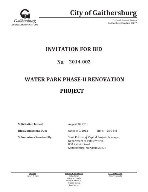
<strong>City</strong> <strong>of</strong> Gaithersburg<br />
31 South Summit Avenue<br />
Gaithersburg, Maryland 20877<br />
INVITATION FOR BID<br />
<strong>No</strong>.<br />
<strong>2014</strong>-<strong>002</strong><br />
WATER PARK PHASE-II RENOVATION<br />
PROJECT<br />
<strong>Solicitation</strong> Issued:<br />
August 30, 2013<br />
<strong>Bid</strong> Submissions Due:<br />
October 9, 2013<br />
Time:<br />
2:00 PM<br />
Submissions Received By:<br />
Sunil Prithviraj, Capital Projects Manager<br />
Department <strong>of</strong> Public Works<br />
800 Rabbitt Road<br />
Gaithersburg, Maryland 20878<br />
MAYOR<br />
Sidney A. Katz<br />
COUNCIL MEMBERS<br />
Jud Ashman<br />
Cathy Drzyzgula<br />
Henry Marraffa, Jr.<br />
Michael Sesma<br />
Ryan Spiegel<br />
CITY MANAGER<br />
Tony Tomasello
TABLE OF CONTENTS<br />
Section I – <strong>No</strong>tice to <strong>Bid</strong>ders ..................................................................................................................... 1<br />
Section II – Introduction and <strong>Solicitation</strong> Schedule ................................................................................ 2<br />
1. Introduction ..................................................................................................................................... 2<br />
2. <strong>Solicitation</strong> Schedule ...................................................................................................................... 2<br />
3. <strong>Solicitation</strong> Questions ..................................................................................................................... 2<br />
a. Submission <strong>of</strong> Questions ................................................................................................... 2<br />
b. Answers to Questions ....................................................................................................... 3<br />
Section III – <strong>Bid</strong> Submission Instructions ................................................................................................ 4<br />
1. <strong>Bid</strong> Submissions ............................................................................................................................. 4<br />
2. <strong>Bid</strong> Contents (“The <strong>Bid</strong>”) ................................................................................................................. 4<br />
Section IV – Scope <strong>of</strong> Work........................................................................................................................ 5<br />
1. Ticket Office Renovations .............................................................................................................. 5<br />
2. Multipurpose Room Renovations ................................................................................................... 5<br />
3. Breezeway ...................................................................................................................................... 6<br />
4. Accessibility Upgrades (ADA) ........................................................................................................ 6<br />
5. Snack Bar ....................................................................................................................................... 7<br />
6. Children’s Pool Toilet...................................................................................................................... 7<br />
7. Gable Archways ............................................................................................................................. 7<br />
Section V – <strong>Bid</strong>der Conditions and Qualifications .................................................................................. 8<br />
1. <strong>Solicitation</strong> <strong>Document</strong>s (<strong>Invitation</strong> <strong>for</strong> <strong>Bid</strong>) ..................................................................................... 8<br />
2. <strong>Bid</strong>der Qualifications....................................................................................................................... 8<br />
3. Contract, Bond and Form In<strong>for</strong>mation ............................................................................................ 8<br />
4. Addendums and Amendments ....................................................................................................... 9<br />
5. The <strong>Bid</strong> ........................................................................................................................................... 9<br />
6. Work Hours and Use <strong>of</strong> Premises .................................................................................................. 9<br />
7. Change Orders, Overhead and Pr<strong>of</strong>it........................................................................................... 10<br />
8. Construction Coordination ............................................................................................................ 10<br />
9. Field Verification and Identification ............................................................................................... 10<br />
10. Materials ....................................................................................................................................... 11<br />
11. Construction Inspections .............................................................................................................. 11<br />
12. Risk <strong>of</strong> Loss .................................................................................................................................. 11<br />
13. Shop and As-Built Drawings ......................................................................................................... 11<br />
14. Warranties .................................................................................................................................... 11<br />
15. Project Closeout ........................................................................................................................... 11<br />
16. Project Schedule .......................................................................................................................... 11<br />
Section VI – General Terms and Conditions .......................................................................................... 12<br />
1. <strong>City</strong>’s Rights .................................................................................................................................. 12
2. Interest in More than One <strong>Bid</strong> and Collusion ............................................................................... 12<br />
3. Accurate In<strong>for</strong>mation .................................................................................................................... 12<br />
4. Addendums and Amendments ..................................................................................................... 12<br />
5. Assignment <strong>of</strong> Contract ................................................................................................................ 12<br />
6. Contract Award ............................................................................................................................. 12<br />
7. Acceptance and Rejection <strong>of</strong> <strong>Bid</strong> Submissions ............................................................................ 13<br />
8. <strong>Bid</strong> Submissions ........................................................................................................................... 13<br />
9. Late <strong>Bid</strong> Submissions ................................................................................................................... 13<br />
10. Modified and Alternate <strong>Bid</strong> Submissions ...................................................................................... 13<br />
11. Errors in <strong>Bid</strong> Submissions ............................................................................................................ 13<br />
12. Errors in <strong>Solicitation</strong> <strong>Document</strong>s .................................................................................................. 13<br />
13. Invoicing ....................................................................................................................................... 14<br />
14. Payment Terms ............................................................................................................................ 14<br />
15. Governing Law ............................................................................................................................. 14<br />
16. Conflict <strong>of</strong> Interest......................................................................................................................... 14<br />
17. Contract Award Protest ................................................................................................................ 14<br />
18. <strong>Solicitation</strong> Protest ........................................................................................................................ 15<br />
19. Additional Goods or Services ....................................................................................................... 15<br />
20. Changes ....................................................................................................................................... 15<br />
21. Cancellation .................................................................................................................................. 15<br />
22. Termination ................................................................................................................................... 15<br />
a. Termination <strong>for</strong> Cause ..................................................................................................... 15<br />
b. Termination <strong>for</strong> Convenience .......................................................................................... 16<br />
c. Termination <strong>for</strong> <strong>No</strong>n-Appropriation <strong>of</strong> Funds ................................................................... 16<br />
23. Confidentiality ............................................................................................................................... 16<br />
24. Dissemination <strong>of</strong> Data .................................................................................................................. 16<br />
25. Inspection <strong>of</strong> Records ................................................................................................................... 16<br />
26. Ownership .................................................................................................................................... 16<br />
27. Retention <strong>of</strong> Records .................................................................................................................... 17<br />
28. Indemnification ............................................................................................................................. 17<br />
29. Inconsistent Provisions ................................................................................................................. 17<br />
30. Insurance ...................................................................................................................................... 17<br />
31. Immigration Re<strong>for</strong>m and Control Act ............................................................................................ 17<br />
32. <strong>No</strong>n-Discrimination Requirements ................................................................................................ 18<br />
33. Independent Contractor Status/Personnel ................................................................................... 18<br />
34. Use <strong>of</strong> Broker ................................................................................................................................ 19<br />
35. Accounting System and Audit ...................................................................................................... 19<br />
36. Patents ......................................................................................................................................... 19<br />
Section VII – Supplemental Terms and Conditions ............................................................................... 20
1. Environmental Concerns and Protection ...................................................................................... 20<br />
2. <strong>City</strong> Representatives .................................................................................................................... 20<br />
3. Contractor’s Assumption <strong>of</strong> Risk .................................................................................................. 20<br />
4. <strong>No</strong> Waiver by the <strong>City</strong> ................................................................................................................... 20<br />
5. Contractor’s Duties and Responsibilities ...................................................................................... 20<br />
a. Duties <strong>of</strong> the Contractor .................................................................................................. 20<br />
b. Supervision and Construction Procedures ...................................................................... 21<br />
c. Review <strong>of</strong> Contract <strong>Document</strong>s ....................................................................................... 21<br />
d. Qualifications <strong>of</strong> the Contractor ....................................................................................... 21<br />
e. Responsibility <strong>for</strong> Those Per<strong>for</strong>ming the Work ................................................................ 21<br />
f. Permits and Licenses ...................................................................................................... 21<br />
g. Compliance with Laws ..................................................................................................... 22<br />
h. Drawings and Specifications at the Site .......................................................................... 22<br />
i. Shop Drawings and Submittals ....................................................................................... 22<br />
j. Use <strong>of</strong> Site ....................................................................................................................... 22<br />
k. Subcontractors ................................................................................................................ 22<br />
l. Payments to Subcontractors ........................................................................................... 23<br />
m. Cutting, Patching and Restoration <strong>of</strong> Work ..................................................................... 23<br />
6. Disputed Work .............................................................................................................................. 23<br />
Section VIII - Attachments ........................................................................................................................ 24
SECTION I – NOTICE TO BIDDERS<br />
This is an invitation <strong>for</strong> bids only, it is not a contract (hereinafter referred to as “<strong>Solicitation</strong>”).<br />
The <strong>City</strong> <strong>of</strong> Gaithersburg, (hereinafter referred to as the “<strong>City</strong>”), shall assume no obligation to pay<br />
or reimburse any person or firm, (hereinafter referred to as the “<strong>Bid</strong>der”), responding to this<br />
<strong>Solicitation</strong> <strong>for</strong> any costs, fees, or expenses incurred in preparation <strong>of</strong> a response to this<br />
<strong>Solicitation</strong>, or <strong>for</strong> any meetings or travel costs related to such response. The <strong>City</strong> is under no<br />
obligation to any responding party until a contract is executed <strong>for</strong> the services described herein.<br />
To enter into a contract with the <strong>City</strong>, companies must be in compliance with the State <strong>of</strong> Maryland Code<br />
<strong>of</strong> Regulations Title 21, State Procurement Regulations.<br />
<strong>Bid</strong>ders must supply, with their <strong>Bid</strong>s, their US Treasury Department Employers’ Identification Number<br />
(Federal ID Number) as such number is shown on their Employer’s Quarterly Federal Tax Return (US<br />
Treasury Department Form <strong>No</strong>. 941). This number shall be inserted on the Response to <strong>Solicitation</strong><br />
Submission Certification in the space provided.<br />
<strong>Bid</strong>ders must be qualified to propose in the State <strong>of</strong> Maryland in accordance with Sections 16-202 and<br />
16-203 <strong>of</strong> the State Finance and Procurement Article <strong>of</strong> the Annotated Code <strong>of</strong> Maryland.<br />
The <strong>City</strong> reserves the right to reject any or all <strong>Bid</strong>s in part or in full and to waive any technicalities<br />
or in<strong>for</strong>malities as best may serve the interests <strong>of</strong> the <strong>City</strong>.<br />
Individuals with a disability who would like to receive this <strong>Solicitation</strong> in another <strong>for</strong>m should<br />
contact the <strong>City</strong>’s Procurement Officer at 301-258-6320.<br />
<strong>Invitation</strong> <strong>for</strong> <strong>Bid</strong> <strong>No</strong>. <strong>2014</strong>-<strong>002</strong><br />
Water Park Phase-II Renovation Project Page 1 <strong>of</strong> 24
SECTION II – INTRODUCTION AND SOLICITATION SCHEDULE<br />
1. Introduction<br />
The <strong>City</strong> is seeking sealed bids <strong>for</strong> commercial construction services <strong>for</strong> the Water Park at Bohrer<br />
Park Phase II Renovations project. Work under the contract awarded pursuant to this <strong>Solicitation</strong>,<br />
(hereinafter referred to as the “Contract”), includes interior and exterior renovations, repairs, and ADA<br />
upgrades to various sections <strong>of</strong> the main building at the Water Park at Bohrer Park, located at 512<br />
South Frederick Avenue, Gaithersburg, Maryland 20877. Such renovations and ADA upgrades<br />
include but are not limited to:<br />
• Renovations to a ticketing <strong>of</strong>fice;<br />
• Renovations to a multipurpose room;<br />
• Renovations to a Breezeway;<br />
• ADA upgrades to men’s and women’s bathrooms/locker rooms;<br />
• Renovations to a snack bar; and<br />
• Renovations to gable archways.<br />
2. <strong>Solicitation</strong> Schedule<br />
The following is the tentative schedule <strong>of</strong> events <strong>for</strong> this <strong>Solicitation</strong>; applicable times are according to<br />
Eastern Standard Time (EST). The <strong>City</strong> reserves the right to modify this schedule; any and all<br />
modifications shall be communicated by addendum or amendment as outlined in Provision four (4),<br />
Addendums and Amendments, in the General Terms and Conditions, <strong>of</strong> this <strong>Solicitation</strong>.<br />
Event<br />
Date<br />
• <strong>Solicitation</strong> Issued: August 30, 2013<br />
• * Pre-<strong>Bid</strong> Meeting: September 18, 2013 at 11:00 a.m.<br />
Location<br />
Water Park at Bohrer Park<br />
512 South Frederick Avenue<br />
Gaithersburg, Maryland 20877<br />
• <strong>Bid</strong>der Questions Due: September 25, 2013 by 3:00 p.m.<br />
• <strong>City</strong>’s Answers to Questions Issued: October 3, 2013<br />
• ** <strong>Bid</strong> Submissions Due: October 9, 2013 by 2:00 p.m.<br />
Submitted To<br />
Sunil Prithviraj, Capital Projects Manager<br />
Department <strong>of</strong> Public Works<br />
800 Rabbitt Road<br />
Gaithersburg, Maryland 20878<br />
* The meeting is not mandatory; however, <strong>Bid</strong>ders are strongly encouraged to attend.<br />
** <strong>Bid</strong>s will be publicly opened and read aloud on the same date and time.<br />
3. <strong>Solicitation</strong> Questions<br />
a. Submission <strong>of</strong> Questions<br />
Questions regarding this <strong>Solicitation</strong> shall be made in writing and must be received by the<br />
date and time due as specified hereinabove; questions shall be submitted using one <strong>of</strong> the<br />
following methods:<br />
<strong>Invitation</strong> <strong>for</strong> <strong>Bid</strong> <strong>No</strong>. <strong>2014</strong>-<strong>002</strong><br />
Water Park Phase-II Renovation Project Page 2 <strong>of</strong> 24
By Mail<br />
Sunil Prithviraj, Capital Projects Manager<br />
Department <strong>of</strong> Public Works<br />
800 Rabbitt Road<br />
Gaithersburg, Maryland 20878<br />
By Email<br />
sprithviraj@gaithersburgmd.gov<br />
b. Answers to Questions<br />
The <strong>City</strong>’s answers to <strong>Bid</strong>der questions will be posted by addendum on the <strong>City</strong>’s website at<br />
www.gaithersburgmd.gov/bids on the date specified herein above.<br />
<strong>Invitation</strong> <strong>for</strong> <strong>Bid</strong> <strong>No</strong>. <strong>2014</strong>-<strong>002</strong><br />
Water Park Phase-II Renovation Project Page 3 <strong>of</strong> 24
SECTION III – BID SUBMISSION INSTRUCTIONS<br />
<strong>Bid</strong>s shall be submitted by the date and time due as provided in the <strong>Solicitation</strong> Schedule and Questions<br />
section <strong>of</strong> this <strong>Solicitation</strong>. <strong>Bid</strong>s submitted via facsimile or e-mail is strictly prohibited; <strong>Bid</strong>s submitted as<br />
such shall be rejected without consideration. The <strong>City</strong> assumes no responsibility <strong>for</strong> delays or errors in<br />
delivery; postmarking by the due date shall not substitute <strong>for</strong> actual receipt.<br />
<strong>Bid</strong>s submitted not in compliance with any <strong>of</strong> the provisions herein shall be rejected as nonresponsive.<br />
1. <strong>Bid</strong> Submissions<br />
<strong>Bid</strong>ders shall submit their bids in a sealed envelope clearly labeled as follows:<br />
• IFB <strong>No</strong>. <strong>2014</strong>-<strong>002</strong><br />
• Water Park Phase II Renovations Project<br />
2. <strong>Bid</strong> Contents (“The <strong>Bid</strong>”)<br />
<strong>Bid</strong>ders shall submit two (2) complete original bids; both sets must bear original signatures and<br />
stamps.<br />
The <strong>Bid</strong> shall contain the following:<br />
a. <strong>City</strong> Forms<br />
The following completed <strong>for</strong>ms and documents which are attached hereto:<br />
• Quotation Sheet<br />
• Amendment Acknowledgement Form<br />
• Affidavit <strong>of</strong> Qualification to <strong>Bid</strong>/Propose Form (Requires <strong>No</strong>tary)<br />
• Conflict <strong>of</strong> Interest Certification Form (Requires <strong>No</strong>tary)<br />
• Litigation and Lien In<strong>for</strong>mation Form<br />
• Response to <strong>Solicitation</strong> Submission Certification Form (Requires <strong>No</strong>tary)<br />
• Project Experience Form<br />
b. Statement <strong>of</strong> Qualifications<br />
The statement <strong>of</strong> qualifications shall include the following:<br />
• <strong>Bid</strong>der’s/Company’s pr<strong>of</strong>ile.<br />
• Resources available <strong>for</strong> this project.<br />
• Provide three (3) example projects demonstrating <strong>Bid</strong>der’s experience in similar type<br />
<strong>of</strong> projects.<br />
• The supporting documents <strong>for</strong> minimum <strong>of</strong> five (5) years commercial construction<br />
experience.<br />
• <strong>Bid</strong>der’s Certificate <strong>of</strong> Qualification (Business registration), to propose in the State <strong>of</strong><br />
Maryland in accordance with Sections 16-202 and 16-203 <strong>of</strong> the State Finance and<br />
Procurement Article <strong>of</strong> the Annotated Code <strong>of</strong> Maryland.<br />
<strong>Invitation</strong> <strong>for</strong> <strong>Bid</strong> <strong>No</strong>. <strong>2014</strong>-<strong>002</strong><br />
Water Park Phase-II Renovation Project Page 4 <strong>of</strong> 24
SECTION IV – SCOPE OF WORK<br />
1. Ticket Office Renovations<br />
The major portion <strong>of</strong> this work comprises interior renovation at the existing ticket <strong>of</strong>fice. The<br />
proposed renovations will involve but not be limited to the following:<br />
a. Demolition<br />
• Remove existing base and wall millwork.<br />
• Remove ceiling tiles and grid.<br />
• Remove wall and floor coverings; strip <strong>of</strong>f drywall to furring members.<br />
• Remove existing windows on north and east walls.<br />
• Remove portions <strong>of</strong> existing Concrete Masonry Unit (CMU) in west wall as indicated<br />
in the drawings to facilitate a larger rough opening <strong>for</strong> the new window. Provide lintel<br />
support to span additional 16 inches as shown in the drawings.<br />
b. Construction<br />
• Install gypsum wallboard furring at all four walls. Provide rigid board insulation to<br />
match furring channel depth.<br />
• Install new carpet and underlayment.<br />
• Install 8’X4’ (approximate) 3 bay teller window with aluminum frame and<br />
polycarbonate resin thermoplastic double pane glazing on the north wall. Install<br />
countersunk deal-tray and speak-through at each end panel as shown in the<br />
drawings.<br />
• Install 5’-6”X4’-8” (approximate) horizontal slider pass-through window with aluminum<br />
frame and polycarbonate resin thermoplastic double pane glazing on east wall.<br />
Install one countersink deal-tray and speak-through as shown in the drawings.<br />
• Install approximately 20 linear feet custom millwork with solid surface countertop<br />
alongside the teller windows on north and east walls. The counter along the east<br />
wall shall be ADA height.<br />
• Install custom plastic laminated casework on south wall. The wall casework will be<br />
open “cubbies” type shelving. The bottom casework will be shallow depth base<br />
cabinets as shown in the drawings.<br />
• Install new ceiling grid and acoustical tiles.<br />
• Relocate existing PA amplifiers and associated controls per the drawings; provide a<br />
new shelf to support.<br />
• Extend existing telephone system to serve three handsets in the ticket <strong>of</strong>fice. Voice<br />
circuits shall terminate at exiting BIX blocks.<br />
• Extend existing data system to serve three workstations in the ticket <strong>of</strong>fice. Data<br />
circuits shall terminate at the existing patch panel located in the Data Room.<br />
• Provide power outlets under and above new countertops to support various<br />
electronic equipments.<br />
• Provide new 2'X4' direct/indirect fluorescent luminaries.<br />
2. Multipurpose Room Renovations<br />
a. Demolition<br />
<strong>Invitation</strong> <strong>for</strong> <strong>Bid</strong> <strong>No</strong>. <strong>2014</strong>-<strong>002</strong><br />
Water Park Phase-II Renovation Project Page 5 <strong>of</strong> 24
3. Breezeway<br />
• Remove existing base and wall cabinets at the north wall. Remove existing hand<br />
wash sink and cap plumbing outlets, remove existing receptacles below countertop.<br />
• Remove existing millwork base and wall cabinets at the east wall <strong>of</strong> first aid area.<br />
b. Construction<br />
• Install new custom millwork with solid surface counter. Replace existing power<br />
receptacles above the countertop with new stainless steel receptacles. Remove<br />
existing receptacles below countertop.<br />
• Install new custom millwork with solid surface counter. Replace existing power<br />
receptacles above and below countertop with new stainless steel receptacles.<br />
• Replace existing luminaries to provide greater illumination at the breezeway located outside<br />
the east wall <strong>of</strong> the ticket <strong>of</strong>fice.<br />
• Install Post-rope Queue Control System outside the north wall <strong>of</strong> ticket <strong>of</strong>fice. The posts shall<br />
be in fixed position with removable rope section.<br />
• Add concrete pavement at existing planter as indicated in plans. Protect and preserve the<br />
remaining planter during construction.<br />
• Relocate existing bicycle stand.<br />
4. Accessibility Upgrades (ADA)<br />
Major portions <strong>of</strong> the upgrades will be in the existing male and female changing rooms and shower<br />
areas. Other upgrades will be at the snack bar and the existing toilet at the children’s pool area.<br />
a. Men’s Shower Area<br />
• Modify and adjust mounting height <strong>for</strong> entire lavatory counter and backsplash in changing<br />
room to comply with ADA. Replace one existing faucet with wrist blade ADA compliant<br />
faucet.<br />
• Modify one toilet compartment into ambulatory stall in changing room. This may involve<br />
slight adjustment to existing partition, replacement <strong>of</strong> existing door and adding new grab<br />
bars.<br />
• Modify a shower and controls to comply with ADA in the existing gang shower. Install<br />
privacy curtain to the modified shower area. Add fold down shower seat.<br />
• Modify and shorten existing bench at the location <strong>of</strong> accessible locker alcove to enable<br />
ease <strong>of</strong> access as shown in the drawings.<br />
• Provide signage outside the rear (east side) doors to indicate the location and route <strong>of</strong><br />
accessible door.<br />
b. Women’s Shower Area<br />
• Modify and adjust mounting height <strong>for</strong> entire lavatory counter and backsplash in changing<br />
rooms to comply with ADA. Replace one existing faucet with wrist blade ADA compliant<br />
faucet.<br />
• Modify one toilet compartment into ambulatory stall in changing room. This may involve<br />
slight adjustment to existing partition, replacement <strong>of</strong> existing door and adding new grab<br />
bars.<br />
<strong>Invitation</strong> <strong>for</strong> <strong>Bid</strong> <strong>No</strong>. <strong>2014</strong>-<strong>002</strong><br />
Water Park Phase-II Renovation Project Page 6 <strong>of</strong> 24
• Add accessible dressing area to the female changing room. This would require<br />
demolition and addition <strong>of</strong> CMU partition wall in existing changing areas, addition <strong>of</strong> grab<br />
bars, and installation <strong>of</strong> a new cubicle curtain.<br />
• Modify the existing single occupant shower to comply with ADA by removing existing<br />
shower pan and adding new terrazzo shower area. Installing new grab bars, fold down<br />
shower seat and adjustable accessible shower head and wand.<br />
• Modify and shorten existing bench at the location <strong>of</strong> accessible locker alcove to enable<br />
ease <strong>of</strong> access as shown in the drawings.<br />
• Provide signage outside the rear (east side) doors to indicate the location and route <strong>of</strong><br />
accessible door.<br />
5. Snack Bar<br />
Lower the sill, indoor counter and associated screen window, as well as the roll-up overhead shutter<br />
at the side serving window <strong>of</strong> the snack bar.<br />
6. Children’s Pool Toilet<br />
Replace metal door with in kind outward swing door as shown in the drawings.<br />
7. Gable Archways<br />
a. Front and Food Court<br />
• Completely remove Direct Applied Exterior Finishing System (DEFS).<br />
• Repair or replace rotted plywood sheathing and framing where necessary.<br />
• Metal ro<strong>of</strong> must be installed per manufacturer’s installation instructions.<br />
• All repairs shall be done as per the drawings.<br />
b. Clock Tower<br />
• Completely remove DEFS system.<br />
• Repair or replace rotted plywood sheathing and framing where needed.<br />
• Metal ro<strong>of</strong> must be installed per manufacturer’s instructions.<br />
• Install <strong>City</strong> provided clock.<br />
• All repairs shall be done as per the drawings.<br />
c. Golf Park Entryway<br />
• Completely remove DEFS System.<br />
• Repair or replace rotted plywood sheathing and framing where needed.<br />
• Install new approved EIFS Class PB System on the walls.<br />
• Metal ro<strong>of</strong> must be installed per manufacturer’s instructions.<br />
• Re-install signage lettering.<br />
• All repairs shall be done as per the drawings.<br />
<strong>Bid</strong>ders shall refer to Attachment C, Drawings and Specifications, <strong>for</strong> the complete Work Scope,<br />
materials and repair procedures.<br />
<strong>Invitation</strong> <strong>for</strong> <strong>Bid</strong> <strong>No</strong>. <strong>2014</strong>-<strong>002</strong><br />
Water Park Phase-II Renovation Project Page 7 <strong>of</strong> 24
SECTION V – BIDDER CONDITIONS AND QUALIFICATIONS<br />
1. <strong>Solicitation</strong> <strong>Document</strong>s (<strong>Invitation</strong> <strong>for</strong> <strong>Bid</strong>)<br />
a. <strong>Bid</strong>ders are expected to examine all documents, specifications and <strong>for</strong>ms (“<strong>Solicitation</strong><br />
<strong>Document</strong>s”) carefully. If doubt exists as to the meaning or intent <strong>of</strong> anything in any <strong>of</strong> the<br />
<strong>Solicitation</strong> <strong>Document</strong>s, <strong>Bid</strong>ders shall make an inquiry as to such meaning or intent prior to<br />
submitting their bid. The submission <strong>of</strong> a bid shall indicate that the <strong>Bid</strong>der thoroughly<br />
understands all said <strong>Bid</strong> <strong>Document</strong>s.<br />
b. Each bid shall include a price <strong>for</strong> each item <strong>of</strong> the work proposed. Where the attached<br />
Schedule <strong>of</strong> Prices <strong>Bid</strong> Sheet requests a lump sum price, a lump sum price shall be stated.<br />
Where the Schedule <strong>of</strong> Prices <strong>Bid</strong> Sheet requests a unit price, a unit price shall be stated. In<br />
either event, the <strong>City</strong> shall not be responsible <strong>for</strong> any error in the approximate quantities<br />
stated in the Schedule <strong>of</strong> Prices <strong>Bid</strong> Sheet.<br />
2. <strong>Bid</strong>der Qualifications<br />
a. The <strong>City</strong> may make such investigation, as it deems necessary, to determine the qualifications<br />
and ability <strong>of</strong> the <strong>Bid</strong>der, to furnish the supplies, materials, equipment, labor, and services<br />
necessary to complete the work within the <strong>City</strong>’s schedule. The <strong>Bid</strong>der shall furnish to the<br />
<strong>City</strong> all in<strong>for</strong>mation and data <strong>for</strong> this purpose as the <strong>City</strong> may request including the attached<br />
Project Experience Form. The <strong>City</strong> reserves the right to reject any bid if the evidence<br />
submitted or investigation fails to satisfy the <strong>City</strong>, that a <strong>Bid</strong>der is properly qualified to carry<br />
out the obligations contemplated in the Contract. Following verification <strong>of</strong> the <strong>Bid</strong>der’s<br />
qualifications and bid, a Contract shall be awarded to the lowest responsive and responsible<br />
<strong>Bid</strong>der.<br />
b. The <strong>City</strong> reserves the right to reject any bid if evidenced that a <strong>Bid</strong>der is not qualified to<br />
per<strong>for</strong>m under the Contract awarded pursuant to this <strong>Solicitation</strong>.<br />
c. Work must be per<strong>for</strong>med by a firm with a minimum <strong>of</strong> five (5) years commercial construction<br />
experience.<br />
d. An experienced full time supervisor, who has a minimum <strong>of</strong> three (3) years’ experience in<br />
commercial construction, shall be assigned to this project. The supervisor shall be present at<br />
all times during the construction.<br />
3. Contract, Bond and Form In<strong>for</strong>mation<br />
a. The Contract consists <strong>of</strong> Contract pages, <strong>Solicitation</strong> document (<strong>Bid</strong>der Conditions, General<br />
Conditions, Plans, Specifications) as Exhibit-A and the <strong>Bid</strong> (as defined in <strong>Bid</strong>der instructions<br />
section) as Exhibit-B. The <strong>City</strong> expects to award a fixed price contract based on the proposed<br />
bid <strong>for</strong> a specific period on present assumptions.<br />
b. If the Principal is a partnership, the full names <strong>of</strong> all general partners must be inserted in the<br />
Contract; which must recite they are the general partners <strong>of</strong> the partnership. All general<br />
partners must execute the Contract and affidavit as individuals.<br />
c. The State <strong>of</strong> Incorporation <strong>of</strong> each corporation must be inserted in the Contract and the<br />
documents must be executed under the corporate seal <strong>of</strong> said corporations and attested by<br />
the secretary or other appropriate <strong>of</strong>fice. A corporate signature must con<strong>for</strong>m exactly to<br />
correct chartered name on the corporate seal. If executed by an <strong>of</strong>ficer other than the<br />
president, evidence <strong>of</strong> authority granted such other <strong>of</strong>ficer, must be furnished.<br />
<strong>Invitation</strong> <strong>for</strong> <strong>Bid</strong> <strong>No</strong>. <strong>2014</strong>-<strong>002</strong><br />
Water Park Phase-II Renovation Project Page 8 <strong>of</strong> 24
d. <strong>Bid</strong> bond is not required <strong>for</strong> this project, however if the <strong>Bid</strong>der withdraws a bid, it may become<br />
basis to reject future bids submitted to the <strong>City</strong>. The selected Contractor shall provide a 100%<br />
Per<strong>for</strong>mance and Payment Bond prior to the Contract execution. The date <strong>of</strong> the Payment<br />
Bond must be consistent with that <strong>of</strong> the Contract or subsequent thereto. A certified copy <strong>of</strong><br />
the Power <strong>of</strong> Attorney <strong>of</strong> the attorney-in-fact executing the Payment Bond, bearing the same<br />
date as the Payment Bond and certified by a manual signature, must be attached to each<br />
copy <strong>of</strong> the Payment Bond. Facsimile signature on the certification will not be accepted.<br />
e. The Contractor shall administer this project in con<strong>for</strong>mance with all laws, regulations and<br />
policies <strong>of</strong> the State <strong>of</strong> Maryland, Montgomery County, and the <strong>City</strong> <strong>of</strong> Gaithersburg.<br />
4. Addendums and Amendments<br />
Any Addenda/Amendments issued after the <strong>Invitation</strong> <strong>for</strong> <strong>Bid</strong> and be<strong>for</strong>e the opening <strong>of</strong> bids shall be<br />
included in the bid. All Addenda/Amendments will be posted on the <strong>City</strong>’s website.<br />
5. The <strong>Bid</strong><br />
The bid as defined in the “<strong>Bid</strong>der Instructions” section shall be returned in its entirety; all <strong>of</strong> which will<br />
become part <strong>of</strong> the Contract.<br />
6. Work Hours and Use <strong>of</strong> Premises<br />
a. <strong>No</strong>rmal Facility Operation Hours<br />
(1) The facility will be closed to public from mid September to late March. Water Park is<br />
available <strong>for</strong> construction Monday-Saturday 7:00 a.m. - 6:00 p.m. Additional access<br />
shall be coordinated with the <strong>City</strong> assigned Project Manager.<br />
(2) Work shall not be per<strong>for</strong>med other than normal working hours except when such<br />
timeliness <strong>of</strong> per<strong>for</strong>mance is necessary to safeguard life or property. Deviation from<br />
normal working hours shall be authorized by the Project Manager.<br />
(3) Requests <strong>for</strong> deviation from normal working hours shall be submitted in writing to<br />
the <strong>City</strong>’s Project Manager not less than seventy-two (72) hours in advance <strong>of</strong> the<br />
proposed work period.<br />
b. Traffic, Safety and Interruptions<br />
The Contractor shall provide signs to prevent traffic from interfering with work. The<br />
Contractor shall take all necessary safety precautions to protect occupants and the facility.<br />
c. Contractor Use <strong>of</strong> Premises<br />
The Contractor shall limit his use <strong>of</strong> the premises to the work indicated, so as to allow <strong>for</strong> <strong>City</strong><br />
occupancy and use.<br />
(1) Confine operations at the site to the areas permitted under the Contract. Portions <strong>of</strong><br />
the site beyond areas on which work is indicated are not to be disturbed. Con<strong>for</strong>m<br />
to site rules and regulations affecting the work while engaged in project<br />
construction.<br />
(2) Keep existing egresses outside the construction zone clear and available to the<br />
public during normal facility operation hours. Do not use these areas <strong>for</strong> parking or<br />
storage <strong>of</strong> materials. Parking areas and areas <strong>for</strong> storage <strong>of</strong> materials shall be<br />
limited to those areas within the construction zone.<br />
(3) Do not unreasonably encumber the site with materials or equipment. Confine<br />
storage <strong>of</strong> materials and locations <strong>of</strong> storage sheds to the areas within the<br />
construction zone. If additional storage is necessary, obtain and pay <strong>for</strong> such<br />
storage <strong>of</strong>f site.<br />
<strong>Invitation</strong> <strong>for</strong> <strong>Bid</strong> <strong>No</strong>. <strong>2014</strong>-<strong>002</strong><br />
Water Park Phase-II Renovation Project Page 9 <strong>of</strong> 24
7. Change Orders, Overhead and Pr<strong>of</strong>it<br />
The Change Orders must be approved in advance, in writing and that in submitting Change Order<br />
requests, they must indicate the fixed price, which cannot exceed the indicated percentages <strong>for</strong> the<br />
enumerated categories.<br />
Overhead Pr<strong>of</strong>it Commission<br />
To the Contractor <strong>for</strong> work per<strong>for</strong>med by its own<br />
<strong>for</strong>ces.<br />
To Contractor <strong>for</strong> work per<strong>for</strong>med by other than its<br />
own <strong>for</strong>ces.<br />
To Subcontractor <strong>for</strong> work per<strong>for</strong>med by its own<br />
<strong>for</strong>ces.<br />
To the Subcontractor <strong>for</strong> work per<strong>for</strong>med by other<br />
than its own <strong>for</strong>ces.<br />
10% Plus 5% --<br />
-- -- 10%<br />
10% -- --<br />
-- Plus 10% --<br />
8. Construction Coordination<br />
a. The Contractor shall submit a Project Schedule to the <strong>City</strong>’s Project Manager and get written<br />
approval, prior to starting the work.<br />
b. An experienced full time supervisor who has verifiable, responsible and a minimum <strong>of</strong> three<br />
(3) years construction experience shall be assigned to this project. The supervisor shall be<br />
present at all times during the project execution.<br />
c. The Contractor shall prepare and submit a Daily Report to the <strong>City</strong>’s Project Manager. The<br />
Daily Report shall include the following:<br />
• Name <strong>of</strong> project;<br />
• Project number;<br />
• Date <strong>of</strong> report;<br />
• Weather conditions;<br />
• Manpower status on each type <strong>of</strong> work being per<strong>for</strong>med, by building;<br />
• Overtime worked and planned;<br />
• Work progress;<br />
• Environmental problems and corrections;<br />
• Other in<strong>for</strong>mation, such as special events or occurrences, accidents,<br />
recommendations, suggestions, visitors, major equipment or materials received,<br />
tests, inspections, equipment start-up and check-out, and occupancy; and<br />
• The Contractor shall take the necessary action required to specifically alert the <strong>City</strong>’s<br />
Project Manager to items which could result in claims.<br />
9. Field Verification and Identification<br />
The Contractor shall verify all existing in<strong>for</strong>mation, conditions and dimensions by field measurement<br />
within one week <strong>of</strong> the beginning <strong>of</strong> construction activity. This shall be done prior to any demolition,<br />
fabrication <strong>of</strong> materials or construction. The Contractor shall report any discrepancies or conflicts to<br />
the structural engineer. In the event that field conditions differ significantly from the Contract<br />
documents, a revision will be issued by the structural engineer with sketches and/or revised Contract<br />
documents.<br />
<strong>Invitation</strong> <strong>for</strong> <strong>Bid</strong> <strong>No</strong>. <strong>2014</strong>-<strong>002</strong><br />
Water Park Phase-II Renovation Project Page 10 <strong>of</strong> 24
10. Materials<br />
The Contractor shall refer to plans and specification <strong>for</strong> materials, any deviations shall be preapproved<br />
by the <strong>City</strong>’s Project Manager.<br />
11. Construction Inspections<br />
Contractor shall coordinate all required inspections. The Contractor shall allow inspections at any<br />
time and honor the inspector’s requests to observe the work. The inspector shall not unduly hinder<br />
the Contractor’s progress with unreasonable requests or delays.<br />
12. Risk <strong>of</strong> Loss<br />
During per<strong>for</strong>mance <strong>of</strong> the work and until final acceptance there<strong>of</strong>, the Contractor shall be under an<br />
absolute obligation to protect the finished and unfinished work against any damage, loss, or injury.<br />
The Contractor shall take proper precautions to protect the finished work from loss or damage,<br />
pending completion and final acceptance <strong>of</strong> all work included in the Contract. Such precautions shall<br />
not relieve the Contractor from any and all liability and responsibility <strong>for</strong> loss or damage to the work<br />
occurring be<strong>for</strong>e final acceptance by the <strong>City</strong>. Such loss or damage shall be at the risk <strong>of</strong> and borne<br />
by the Contractor, whether arising from acts or omissions <strong>of</strong> the Contractor or others and whether or<br />
not covered by the Contractor's Builder's Risk Insurance. In the event <strong>of</strong> any such loss or damage,<br />
the Contractor shall <strong>for</strong>thwith repair, replace and make good the work without extension <strong>of</strong> time.<br />
There<strong>for</strong>e, the Contractor shall take special precautions throughout all its operations to guard against<br />
fire and shall reduce the amount <strong>of</strong> flammable materials stored at the site to the minimum amount<br />
consistent with the proper handling and storing <strong>of</strong> such materials.<br />
13. Shop and As-Built Drawings<br />
The Contractor shall provide Shop Drawings as needed and As-Built Drawings shall be provided as<br />
part <strong>of</strong> the project closing documents.<br />
14. Warranties<br />
The Contractor shall provide a written warranty <strong>for</strong> a minimum <strong>of</strong> one (1) year to cover defects in<br />
materials and workmanship. Should the materials manufacturer’s warranty exceed one (1) year, the<br />
later should apply. All warranties shall start from the date <strong>of</strong> project acceptance.<br />
15. Project Closeout<br />
Upon written notification by the Contractor that the work is finally complete, the <strong>City</strong> will conduct a<br />
final inspection <strong>of</strong> the work. When the <strong>City</strong> determines that the work has been satisfactorily<br />
completed and the Contract requirements are fully satisfied, including warranty documents, final<br />
inspections and maintenance manuals, the <strong>City</strong> will issue a Project Acceptance Letter and process<br />
the final payment.<br />
16. Project Schedule<br />
The Contractor shall schedule the work within fifteen (15) days from the date <strong>of</strong> <strong>No</strong>tice to Proceed.<br />
The Contractor shall complete the work within twelve (12) weeks from the date <strong>of</strong> project kick-<strong>of</strong>f.<br />
<strong>Invitation</strong> <strong>for</strong> <strong>Bid</strong> <strong>No</strong>. <strong>2014</strong>-<strong>002</strong><br />
Water Park Phase-II Renovation Project Page 11 <strong>of</strong> 24
SECTION VI – GENERAL TERMS AND CONDITIONS<br />
The Terms and Conditions <strong>of</strong> this <strong>Solicitation</strong> document or <strong>of</strong> the Contract awarded pursuant to this<br />
<strong>Solicitation</strong> apply in the event <strong>of</strong> conflict with the <strong>Bid</strong>der’s bid submission, and are not subject to change<br />
by reasons <strong>of</strong> written or verbal statement by the <strong>Bid</strong>der unless accepted in writing by the <strong>City</strong>.<br />
1. <strong>City</strong>’s Rights<br />
The <strong>City</strong> shall assume no obligation to pay or reimburse any person or firm responding to this<br />
<strong>Solicitation</strong> <strong>for</strong> any costs, fees, or expenses incurred in preparation <strong>of</strong> a response to this <strong>Solicitation</strong>,<br />
or <strong>for</strong> any meetings or travel costs related to such response. The <strong>City</strong> is under no obligation to any<br />
responding party until a Contract is executed <strong>for</strong> the services described herein.<br />
2. Interest in More than One <strong>Bid</strong> and Collusion<br />
Multiple <strong>Bid</strong>s submitted in response to a single <strong>Solicitation</strong> from an individual, firm, partnership,<br />
corporation, affiliate or association under the same or different names shall be rejected. Reasonable<br />
grounds <strong>for</strong> believing that any <strong>Bid</strong>der has interest in more than one <strong>Bid</strong> <strong>for</strong> a single <strong>Solicitation</strong>, both<br />
as a <strong>Bid</strong>der and as a subcontractor <strong>for</strong> another <strong>Bid</strong>der, shall result in rejection <strong>of</strong> all <strong>Bid</strong> submissions<br />
in which the <strong>Bid</strong>der has interest. However, an individual, firm, partnership, corporation, affiliate, or<br />
association acting only as a subcontractor may be included as a subcontractor <strong>for</strong> two or more<br />
<strong>Bid</strong>ders submitting a <strong>Bid</strong> in response to a single <strong>Solicitation</strong>.<br />
Any or all <strong>Bid</strong> submissions may be rejected if reasonable grounds exist <strong>for</strong> believing that collusion<br />
exists among <strong>Bid</strong>ders. <strong>Bid</strong>ders rejected under any <strong>of</strong> these provisions shall be disqualified from<br />
responding to a Re-solicitation <strong>for</strong> the same work.<br />
3. Accurate In<strong>for</strong>mation<br />
The <strong>Bid</strong>der certifies that all in<strong>for</strong>mation provided, or will be provided to the <strong>City</strong> is true and correct and<br />
may be relied upon by the <strong>City</strong> in awarding, modifying, making payments, or taking any other action<br />
with respect to the Contract awarded pursuant to this <strong>Solicitation</strong>. Any false or misleading in<strong>for</strong>mation<br />
is grounds <strong>for</strong> the <strong>City</strong> to terminate the Contract award to the <strong>Bid</strong>der. Such termination shall relieve<br />
the <strong>City</strong> <strong>of</strong> any direct or consequential damages or costs incurred by the Contractor.<br />
4. Addendums and Amendments<br />
In the event addendums or amendments are issued to this <strong>Solicitation</strong>, all Terms and Conditions <strong>of</strong><br />
this <strong>Solicitation</strong> document govern and apply unless specifically modified in such addendums or<br />
amendments. Verbal or written answers to questions not posted on the <strong>City</strong>’s website, relative to this<br />
<strong>Solicitation</strong> shall not be considered valid or en<strong>for</strong>ceable.<br />
It is the responsibility <strong>of</strong> the <strong>Bid</strong>der to inquire about and obtain any addendums or amendments<br />
issued to this <strong>Solicitation</strong>. Any and all addendums or amendments shall be posted on the <strong>City</strong>’s<br />
website at www.gaithersburgmd.gov/bids.<br />
5. Assignment <strong>of</strong> Contract<br />
It is mutually understood and agreed that, once awarded the Contract pursuant to this <strong>Solicitation</strong>, the<br />
Contractor shall not assign, transfer, convey, sublet or otherwise dispose <strong>of</strong> its Contract or its right,<br />
title or interest therein, or its power to execute such Contract, to any other person, vendor, or<br />
corporation, without the prior written consent <strong>of</strong> the <strong>City</strong> Manager or designee, but in no case shall<br />
such consent relieve the Contractor from its obligations under the Contract, or change the terms <strong>of</strong><br />
the Contract.<br />
6. Contract Award<br />
It is the intent <strong>of</strong> the <strong>City</strong> to award the Contract pursuant to this <strong>Solicitation</strong> to one <strong>Bid</strong>der; however,<br />
the <strong>City</strong> reserves the right to award the Contract to multiple <strong>Bid</strong>ders in whole or in part. Award shall<br />
be to the <strong>Bid</strong>der whose <strong>Bid</strong> the <strong>City</strong> considers, in its sole discretion, to be in the best interest <strong>of</strong> the<br />
<strong>City</strong>, taking into consideration all aspects <strong>of</strong> the technical and Cost <strong>Bid</strong>s. If <strong>for</strong> any reason, through no<br />
fault <strong>of</strong> the <strong>City</strong>, the Contract is not signed and executed within thirty (30) days <strong>of</strong> the <strong>No</strong>tice <strong>of</strong> Intent<br />
<strong>Invitation</strong> <strong>for</strong> <strong>Bid</strong> <strong>No</strong>. <strong>2014</strong>-<strong>002</strong><br />
Water Park Phase-II Renovation Project Page 12 <strong>of</strong> 24
to Award, the <strong>City</strong> may recommend award to the next most responsive and responsible <strong>Bid</strong>der, or call<br />
<strong>for</strong> new <strong>Bid</strong>s entirely.<br />
All Contracts shall be signed by the <strong>City</strong> Manager or Designee; any Contract not signed as such shall<br />
not be considered valid or en<strong>for</strong>ceable.<br />
7. Acceptance and Rejection <strong>of</strong> <strong>Bid</strong> Submissions<br />
The <strong>City</strong> reserves the right to accept or reject any or all <strong>Bid</strong>s in whole or in part, to waive any<br />
technicalities or in<strong>for</strong>malities in <strong>Bid</strong>s, and to postpone or cancel the <strong>Bid</strong> process at any time if<br />
determined to serve the best interest <strong>of</strong> the <strong>City</strong>. The <strong>City</strong> may reject a <strong>Bid</strong> from any <strong>Bid</strong>der in arrears<br />
or in default to the <strong>City</strong> on any Contract, debt, or other obligation.<br />
<strong>Bid</strong>s shall remain binding <strong>for</strong> one-hundred eighty (180) calendar days following the date <strong>of</strong> opening;<br />
<strong>Bid</strong>s may not be withdrawn any time within this period. In the event an award is not made during<br />
such period, all <strong>Bid</strong>s shall be automatically extended <strong>for</strong> an additional one-hundred eighty (180)<br />
calendar days. <strong>Bid</strong>s shall automatically be renewed until such time as either an award is made or<br />
proper notice is given to the <strong>City</strong> <strong>of</strong> the <strong>Bid</strong>der’s intent to withdraw its <strong>Bid</strong>. <strong>Bid</strong>s may only be<br />
withdrawn by submitting notice in writing at least fifteen (15) calendar days prior to the expiration <strong>of</strong><br />
the then current one-hundred eighty (180) calendar days period.<br />
8. <strong>Bid</strong> Submissions<br />
All <strong>Bid</strong> submissions shall be submitted in a sealed envelope by the date and time due and to the<br />
location specified in this <strong>Solicitation</strong>. The <strong>Solicitation</strong> number and title must be clearly visible on the<br />
outside <strong>of</strong> the sealed envelope. <strong>Bid</strong> submissions via facsimile or e-mail is strictly prohibited.<br />
Any <strong>Bid</strong> submitted not in compliance with this provision shall be rejected as being nonresponsive.<br />
9. Late <strong>Bid</strong> Submissions<br />
It is the responsibility <strong>of</strong> the <strong>Bid</strong>der to ensure delivery <strong>of</strong> their <strong>Bid</strong> submission by the date and time<br />
due and to the designated location specified in this <strong>Solicitation</strong>. <strong>Bid</strong>s delivered late or to any <strong>of</strong>fice or<br />
location other than the designated location shall not be considered and will be returned unopened to<br />
the <strong>Bid</strong>der.<br />
The <strong>City</strong> assumes no responsibility <strong>for</strong> delays or errors in delivery. Postmarking by the due date shall<br />
not substitute <strong>for</strong> actual receipt.<br />
10. Modified and Alternate <strong>Bid</strong> Submissions<br />
<strong>Bid</strong>ders are expected to clearly respond to the requirements <strong>of</strong> this <strong>Solicitation</strong>. Modified or alternate<br />
<strong>Bid</strong> submissions <strong>for</strong> the services or materials required will result in rejection <strong>of</strong> the <strong>Bid</strong> as being<br />
nonresponsive.<br />
11. Errors in <strong>Bid</strong> Submissions<br />
<strong>Bid</strong>ders shall thoroughly examine and are expected to be familiar with the Specifications in this<br />
<strong>Solicitation</strong>. The failure or omission <strong>of</strong> any <strong>Bid</strong>der to receive, examine, or understand this <strong>Solicitation</strong>,<br />
shall in no way relieve any <strong>Bid</strong>der <strong>of</strong> its obligations with respect to this <strong>Solicitation</strong> or the subsequent<br />
Contract awarded pursuant to this <strong>Solicitation</strong>. The submission <strong>of</strong> a <strong>Bid</strong> shall be taken as prima facie<br />
evidence <strong>of</strong> compliance with this paragraph. Obvious error(s) in calculations in a <strong>Bid</strong> may not be<br />
corrected without the prior consent <strong>of</strong> the <strong>City</strong> and in the <strong>City</strong>’s sole discretion, and may be cause to<br />
reject the <strong>Bid</strong>, whether or not the <strong>City</strong> has accepted the <strong>Bid</strong>.<br />
12. Errors in <strong>Solicitation</strong> <strong>Document</strong>s<br />
<strong>Bid</strong>ders shall carefully and thoroughly examine all <strong>Solicitation</strong> documents <strong>for</strong> accuracy and<br />
completeness. <strong>No</strong> claim by any <strong>Bid</strong>der shall be allowed on the basis that any <strong>of</strong> the <strong>Solicitation</strong><br />
documents are inaccurate or incomplete.<br />
<strong>Invitation</strong> <strong>for</strong> <strong>Bid</strong> <strong>No</strong>. <strong>2014</strong>-<strong>002</strong><br />
Water Park Phase-II Renovation Project Page 13 <strong>of</strong> 24
13. Invoicing<br />
Original invoices shall include, at a minimum, the <strong>Bid</strong>der’s business name, address, telephone and<br />
fax numbers, and if applicable, email address and corresponding Purchase Order Number. Invoices<br />
shall be submitted to:<br />
<strong>City</strong> <strong>of</strong> Gaithersburg<br />
Accounts Payable<br />
31 South Summit Avenue.<br />
Gaithersburg, Maryland 20877<br />
14. Payment Terms<br />
The <strong>City</strong>’s standard terms <strong>of</strong> payment are net thirty (30) days. The <strong>City</strong> may reject as nonresponsive<br />
any <strong>Bid</strong> which is conditioned on payment <strong>of</strong> proper invoices in less than thirty (30) days; however, this<br />
does not preclude a <strong>Bid</strong>der from providing a prompt payment discount <strong>for</strong> payment <strong>of</strong> invoices in less<br />
than thirty (30) days. Payments considered past due may be subject to incurred interest not to<br />
exceed one percent (1%) per month.<br />
15. Governing Law<br />
The Contract awarded pursuant to this <strong>Solicitation</strong> shall be construed in accordance with the laws and<br />
regulations <strong>of</strong> the Federal Government, State <strong>of</strong> Maryland, and the <strong>City</strong> <strong>of</strong> Gaithersburg. For<br />
purposes <strong>of</strong> litigation involving the Contract, exclusive venue and jurisdiction shall be in the Circuit<br />
Court <strong>of</strong> Maryland <strong>for</strong> Montgomery County, District Court <strong>of</strong> Maryland <strong>for</strong> Montgomery County or the<br />
United States District Court <strong>of</strong> Maryland.<br />
16. Conflict <strong>of</strong> Interest<br />
In accordance with the <strong>City</strong>’s financial disclosure and conflict <strong>of</strong> interest provisions in the <strong>City</strong>’s ethics<br />
law, a prerequisite <strong>for</strong> payment pursuant to the terms <strong>of</strong> the Contract awarded pursuant to this<br />
<strong>Solicitation</strong> is that the Contractor shall complete and submit a Conflict <strong>of</strong> Interest Certification Form.<br />
17. Contract Award Protest<br />
All disputes arising under the Contract awarded pursuant to this <strong>Solicitation</strong>, not disposed <strong>of</strong> by<br />
agreement, must be decided under procedures a-d below. Pending final resolution <strong>of</strong> a dispute, the<br />
Contractor shall proceed diligently with Contract per<strong>for</strong>mance. Any claim <strong>for</strong> dispute must be in<br />
writing <strong>for</strong> a sum certain and must be fully supported by all cost and pricing in<strong>for</strong>mation.<br />
a. All disputes, claims, questions <strong>of</strong> fact or interpretations <strong>of</strong> the Contract documents not<br />
disposed <strong>of</strong> by agreement or express provision <strong>of</strong> the Contract arising between the <strong>City</strong> and<br />
the Contractor after per<strong>for</strong>mance <strong>of</strong> the Contract has commenced but be<strong>for</strong>e final payment<br />
and termination <strong>of</strong> the Contract, are decided by the <strong>City</strong> Manager or designee.<br />
b. The <strong>City</strong> Manager or designee shall give the Contractor not less than three (3) working days<br />
to submit documentation and written reasons supporting the Contractor's position in the<br />
dispute. The <strong>City</strong> Manager or designee may consider any other in<strong>for</strong>mation or written<br />
submissions from <strong>City</strong> employees or agents and may conduct an in<strong>for</strong>mal, non-record<br />
hearing <strong>for</strong> receipt <strong>of</strong> testimony, evidence, and argument. The <strong>City</strong> Attorney may participate<br />
in the hearings to protect the <strong>City</strong>'s interest.<br />
c. The <strong>City</strong> Manager or designee shall render a decision in writing, stating reasons <strong>for</strong> such<br />
decision and provide copies to the Contractor and the <strong>City</strong> Attorney. If the decision is mailed<br />
to the Contractor, it must be mailed "Certified" and dated the date <strong>of</strong> mailing; otherwise, it<br />
must be dated the date <strong>of</strong> delivery to the Contractor.<br />
d. The written decision <strong>of</strong> the <strong>City</strong> Manager or designee shall be sent to all parties. Such<br />
decision may be submitted to Binding Arbitration by either party under the auspices <strong>of</strong> an<br />
arbitrator appointed by the American Arbitration Association.<br />
<strong>Invitation</strong> <strong>for</strong> <strong>Bid</strong> <strong>No</strong>. <strong>2014</strong>-<strong>002</strong><br />
Water Park Phase-II Renovation Project Page 14 <strong>of</strong> 24
18. <strong>Solicitation</strong> Protest<br />
Any protest <strong>of</strong> this <strong>Solicitation</strong> shall be in writing to the <strong>City</strong> Attorney. The provisions <strong>of</strong> COMAR Title<br />
21.01.03.01A (7), State Procurement Regulations, do not apply to municipalities and are not<br />
applicable to this <strong>Solicitation</strong>.<br />
Protests <strong>of</strong> alleged improprieties in this <strong>Solicitation</strong> which are apparent be<strong>for</strong>e the <strong>Solicitation</strong> closing<br />
date and time shall be filed be<strong>for</strong>e the closing date and time <strong>of</strong> this <strong>Solicitation</strong>.<br />
Any written protest shall include, at a minimum, the following:<br />
a. The protestor’s name and address;<br />
b. <strong>Solicitation</strong> number and title;<br />
c. A statement <strong>of</strong> reasons <strong>for</strong> the protest; and<br />
d. Supporting exhibits, evidence, or documents to substantiate any claims unless not available<br />
within the filing time, in which case the expected availability date shall be indicated.<br />
19. Additional Goods or Services<br />
The <strong>City</strong> reserves the right to evaluate additional or new goods or services which may be in the best<br />
interest <strong>of</strong> the <strong>City</strong> and may negotiate the price <strong>of</strong> such goods or services with the successful <strong>Bid</strong>der<br />
or with another <strong>Bid</strong>der, whichever is determined to be the most advantageous to the <strong>City</strong>. While<br />
pricing <strong>for</strong> such additional or new goods or services may be requested in this <strong>Solicitation</strong>, the <strong>City</strong> is<br />
under no obligation to consider such in<strong>for</strong>mation when selecting the successful <strong>Bid</strong>der unless<br />
otherwise stated.<br />
20. Changes<br />
The <strong>City</strong>, without invalidating the Contract resulting from this <strong>Solicitation</strong>, may order changes in work<br />
within the general scope <strong>of</strong> the Contract, consisting <strong>of</strong> additions, deletions or other revisions, and with<br />
the Contract sum and time being adjusted accordingly.<br />
Any cost or credit to the <strong>City</strong> from a change in work shall be determined by mutual agreement<br />
between the <strong>City</strong> and the Contractor. The Contractor shall do all work that may be required to<br />
complete the Contract at the price agreed upon.<br />
Any alterations <strong>of</strong> variables to the terms <strong>of</strong> the Contract shall not be valid or binding upon the <strong>City</strong><br />
unless made in writing and signed by the <strong>City</strong> Manager or designee.<br />
21. Cancellation<br />
The Contract awarded pursuant to this <strong>Solicitation</strong> may be canceled or annulled by the <strong>City</strong> Manager<br />
or designee by written <strong>No</strong>tice <strong>of</strong> Default to the Contractor, upon nonper<strong>for</strong>mance or violation <strong>of</strong> the<br />
Contract terms. Upon such cancellation or annulment, an award may be made to another Contractor.<br />
In any event, the defaulting Contractor shall be liable to the <strong>City</strong>, <strong>for</strong> costs to the <strong>City</strong> <strong>for</strong> all costs<br />
caused the <strong>City</strong>, including reasonable attorney’s fees which are the result <strong>of</strong> Contractor’s default.<br />
22. Termination<br />
a. Termination <strong>for</strong> Cause<br />
If through any cause, the Contractor fails to fulfill in a timely and proper manner its obligations<br />
under the Contract resulting from this <strong>Solicitation</strong>, or if the Contractor violates any <strong>of</strong> the<br />
provisions <strong>of</strong> said Contract, the <strong>City</strong> may upon written notice to the Contractor, terminate the<br />
right <strong>of</strong> the Contractor to proceed under the Contract or with such part or parts <strong>of</strong> the Contract<br />
to which there has been default, and may hold the Contractor liable <strong>for</strong> any damages caused<br />
the <strong>City</strong> by reason <strong>of</strong> such default and termination. In the event <strong>of</strong> such termination, any<br />
completed services per<strong>for</strong>med by the Contractor under the Contract shall, at the option <strong>of</strong> the<br />
<strong>City</strong> become its property and the Contractor shall be entitled to receive equitable<br />
compensation <strong>for</strong> any work completed to the satisfaction <strong>of</strong> the <strong>City</strong>. The Contractor,<br />
however, shall not thereby be relieved <strong>of</strong> liability to the <strong>City</strong> <strong>for</strong> damages sustained by the<br />
<strong>City</strong> by reason <strong>of</strong> any breach <strong>of</strong> the Contract by the Contractor, and the <strong>City</strong> may withhold<br />
<strong>Invitation</strong> <strong>for</strong> <strong>Bid</strong> <strong>No</strong>. <strong>2014</strong>-<strong>002</strong><br />
Water Park Phase-II Renovation Project Page 15 <strong>of</strong> 24
any payments to the Contractor <strong>for</strong> the purpose <strong>of</strong> set<strong>of</strong>f until such time as the amount <strong>of</strong><br />
damages due the <strong>City</strong> from the Contractor is determined. The Contractor shall not be<br />
responsible <strong>for</strong> damages under this article solely <strong>for</strong> reasons <strong>of</strong> delay if the delay is due to<br />
causes beyond its control and without its fault or negligence, but this shall not prevent the<br />
<strong>City</strong> from terminating the Contract because <strong>of</strong> such delay.<br />
b. Termination <strong>for</strong> Convenience<br />
The <strong>City</strong> may, upon written notice and without cause, terminate the Contract resulting from<br />
this <strong>Solicitation</strong> in whole or in part at any time <strong>for</strong> its convenience. In such instance, payment<br />
shall be made to the Contractor <strong>for</strong> the reasonable costs <strong>of</strong> the work per<strong>for</strong>med through the<br />
date <strong>of</strong> termination. Termination costs do not include lost pr<strong>of</strong>its, consequential damages,<br />
delay damages, unabsorbed or under absorbed overhead <strong>of</strong> the Contractor or its<br />
subcontractors or suppliers. Failure <strong>of</strong> the Contractor to include a termination <strong>for</strong><br />
convenience clause into its subcontracts and material Purchase Orders shall not expose the<br />
<strong>City</strong> to liability <strong>for</strong> lost pr<strong>of</strong>its in conjunction with a termination <strong>for</strong> convenience.<br />
The Contractor expressly waives any damages, delay damages, or indirect costs which may<br />
arise from the <strong>City</strong>’s election to terminate the Contract in whole or in part <strong>for</strong> its convenience.<br />
c. Termination <strong>for</strong> <strong>No</strong>n-Appropriation <strong>of</strong> Funds<br />
The <strong>City</strong> shall not be obligated to the Contract resulting from this <strong>Solicitation</strong> <strong>for</strong> any future<br />
fiscal year until funds are appropriated <strong>for</strong> each such future fiscal year. In the event funding<br />
appropriation is not approved, the <strong>City</strong> may, upon written notice, terminate the Contract in<br />
whole or in part and without penalty or expense to the <strong>City</strong>. The effect <strong>of</strong> such action shall<br />
terminate the Contract on the last day <strong>of</strong> the fiscal year <strong>for</strong> which appropriations were made.<br />
23. Confidentiality<br />
a. The <strong>City</strong> agrees, to the extent permitted by law and in accordance with the terms set <strong>for</strong>th in<br />
this <strong>Solicitation</strong>, to hold all confidential material in<strong>for</strong>mation belonging to the <strong>Bid</strong>der in strictest<br />
confidence. The <strong>Bid</strong>der shall specify in writing to the <strong>City</strong>, the in<strong>for</strong>mation or material which<br />
the <strong>Bid</strong>der deems to be a trade secret or other confidential material. Written notification shall<br />
also contain the reason such in<strong>for</strong>mation is considered to be a trade secret or confidential.<br />
b. The <strong>Bid</strong>der awarded the Contract pursuant to this <strong>Solicitation</strong> agrees to hold all materials and<br />
in<strong>for</strong>mation belonging to the <strong>City</strong> or its agents in strictest confidence and not to release,<br />
disclose or make use there<strong>of</strong> other than <strong>for</strong> the per<strong>for</strong>mance <strong>of</strong> contractual obligations.<br />
24. Dissemination <strong>of</strong> Data<br />
The <strong>Bid</strong>der awarded the Contract pursuant to this <strong>Solicitation</strong> shall not release any in<strong>for</strong>mation related<br />
to the goods, services or per<strong>for</strong>mance <strong>of</strong> the services under the Contract or publish any reports or<br />
documents related to the goods, services or per<strong>for</strong>mance <strong>of</strong> services to the <strong>City</strong> without the prior<br />
written approval <strong>of</strong> the <strong>City</strong>.<br />
The Contractor shall include a similar provision in all subcontracts.<br />
25. Inspection <strong>of</strong> Records<br />
The Contractor shall make available to the <strong>City</strong>, State <strong>of</strong> Maryland and any appropriate Federal<br />
agency, all records and documents with respect to any matters under the Contract awarded pursuant<br />
to this <strong>Solicitation</strong> at any time during normal business hours, as <strong>of</strong>ten as the <strong>City</strong> deems necessary, to<br />
audit, examine, and make excerpts or transcripts <strong>of</strong> all relevant data.<br />
The Contractor shall include a similar provision in all subcontracts.<br />
26. Ownership<br />
All data, in<strong>for</strong>mation, materials and documents submitted in response to this <strong>Solicitation</strong> shall become<br />
property <strong>of</strong> the <strong>City</strong> and may be returned at the sole discretion <strong>of</strong> the <strong>City</strong>. It is agreed that all data,<br />
in<strong>for</strong>mation, materials and documents prepared by the Contractor, as required by the Contract, shall<br />
<strong>Invitation</strong> <strong>for</strong> <strong>Bid</strong> <strong>No</strong>. <strong>2014</strong>-<strong>002</strong><br />
Water Park Phase-II Renovation Project Page 16 <strong>of</strong> 24
e delivered to and remain the property <strong>of</strong> the <strong>City</strong> upon completion or termination <strong>of</strong> the Contract.<br />
Such data, in<strong>for</strong>mation, materials and documents shall be put to any use as the <strong>City</strong> sees fit without<br />
compensation or reimbursement to the Contractor other than the fees to be paid under the Contract<br />
terms.<br />
27. Retention <strong>of</strong> Records<br />
The Contractor shall retain all records and documents relating to the services under the Contract<br />
awarded pursuant to this <strong>Solicitation</strong> <strong>for</strong> a minimum <strong>of</strong> five (5) years following payment <strong>of</strong> the final<br />
invoice.<br />
The Contractor shall include a similar provision in all subcontracts.<br />
28. Indemnification<br />
The Contractor awarded the Contract pursuant to this <strong>Solicitation</strong> shall indemnify and hold harmless<br />
the <strong>City</strong>, its <strong>of</strong>ficials and employees from the following:<br />
a. Any and all direct or indirect damages, costs, claims, actions, suits, judgments or liens<br />
resulting from the negligent act or commission or omission <strong>of</strong> the Contractor, its employees,<br />
agents or subcontractors, and<br />
b. Any and all direct or indirect costs, claims, actions, suits, judgments or liens <strong>for</strong> damages<br />
resulting from the Contract arising from the negligence or omission <strong>of</strong> the Contractor, its<br />
employees, agents or subcontractors. The Contractor shall, upon completion <strong>of</strong> work,<br />
provide the <strong>City</strong> with a Release <strong>of</strong> Liens from any subcontractor, supplier, material, or other<br />
supplier <strong>of</strong> goods and services to the project.<br />
29. Inconsistent Provisions<br />
<strong>No</strong>twithstanding any provisions to the contrary in the Terms and Conditions <strong>of</strong> any Contract supplied<br />
by the Contractor, the conditions <strong>of</strong> this <strong>Solicitation</strong> and the Contract awarded pursuant to this<br />
<strong>Solicitation</strong> supersede those Terms and Conditions in the event <strong>of</strong> inconsistency.<br />
30. Insurance<br />
The Contractor awarded the Contract pursuant to this <strong>Solicitation</strong> shall be responsible <strong>for</strong> obtaining<br />
keeping in <strong>for</strong>ce the following policies <strong>of</strong> insurance in the following amounts:<br />
• General comprehensive insuring against personal injury and property damage in an amount<br />
no less than one million dollars ($1,000,000); and<br />
• Workman’s compensation <strong>for</strong> all non-<strong>City</strong> employees and workers in an amount no less than<br />
one million dollars ($1,000,000).<br />
Prior to the signing <strong>of</strong> the final Contract by the <strong>City</strong> Manager or designee, the Contractor shall be<br />
required to submit a Certificate <strong>of</strong> Insurance evidencing such policies and amounts and naming the<br />
<strong>City</strong> as an additional insured.<br />
31. Immigration Re<strong>for</strong>m and Control Act<br />
The Contractor awarded the Contract pursuant to this <strong>Solicitation</strong> shall warrant that it does not and<br />
shall not hire, recruit or refer <strong>for</strong> a fee, <strong>for</strong> employment under the Contract, an alien knowing the alien<br />
is an unauthorized alien and hire any individual without complying with the requirements <strong>of</strong> the<br />
Immigration Re<strong>for</strong>m and Control Act <strong>of</strong> 1986 (the Act), including but not limited to any verification and<br />
record keeping requirements. The Contractor shall further assure the <strong>City</strong> that, in accordance with<br />
the Act, it does not and will not discriminate against an individual with respect to hiring, or recruitment<br />
or referral <strong>for</strong> a fee, <strong>of</strong> the individual <strong>for</strong> employment or the discharging <strong>of</strong> the individual from<br />
employment because <strong>of</strong> such individual's national origin or in the case <strong>of</strong> a citizen or intending citizen,<br />
because <strong>of</strong> such individual's citizenship status.<br />
<strong>Invitation</strong> <strong>for</strong> <strong>Bid</strong> <strong>No</strong>. <strong>2014</strong>-<strong>002</strong><br />
Water Park Phase-II Renovation Project Page 17 <strong>of</strong> 24
32. <strong>No</strong>n-Discrimination Requirements<br />
The Contractor awarded the Contract pursuant to this <strong>Solicitation</strong> shall not discriminate against any<br />
employee or applicant <strong>for</strong> employment because <strong>of</strong> race, color, creed, religion, ancestry, sex, sexual<br />
orientation, national origin, affection preference, disability, age, marital status or status with regard to<br />
public assistance or as a disabled veteran or veteran <strong>of</strong> the Vietnam era.<br />
The Contractor shall take affirmative action to ensure that applicants and employees are treated<br />
without regard to their race, color, creed, religion, ancestry, sex, sexual orientation, national origin,<br />
affection preference, disability, age, marital status or status with regard to public assistance or as a<br />
disabled veteran or veteran <strong>of</strong> the Vietnam era. Such action shall include but not be limited to the<br />
following: employment, upgrade, demotion or transfer; recruitment or recruitment advertising, lay<strong>of</strong>f or<br />
termination; rates <strong>of</strong> pay or other <strong>for</strong>ms <strong>of</strong> compensation; and selection <strong>for</strong> training, including<br />
apprenticeship.<br />
The Contractor shall, in all <strong>Solicitation</strong>s <strong>for</strong> employees, state that all qualified applicants will receive<br />
consideration <strong>for</strong> employment without regard to race, color, creed, religion, ancestry, sex, sexual<br />
orientation, national origin, affection preference, disability, age, marital status or status with regard to<br />
public assistance or as a disabled veteran or veteran <strong>of</strong> the Vietnam era. The Contractor agrees to<br />
use clauses similar to those above in all Contracts and subcontracts. In the event the Contractor fails<br />
to comply with the nondiscrimination clauses <strong>of</strong> the Contract pursuant to this <strong>Solicitation</strong>, or fails to<br />
include such Contract provisions in all Contracts and subcontracts, as hereinabove provided, the<br />
Contract may at the sole discretion <strong>of</strong> the <strong>City</strong> be declared void AB INITIO, canceled, terminated or<br />
suspended in whole or in part with waiver <strong>of</strong> any recourse by the Contractor against the <strong>City</strong> or its<br />
<strong>of</strong>ficials or employees, and the Contractor may be declared ineligible <strong>for</strong> further Contracts with the<br />
<strong>City</strong>.<br />
Any employee, applicant <strong>for</strong> employment, or prospective employee with in<strong>for</strong>mation concerning any<br />
breach <strong>of</strong> these requirements may communicate such in<strong>for</strong>mation to the <strong>City</strong> Manager or designee<br />
who shall commence a prompt investigation <strong>of</strong> the alleged violation. Pursuant to such investigation,<br />
the Contractor shall permit access to their books, records and accounts. In the event the <strong>City</strong><br />
Manager or designee concludes, on the basis <strong>of</strong> such investigation, that the Contractor has failed to<br />
comply with the nondiscrimination clauses, the <strong>City</strong> Manager or designee may invoke the remedies<br />
hereinabove set out.<br />
33. Independent Contractor Status/Personnel<br />
a. The Contractor shall per<strong>for</strong>m the Contract awarded pursuant to this <strong>Solicitation</strong> as an<br />
independent Contractor and shall not be considered an agent or employee <strong>of</strong> the <strong>City</strong> nor<br />
shall any <strong>of</strong> the employees or agents <strong>of</strong> the Contractor be considered subagents or<br />
employees <strong>of</strong> the <strong>City</strong>.<br />
b. The Contractor shall utilize personnel listed in their final <strong>Bid</strong> submission. Substitution <strong>of</strong> key<br />
personnel shall only be permitted with the prior written permission <strong>of</strong> the <strong>City</strong>. This provision,<br />
however, does not require the approval <strong>of</strong> a Contract <strong>of</strong> employment between the Contractor<br />
and the personnel assigned to provide the services herein.<br />
c. <strong>No</strong> employee or elected <strong>of</strong>ficial <strong>of</strong> the <strong>City</strong>, or any appointed <strong>of</strong>ficial subject to the <strong>City</strong>’s<br />
Ethics Laws whose duties as such employee or <strong>of</strong>ficial include matters relating or affecting<br />
the subject matter <strong>of</strong> this <strong>Solicitation</strong> shall, while such employee, or <strong>for</strong> one year thereafter,<br />
become or be an employee, agent or representative, directly or indirectly, <strong>of</strong> the Contractor or<br />
any subsidiary there<strong>of</strong>.<br />
d. Unless waived in writing by both the <strong>City</strong> and appropriate State and Federal agencies prior to<br />
award <strong>of</strong> the Contract awarded pursuant to this <strong>Solicitation</strong>, no member, <strong>of</strong>ficer, or employee<br />
<strong>of</strong> the local public body, whether elected or appointed, during his or her tenure or <strong>for</strong> one (1)<br />
year thereafter shall have any interest, direct or indirect, in such Contract or the proceeds<br />
there<strong>of</strong>.<br />
<strong>Invitation</strong> <strong>for</strong> <strong>Bid</strong> <strong>No</strong>. <strong>2014</strong>-<strong>002</strong><br />
Water Park Phase-II Renovation Project Page 18 <strong>of</strong> 24
34. Use <strong>of</strong> Broker<br />
The <strong>Bid</strong>der warrants that no person or selling agency has been employed or retained to solicit or<br />
secure the Contract awarded pursuant to this <strong>Solicitation</strong> upon an agreement or understanding <strong>for</strong> a<br />
commission, percentage, brokerage, or contingent fee, except bona fide employees, or bona fide<br />
established commercial or selling agencies maintained by the <strong>Bid</strong>der <strong>for</strong> the purpose <strong>of</strong> securing<br />
business. For violation <strong>of</strong> this provision, the <strong>City</strong> shall have the right to terminate or suspend the<br />
Contract without liability to the <strong>City</strong>, its <strong>of</strong>ficials, or employees or in its discretion to deduct from the<br />
Contract price or consideration, the full amount <strong>of</strong> such commission, percentage, brokerage, or<br />
contingent fee.<br />
35. Accounting System and Audit<br />
The <strong>Bid</strong>der certifies that the <strong>Bid</strong>der's accounting system con<strong>for</strong>ms to Generally Accepted Accounting<br />
Principles (GAAP) and is sufficient to comply with the <strong>Bid</strong>der's budgetary and financial obligations.<br />
The <strong>Bid</strong>der awarded the Contract pursuant to this <strong>Solicitation</strong> agrees to maintain all necessary source<br />
documentation and en<strong>for</strong>ce sufficient internal controls as dictated by Generally Accepted Accounting<br />
Principles (GAAP) to properly account <strong>for</strong> expenses incurred under the Contract. All accounting<br />
records and supportive documentation shall be maintained in such a manner that will provide <strong>for</strong> a<br />
separation between direct and indirect costs.<br />
The <strong>City</strong> may examine the Contractor's records to determine and verify compliance with the Contract.<br />
The Contractor shall grant the <strong>City</strong> access to these records at all reasonable times during the<br />
Contract term and <strong>for</strong> a period <strong>of</strong> five (5) years following payment <strong>of</strong> the final invoice. The Contractor<br />
shall make such records available <strong>for</strong> examination by Federal, State or County authorities if the<br />
Contract is supported to any extent with Federal, State or County funds.<br />
The Contractor shall include a similar provision in all subcontracts.<br />
36. Patents<br />
Whenever any article, material, appliance, process composition, means or things called <strong>for</strong> by the<br />
Specifications <strong>of</strong> this <strong>Solicitation</strong> is covered by Letters <strong>of</strong> Patent, the successful <strong>Bid</strong>der must secure,<br />
be<strong>for</strong>e using or employing such materials the assent in writing <strong>of</strong> the owner or licensee <strong>of</strong> such<br />
Letters <strong>of</strong> Patent and file the same with the <strong>City</strong>.<br />
The successful <strong>Bid</strong>der shall defend, at its own expense, and shall pay the cost and damages<br />
awarded in any action brought against the <strong>City</strong> based on an allegation that the items provided by the<br />
<strong>Bid</strong>der infringe on any patent, copyright, license or trade secret. In the event that an injunction shall<br />
be obtained against the <strong>City</strong>’s use <strong>of</strong> items by reason <strong>of</strong> infringement <strong>of</strong> any patent, copyright, license<br />
or trade secret, the <strong>Bid</strong>der shall, at its own expense, procure <strong>for</strong> the <strong>City</strong> the right to continue using<br />
the items or replace or modify the same so that it becomes non-infringing.<br />
<strong>Invitation</strong> <strong>for</strong> <strong>Bid</strong> <strong>No</strong>. <strong>2014</strong>-<strong>002</strong><br />
Water Park Phase-II Renovation Project Page 19 <strong>of</strong> 24
SECTION VII – SUPPLEMENTAL TERMS AND CONDITIONS<br />
1. Environmental Concerns and Protection<br />
All hazardous material disposals shall include manifesting and record keeping per the standards<br />
established by the State <strong>of</strong> Maryland Department <strong>of</strong> Environmental Protection and any Federal<br />
guidelines, rules, laws, or ordinances. Materials encountered may include but are not necessarily<br />
limited to contaminated soil, lead paint, asbestos fiber containing insulation materials (ACM), and lead<br />
shielded electric cabling. Any petroleum or otherwise contaminated soil encountered shall be<br />
addressed in a similar manner.<br />
2. <strong>City</strong> Representatives<br />
a. The work shall be under the general direction <strong>of</strong> the <strong>City</strong>’s assigned Project Manager. Except<br />
in connection with the “disputes contract clause”, the Facilities and Capital Projects Director<br />
or designee shall be the authorized technical representative <strong>of</strong> the <strong>City</strong> Manager and shall<br />
have complete charge <strong>of</strong>, and exercise full supervision <strong>of</strong>, the work so far as it affects the<br />
interest <strong>of</strong> the <strong>City</strong>.<br />
b. <strong>City</strong> Project Manager: The <strong>City</strong>’s Project Manager serves at the direction <strong>of</strong> the Facilities and<br />
Capital Projects Director. The <strong>City</strong>’s Project Manager is the <strong>City</strong>’s primary contact <strong>for</strong> work in<br />
the field and work coordination issues. The Facilities and Capital Projects Director serves as<br />
the Contract Administrator.<br />
c. The provisions <strong>of</strong> this paragraph or provisions elsewhere in this Contract regarding<br />
supervision, approval or direction by the Facilities and Capital Projects Director or the <strong>City</strong>’s<br />
Project Manager or action taken pursuant thereto, are not intended to and shall not relieve<br />
the Contractor <strong>of</strong> responsibility <strong>for</strong> the accomplishment <strong>of</strong> the work, either as regards<br />
sufficiency or the time <strong>of</strong> per<strong>for</strong>mance, except as expressly otherwise provided <strong>for</strong> in this<br />
Contract.<br />
d. Pursuant to the Contract, the term <strong>City</strong> Project Manager shall mean, the <strong>City</strong>’s Project<br />
Manager <strong>of</strong> the Facilities and Capital Projects Division; except in connection with the<br />
"disputes clauses" as indicated in the General Conditions <strong>of</strong> the Contract.<br />
e. The Purchasing Authority’s Technical Representative (PATR) may designate one or more<br />
additional representatives to observe the work, provided however, that the presence <strong>of</strong> these<br />
or any other <strong>City</strong> representatives shall in no way constitute an approval <strong>of</strong> means, methods or<br />
materials which do not con<strong>for</strong>m to the requirements <strong>of</strong> the Contract documents.<br />
3. Contractor’s Assumption <strong>of</strong> Risk<br />
The <strong>City</strong> assumes no risk <strong>for</strong> life, property or personnel during the life <strong>of</strong> this Contract. In addition, the<br />
Contractor assumes the risk and shall be solely liable and responsible <strong>for</strong> the protection <strong>of</strong> <strong>City</strong><br />
property within and adjacent to the construction site; <strong>for</strong> keeping the site secure from unauthorized<br />
personnel; and providing adequate lighting and emergency egress.<br />
4. <strong>No</strong> Waiver by the <strong>City</strong><br />
The failure <strong>of</strong> the <strong>City</strong> in any one or more instances to insist upon strict per<strong>for</strong>mance <strong>of</strong> any terms <strong>of</strong><br />
the Contract or to exercise any option herein conferred shall not be construed as a waiver or<br />
relinquishment to any extent <strong>of</strong> the right to assert or rely upon such terms or options on any future<br />
occasion.<br />
5. Contractor’s Duties and Responsibilities<br />
a. Duties <strong>of</strong> the Contractor<br />
The Contractor shall per<strong>for</strong>m all the work and shall furnish, at its own cost and expense, all<br />
labor, materials, equipment and other facilities, except as herein otherwise provided, as may<br />
<strong>Invitation</strong> <strong>for</strong> <strong>Bid</strong> <strong>No</strong>. <strong>2014</strong>-<strong>002</strong><br />
Water Park Phase-II Renovation Project Page 20 <strong>of</strong> 24
e necessary and proper <strong>for</strong> the per<strong>for</strong>mance and completion <strong>of</strong> the work. The Contractor<br />
shall be responsible <strong>for</strong> the entire work until completed and finally accepted by the <strong>City</strong>.<br />
b. Supervision and Construction Procedures<br />
The Contractor shall supervise and direct the work and coordinate the work with that <strong>of</strong><br />
separate Contractors or subcontractors, using its best skill and attention. Unless otherwise<br />
expressly provided, the Contractor shall be solely responsible <strong>for</strong> and have control over<br />
construction means, methods, techniques, sequences and procedures and <strong>for</strong> coordinating<br />
all portions <strong>of</strong> the work under the Contract. Unless otherwise expressly provided, the means<br />
and methods <strong>of</strong> construction shall be such as the Contractor may choose, provided however,<br />
that the Contractor shall employ adequate and safe procedures, methods, structures and<br />
equipment. Neither the <strong>City</strong>'s approval nor his failure to exercise his right <strong>of</strong> approval shall<br />
relieve the Contractor <strong>of</strong> his obligation to accomplish the results intended by the Contract, nor<br />
shall the <strong>City</strong>'s approval or failure to approve create a cause <strong>of</strong> action <strong>for</strong> damages.<br />
c. Review <strong>of</strong> Contract <strong>Document</strong>s<br />
The Contractor shall study and review the Contract documents and shall compare them with<br />
each other and with such in<strong>for</strong>mation made available by the <strong>City</strong>. The Contractor shall advise<br />
the Purchasing Authority’s Technical Representative (PATR) <strong>of</strong> any errors, inconsistencies or<br />
omissions discovered by him. The Contractor shall not be liable to the <strong>City</strong> or the Architect<br />
<strong>for</strong> damages resulting from errors, inconsistencies or omissions in the Contract documents,<br />
unless the Contractor recognized such error, inconsistency or omission and failed to report it<br />
to the PATR. In the event <strong>of</strong> inconsistencies or conflicting requirements, the most stringent<br />
requirement shall be en<strong>for</strong>ced. Where there appears to be overlapping or conflicting<br />
requirements in the Drawings and Specifications, the order <strong>of</strong> precedence shall be:<br />
Specifications, Large Scale Drawings and Details, Small Scale Drawings and Details.<br />
d. Qualifications <strong>of</strong> the Contractor<br />
The Contractor represents that it is a duly organized and licensed entity which employs<br />
qualified and experienced personnel who specialize in per<strong>for</strong>ming the type <strong>of</strong> construction<br />
services required hereunder. The Contractor agrees to provide a sufficient number <strong>of</strong><br />
personnel who are suitably qualified and experienced and who are in all respects acceptable<br />
to the <strong>City</strong> to per<strong>for</strong>m the work in an efficient and timely manner. The Contractor represents<br />
that it is capable in all respects (including the possession <strong>of</strong> sufficient financial resources to<br />
provide fully <strong>for</strong> the payment <strong>of</strong> employees) <strong>of</strong> per<strong>for</strong>ming the work and agrees to provide<br />
construction services <strong>of</strong> high quality. The Contractor agrees to diligently and conscientiously<br />
devote its resources to the per<strong>for</strong>mance <strong>of</strong> the work. The <strong>City</strong>, upon written notice to the<br />
Contractor, and in the <strong>City</strong>'s sole discretion, shall have the right to direct the Contractor to<br />
remove an employee permanently from the site <strong>for</strong> any reason.<br />
e. Responsibility <strong>for</strong> Those Per<strong>for</strong>ming the Work<br />
The Contractor shall be responsible and accountable to the <strong>City</strong> <strong>for</strong> the acts and omissions <strong>of</strong><br />
its employees in connection with the per<strong>for</strong>mance <strong>of</strong> the work and <strong>for</strong> any subcontractors or<br />
other persons per<strong>for</strong>ming any <strong>of</strong> the work under a Contract with the Contractor or a Contract<br />
with a subcontractor.<br />
f. Permits and Licenses<br />
The Contractor shall obtain all necessary permits, licenses, and inspections necessary to<br />
properly execute the work specified in the Contract. The fee <strong>for</strong> the <strong>City</strong> <strong>of</strong> Gaithersburg<br />
required permits will be waived. The Contractor shall give all notices and comply with all<br />
laws, ordinances, rules, and lawful orders. If the Contractor observes that any portion <strong>of</strong> the<br />
Contract is at variance with applicable laws, statutes, and building codes, the Contractor shall<br />
promptly notify the <strong>City</strong> in writing and necessary changes will be accomplished by<br />
modification.<br />
<strong>Invitation</strong> <strong>for</strong> <strong>Bid</strong> <strong>No</strong>. <strong>2014</strong>-<strong>002</strong><br />
Water Park Phase-II Renovation Project Page 21 <strong>of</strong> 24
g. Compliance with Laws<br />
The Contractor shall be responsible <strong>for</strong> giving all notices and complying with all laws,<br />
ordinances, rules, regulations and directives <strong>of</strong> any public authority bearing on the<br />
per<strong>for</strong>mance <strong>of</strong> the work. Should the Contractor determine that the Contract documents, or<br />
any <strong>of</strong> them, do not con<strong>for</strong>m to such laws, ordinances, rules, regulations and directives in any<br />
respect, he shall promptly in<strong>for</strong>m the PATR <strong>of</strong> such fact in writing. If the Contractor per<strong>for</strong>ms<br />
any work knowing it to be in conflict with such laws, ordinances, rules and regulations without<br />
notification to the <strong>City</strong>, he shall accept all responsibility and bear all costs relating thereto.<br />
Contractor shall administer this project in con<strong>for</strong>mance with all laws, regulations, and policies<br />
<strong>of</strong> the State <strong>of</strong> Maryland, Montgomery County, and the <strong>City</strong> <strong>of</strong> Gaithersburg.<br />
h. Drawings and Specifications at the Site<br />
The Contractor shall maintain one copy <strong>of</strong> all Drawings, Specifications, Addenda, approved<br />
Shop Drawings and Change Orders at the site <strong>of</strong> the project. All <strong>of</strong> the documents are to be<br />
kept in good order and marked to record all changes made during construction. The<br />
documents shall be made available to the <strong>City</strong> during per<strong>for</strong>mance <strong>of</strong> the work. Upon<br />
completion <strong>of</strong> the work, the Drawings, together with all changes and revisions made during<br />
construction <strong>of</strong> the project, shall be delivered to the PATR.<br />
i. Shop Drawings and Submittals<br />
Contractor shall review, approve, and timely submit all Shop Drawings, Product Data and<br />
Samples required by the Contract in such sequence as to cause no delay in the work. By<br />
submitting Shop Drawings, Product Data, and Samples, the Contractor represents that it has<br />
determined and verified all materials, field measurements, and field construction criteria, and<br />
that it has checked and coordinated the in<strong>for</strong>mation contained with the requirements <strong>of</strong> the<br />
work and the Contract. The Contractor shall not be relieved <strong>of</strong> responsibility <strong>for</strong> any deviation<br />
from the requirements <strong>of</strong> the Contract by the <strong>City</strong>’s approval <strong>of</strong> Shop Drawings, Product Data,<br />
or Samples. <strong>No</strong> portion <strong>of</strong> the work requiring submission <strong>of</strong> Shop Drawings, Product Data, or<br />
Samples shall be commenced until the submittal has been approved by the <strong>City</strong>. Three (3)<br />
copies <strong>of</strong> each submittal shall be submitted.<br />
j. Use <strong>of</strong> Site<br />
The Contractor shall confine the work to areas permitted by the Contract documents and any<br />
applicable laws, ordinances or permits and shall not unreasonably encumber the project with<br />
any materials or equipment.<br />
k. Subcontractors<br />
Unless otherwise specified in the Contract documents, within seven (7) days after the award<br />
<strong>of</strong> the Contract, the Contractor shall submit a written statement to the <strong>City</strong> setting <strong>for</strong>th the<br />
name, address, and telephone number <strong>of</strong> each proposed subcontractor and subsubcontractor<br />
and the portion <strong>of</strong> the work and materials <strong>for</strong> which each such subcontractor or<br />
sub-subcontractor is responsible. The Contractor also must furnish any other in<strong>for</strong>mation<br />
requested by the <strong>City</strong> intended to prove that the proposed subcontractor or sub-subcontractor<br />
has the necessary facilities, skill, integrity, safety records, past experience and financial<br />
resources to per<strong>for</strong>m the work in accordance with the Terms and Conditions <strong>of</strong> the Contract<br />
documents.<br />
(1) If the <strong>City</strong> finds, in its sole and absolute discretion, that the proposed subcontractor<br />
or sub-subcontractor is not responsible or is otherwise not qualified to per<strong>for</strong>m its<br />
work, the Contractor will be notified promptly in writing. If no such notice is<br />
provided, the <strong>City</strong> shall be deemed to have accepted the subcontractor or subsubcontractor.<br />
The <strong>City</strong> may retract its acceptance <strong>of</strong> any subcontractor or subsubcontractor<br />
in the event such subcontractor or sub-subcontractor evidences an<br />
unwillingness or inability to per<strong>for</strong>m its work in strict accordance with the Contract<br />
documents. <strong>No</strong>tice <strong>of</strong> such retraction will be given in writing to the Contractor.<br />
Upon receipt <strong>of</strong> notification <strong>of</strong> such rejection or retraction, the Contractor shall<br />
<strong>Invitation</strong> <strong>for</strong> <strong>Bid</strong> <strong>No</strong>. <strong>2014</strong>-<strong>002</strong><br />
Water Park Phase-II Renovation Project Page 22 <strong>of</strong> 24
submit a new subcontractor or sub-subcontractor <strong>for</strong> the <strong>City</strong>'s review. Any net<br />
increase in the Contractor's cost <strong>of</strong> per<strong>for</strong>mance resulting from the required<br />
substitution(s) shall be adjusted by appropriate Change Order, provided, however,<br />
that no increase in the Contract sum will be allowed <strong>for</strong> substitutions where the<br />
rejected subcontractor or sub-subcontractor is unlicensed, debarred, or otherwise<br />
manifestly not capable <strong>of</strong> per<strong>for</strong>ming in accordance with the Contract documents.<br />
(2) The Contractor shall not enter into a subcontract with any subcontractor who has<br />
been rejected by the <strong>City</strong>.<br />
(3) By an appropriate agreement, the Contractor shall require each subcontractor, <strong>for</strong><br />
which it executes a subcontract, to be bound to the Contractor by the terms <strong>of</strong> the<br />
Contract documents, and to assume toward the Contractor all <strong>of</strong> the obligations and<br />
responsibilities which the Contractor, by these documents, assumes toward the <strong>City</strong>.<br />
(4) Upon request, the Contractor promptly shall file with the <strong>City</strong> a con<strong>for</strong>med copy <strong>of</strong><br />
any one or more <strong>of</strong> its subcontracts.<br />
(5) The <strong>City</strong>'s review or acceptance <strong>of</strong> subcontractors or sub-subcontractors as<br />
described herein shall not relieve the Contractor <strong>of</strong> any <strong>of</strong> its responsibilities, duties<br />
and liabilities hereunder. The Contractor shall be solely responsible to the <strong>City</strong> <strong>for</strong><br />
the acts, defaults, or omissions <strong>of</strong> its subcontractors and sub-subcontractors, and <strong>of</strong><br />
its subcontractors' and sub-subcontractors’ <strong>of</strong>ficers, authorized representatives and<br />
employees.<br />
l. Payments to Subcontractors<br />
Within seven (7) days after receipt <strong>of</strong> payment from the <strong>City</strong>, the Contractor shall:<br />
(1) Pay each subcontractor an amount equal to the percentage <strong>of</strong> the work attributable<br />
to such subcontractor, less an amount equal to the percentage <strong>of</strong> payments to be<br />
retained by the <strong>City</strong> from the Contractor; or<br />
(2) <strong>No</strong>tify the <strong>City</strong> and the subcontractor in writing <strong>of</strong> the intention to withhold all or part<br />
<strong>of</strong> the amounts due a subcontractor and state the reason <strong>for</strong> such withholding.<br />
m. Cutting, Patching and Restoration <strong>of</strong> Work<br />
The Contractor shall be responsible <strong>for</strong> all cutting, fitting, patching and restoration <strong>of</strong> the work<br />
or <strong>of</strong> the work <strong>of</strong> other Contractors or <strong>of</strong> existing work <strong>of</strong> the <strong>City</strong>. The Contractor shall not<br />
cut or alter the work <strong>of</strong> the <strong>City</strong> or <strong>of</strong> another Contractor without the consent <strong>of</strong> the <strong>City</strong>.<br />
6. Disputed Work<br />
If the Contractor is <strong>of</strong> the opinion that any work required, necessitated, or ordered by the <strong>City</strong>, or any<br />
action required or ordered by the <strong>City</strong> to be taken or not taken, violates the terms and provisions <strong>of</strong><br />
this Contract, he shall, within four (4) days <strong>of</strong> commencing such work or action, notify the <strong>City</strong>, in<br />
writing, <strong>of</strong> its contentions with respect thereto and request a final determination there<strong>of</strong>. The<br />
Purchasing Authority will make a determination within ten (10) days <strong>of</strong> the written request. In order to<br />
preserve its right to claim compensation <strong>for</strong> such work, or damages resulting from such compliance,<br />
the Contractor shall, within two (2) days after receiving notice <strong>of</strong> the Purchasing Authority’s<br />
determination and direction, notify the <strong>City</strong>, in writing, that the work is being per<strong>for</strong>med or that the<br />
determination and direction is being complied with under protest. Failure <strong>of</strong> the Contractor to so<br />
notify the <strong>City</strong> as provided herein shall constitute a waiver and release <strong>of</strong> the Contractor's right to<br />
claim compensation <strong>for</strong> any work or damages resulting from such compliance. <strong>No</strong>thing herein shall<br />
alter the Contractor's obligation to comply with any other provision <strong>of</strong> the Contract documents.<br />
<strong>Invitation</strong> <strong>for</strong> <strong>Bid</strong> <strong>No</strong>. <strong>2014</strong>-<strong>002</strong><br />
Water Park Phase-II Renovation Project Page 23 <strong>of</strong> 24
SECTION VIII - ATTACHMENTS<br />
<strong>City</strong> Forms<br />
Sample Contract<br />
Plans and Specifications<br />
<strong>Invitation</strong> <strong>for</strong> <strong>Bid</strong> <strong>No</strong>. <strong>2014</strong>-<strong>002</strong><br />
Water Park Phase-II Renovation Project Page 24 <strong>of</strong> 24
CITY FORMS<br />
<strong>Bid</strong>ders must complete the following <strong>for</strong>ms attached hereto in their entirety and include such <strong>for</strong>ms in<br />
their <strong>Bid</strong> submission:<br />
• Quotation Sheet<br />
• Amendment Acknowledgement<br />
• Affidavit <strong>of</strong> Qualification to <strong>Bid</strong> (Requires <strong>No</strong>tary)<br />
• Conflict <strong>of</strong> Interest Certification (Requires <strong>No</strong>tary)<br />
• Litigation and Lien In<strong>for</strong>mation<br />
• Response to <strong>Solicitation</strong> Submission Certification (Requires <strong>No</strong>tary)<br />
• Project Experience Form. A list providing a minimum <strong>of</strong> three (3) verifiable references who can be<br />
contacted to verify past per<strong>for</strong>mance in work same to this <strong>Solicitation</strong>. The list shall include the<br />
name and phone number <strong>of</strong> each reference; a brief description <strong>of</strong> the work per<strong>for</strong>med; the schedule<br />
<strong>for</strong> completing the work; and the value <strong>of</strong> the work.<br />
Failure by any <strong>Bid</strong>der to submit any <strong>of</strong> these <strong>for</strong>ms with their <strong>Bid</strong> may cause their <strong>Bid</strong> to be<br />
rejected as non-responsive.
<strong>City</strong> <strong>of</strong> Gaithersburg<br />
Quotation Sheet<br />
<strong>Solicitation</strong> <strong>No</strong>. <strong>2014</strong>-<strong>002</strong><br />
Please complete and sign this <strong>for</strong>m in its entirety and include it with your bid submission.<br />
Category Cost ($)<br />
General Requirements<br />
Site Work<br />
Concrete<br />
Masonry<br />
Metals<br />
Wood and Plastics<br />
Thermal and Moisture Protection<br />
Openings<br />
Finishes<br />
Specialties<br />
Furnishings<br />
Plumbing<br />
Electrical<br />
Communication<br />
Electronic Safety and Security<br />
Earthwork<br />
Additional (list in a separate sheet)<br />
Pr<strong>of</strong>it and Overhead<br />
Total Cost<br />
By my signature I hereby testify that I am a duly authorized representative <strong>of</strong> the firm and that I have fully entered,<br />
examined and reviewed the items and totals represented on this quotation sheet and they are accurate and complete<br />
Name <strong>of</strong> <strong>Bid</strong>der: ______________________________<br />
Signature: ___________________________________ Date: _______________________________<br />
Print Name: ________________________________<br />
Title: ________________________________
<strong>City</strong> <strong>of</strong> Gaithersburg<br />
Addendum/Amendment Acknowledgment<br />
This <strong>for</strong>m must be completed and submitted with the bidder’s bid submission.<br />
<strong>Solicitation</strong> <strong>No</strong>. <strong>2014</strong>-<strong>002</strong><br />
The bidder hereby acknowledges receipt <strong>of</strong> the following addendum(s) and/or amendment(s) and attests that all<br />
requirements stated therein have been incorporated into the bidder’s bid submission.<br />
• Addendum / Amendment <strong>No</strong>: __________ Date <strong>of</strong> Issuance:<br />
• Addendum / Amendment <strong>No</strong>: __________ Date <strong>of</strong> Issuance:<br />
• Addendum / Amendment <strong>No</strong>: __________ Date <strong>of</strong> Issuance:<br />
• Addendum / Amendment <strong>No</strong>: __________ Date <strong>of</strong> Issuance:<br />
• Addendum / Amendment <strong>No</strong>: __________ Date <strong>of</strong> Issuance:<br />
Name <strong>of</strong> <strong>Bid</strong>der:<br />
Signature:<br />
Date:<br />
Printed Name:<br />
Title:<br />
Page 1 <strong>of</strong> 1 Updated 04/2013
<strong>City</strong> <strong>of</strong> Gaithersburg<br />
Affidavit <strong>of</strong> Qualification to <strong>Bid</strong>/Propose<br />
<strong>Solicitation</strong> <strong>No</strong>. <strong>2014</strong>-<strong>002</strong><br />
Please complete this <strong>for</strong>m in its entirety and include it with your submission response. For the purpose <strong>of</strong><br />
completing this <strong>for</strong>m, “entity” means an individual, sole proprietor, partnership, corporation, limited liability<br />
corporation (LLC), company, or association.<br />
* Does not apply to individuals or sole proprietors – indicate with “N/A”<br />
I HEREBY AFFIRM THAT:<br />
1. I am the and the duly authorized representative<br />
Title<br />
<strong>of</strong> the entity and that I possess the legal authority<br />
Name <strong>of</strong> Entity<br />
to make this affidavit on behalf <strong>of</strong> myself and the entity <strong>for</strong> which I am acting.<br />
* 2. The entity is either a Maryland corporation or is a<br />
<strong>for</strong>eign corporation properly registered with the Maryland State Department <strong>of</strong> Assessments and<br />
Taxation, in compliance with the State <strong>of</strong> Maryland Code <strong>of</strong> Regulations, Title 21, State Procurement<br />
Regulations.<br />
3. Except as described in Paragraph five (5) below, neither I nor the above entity, nor to the best <strong>of</strong> my<br />
knowledge, any <strong>of</strong> its <strong>of</strong>ficers, directors, or partners, or any <strong>of</strong> its employees directly involved in<br />
obtaining contracts with the State <strong>of</strong> Maryland or any municipality, county, bi-county, or multicounty<br />
agency, or subdivision <strong>of</strong> the State <strong>of</strong> Maryland have been convicted <strong>of</strong>, or have pleaded nolo<br />
contendere to a charge <strong>of</strong>, or have, during the course <strong>of</strong> an <strong>of</strong>ficial investigation or other proceeding,<br />
admitted in writing or under oath, acts <strong>of</strong> omissions which constitute bribery, attempted bribery, or<br />
conspiracy to bribe, whether or not in furtherance <strong>of</strong> obtaining a contract with a public body, under<br />
the provisions Md. Code Ann., State Finance and Procurement Article, §16-202 (1995 Repl. Vol.)<br />
and Article 27 <strong>of</strong> the Annotated Code <strong>of</strong> Maryland or under the laws <strong>of</strong> any local, state or the federal<br />
government (conduct prior to July 2, 1977 is not required to be reported).<br />
4. List any conviction, plea, or admission described in paragraph three (3) above, with the date, court,<br />
<strong>of</strong>ficial, or administrative body; the individuals involved and their position with the entity; and the<br />
sentence or disposition, if any. Otherwise, state “none” as appropriate.<br />
5. Neither I nor the above entity, nor to the best <strong>of</strong> my knowledge an <strong>of</strong>ficer, partner, controlling<br />
stockholder or principal <strong>of</strong> the responder, or any other person substantially involved in the<br />
responder’s contracting activities has: (1) been convicted under the laws <strong>of</strong> the State <strong>of</strong> Maryland,<br />
another state or the United States <strong>of</strong>: (i) a criminal <strong>of</strong>fense incident to obtaining, attempting to obtain,<br />
or per<strong>for</strong>ming a public or private contract, except as provided in Section 16-202 <strong>of</strong> the State Finance<br />
and Procurement Article <strong>of</strong> the Annotated Code <strong>of</strong> Maryland; or (ii) fraud, embezzlement, theft,<br />
<strong>for</strong>gery, falsification or destruction <strong>of</strong> records, or receiving stolen property; (2) been convicted <strong>of</strong> a<br />
criminal violation <strong>of</strong> an antitrust statute <strong>of</strong> the State <strong>of</strong> Maryland, another state or the United States;<br />
(3) been convicted <strong>of</strong> a violation <strong>of</strong> the Racketeer Influenced and Corrupt Organization Act, or the<br />
Mail Fraud Act, <strong>for</strong> acts in connection with the submission <strong>of</strong> bids or proposals <strong>for</strong> a public or private<br />
Form <strong>No</strong>. SS-100 Page 1 <strong>of</strong> 2 Updated 09/2012
Affidavit <strong>of</strong> Qualification to <strong>Bid</strong>/Propose<br />
<strong>Solicitation</strong> <strong>No</strong>. <strong>2014</strong>-<strong>002</strong><br />
contract; (4) been convicted <strong>of</strong> a violation <strong>of</strong> Section 14-308 <strong>of</strong> the State Finance and Procurement<br />
Article <strong>of</strong> the Annotated Code <strong>of</strong> Maryland; (5) been convicted <strong>of</strong> a conspiracy to commit any act or<br />
omission that would constitute grounds <strong>for</strong> conviction under any <strong>of</strong> the laws or statutes described<br />
herein; (6) been found civilly liable under an antitrust statute <strong>of</strong> the State <strong>of</strong> Maryland, another state<br />
or the United States <strong>for</strong> acts or omissions in connection with the submission <strong>of</strong> bids or proposals <strong>for</strong> a<br />
public or private contract.<br />
6. Responder hereby declares that this bid or proposal is made without any connection or collusion with<br />
any person, entity or corporation making a bid or proposal <strong>for</strong> the same work; that pursuant to this<br />
affidavit; that the attached specifications and any drawings referred to herein have been carefully<br />
examined and are understood; that careful examination has been made as is necessary to become<br />
in<strong>for</strong>med as to the character and extent <strong>of</strong> the work required; and, that if this bid proposal is accepted,<br />
this Responder will contract to do, <strong>for</strong> the price stated in the attached cost proposal, all <strong>of</strong> the work<br />
described in the specifications, drawings and contract conditions.<br />
7. I acknowledge that this affidavit is to be furnished to the <strong>City</strong> Manager or designee <strong>for</strong> the <strong>City</strong> <strong>of</strong><br />
Gaithersburg, Maryland. I further acknowledge that, if the representations set <strong>for</strong>th in this affidavit<br />
are not true and correct, the <strong>City</strong> <strong>of</strong> Gaithersburg may terminate any contract awarded and take any<br />
other appropriate action.<br />
I do solemnly declare and affirm under the penalties <strong>of</strong> perjury that the contents <strong>of</strong> this affidavit are<br />
true and correct.<br />
Signature<br />
Witness<br />
Date<br />
<strong>No</strong>tary Attestation:<br />
State <strong>of</strong>:<br />
County <strong>of</strong>:<br />
I hereby certify that on this day <strong>of</strong> , 20 , be<strong>for</strong>e me the<br />
subscriber, a <strong>No</strong>tary Public in and <strong>for</strong> the State <strong>of</strong><br />
and County a<strong>for</strong>esaid,<br />
personally appeared<br />
, known to me to be the person whose name is subscribed<br />
to this instrument and acknowledged that same was executed <strong>for</strong> the purposes contained therein.<br />
Witness my hand and <strong>No</strong>tarial seal:<br />
My Commission expires:<br />
<strong>No</strong>tary Public:<br />
Print Name<br />
Form <strong>No</strong>. SS-100 Page 2 <strong>of</strong> 2 Updated 09/2012
<strong>City</strong> <strong>of</strong> Gaithersburg<br />
Conflict <strong>of</strong> Interest Certification<br />
<strong>Solicitation</strong> <strong>No</strong>. <strong>2014</strong>-<strong>002</strong><br />
Please complete this <strong>for</strong>m in its entirety and include it with your submission response. For the purpose <strong>of</strong><br />
completing this <strong>for</strong>m, “entity” means an individual, sole proprietor, partnership, corporation, limited liability<br />
corporation (LLC), company, or association.<br />
* Does not apply to individuals or sole proprietors – indicate with “N/A”<br />
Name <strong>of</strong> Entity:<br />
* Federal ID <strong>No</strong>:<br />
Contact Person:<br />
Street Address:<br />
<strong>City</strong>, State & Zip Code: ,<br />
Telephone Numbers: (P) (F)<br />
(P)<br />
(C)<br />
Email Address:<br />
Email Address:<br />
CONFLICT OF INTEREST CERTIFICATION<br />
I HEREBY CERTIFY, on behalf <strong>of</strong> that no employee,<br />
agent or elected <strong>of</strong>ficial <strong>of</strong> the <strong>City</strong> <strong>of</strong> Gaithersburg, or member <strong>of</strong> a commission, board or corporation<br />
controlled or appointed by the Mayor and Council <strong>of</strong> the <strong>City</strong> <strong>of</strong> Gaithersburg has received or has been<br />
promised directly or indirectly, any financial benefit by way <strong>of</strong> fee, commission, finder’s fee, or in any<br />
other manner, remuneration directly or indirectly related to this contract. Upon request by the <strong>City</strong><br />
Manager or designee, or other authorized agent, as a prerequisite to payment pursuant to the terms <strong>of</strong> a<br />
contract awarded pursuant to this bid or proposal submission, will furnish to the <strong>City</strong>, under oath, answers<br />
to any interrogatories and comply with any request to review documents related to a possible conflict <strong>of</strong><br />
interest as herein embodied.<br />
I HEREBY CERTIFY, on behalf <strong>of</strong><br />
that no employee or<br />
agent <strong>of</strong><br />
is a member, employee, or elected <strong>of</strong>ficial <strong>of</strong> the<br />
<strong>City</strong> <strong>of</strong> Gaithersburg <strong>of</strong> any agency, commission, or board <strong>of</strong> the <strong>City</strong> <strong>of</strong> Gaithersburg or is the spouse or<br />
Form <strong>No</strong>. SS-101 Page 1 <strong>of</strong> 2 Updated 09/2012
Conflict <strong>of</strong> Interest Certification<br />
<strong>Solicitation</strong> <strong>No</strong>. <strong>2014</strong>-<strong>002</strong><br />
any other relative <strong>of</strong> any <strong>of</strong> the <strong>for</strong>egoing. If unable to so certify, the details <strong>of</strong> any such relationship with<br />
the <strong>City</strong> <strong>of</strong> Gaithersburg are as follows:<br />
I do solemnly declare and affirm under the penalties <strong>of</strong> perjury that the contents <strong>of</strong> this affidavit are true<br />
and correct.<br />
Signature<br />
Witness<br />
Date<br />
<strong>No</strong>tary Attestation:<br />
State <strong>of</strong>:<br />
County <strong>of</strong>:<br />
I hereby certify that on this day <strong>of</strong> , 20 , be<strong>for</strong>e me the<br />
subscriber, a <strong>No</strong>tary Public in and <strong>for</strong> the State <strong>of</strong><br />
and County a<strong>for</strong>esaid,<br />
personally appeared<br />
, known to me to be the person whose name is subscribed<br />
to this instrument and acknowledged that same was executed <strong>for</strong> the purposes contained therein.<br />
Witness my hand and <strong>No</strong>tarial seal:<br />
My Commission expires:<br />
<strong>No</strong>tary Public:<br />
Print Name<br />
Form <strong>No</strong>. SS-101 Page 2 <strong>of</strong> 2 Updated 09/2012
<strong>City</strong> <strong>of</strong> Gaithersburg<br />
Litigation & Lien In<strong>for</strong>mation<br />
<strong>Solicitation</strong> <strong>No</strong>. <strong>2014</strong>-<strong>002</strong><br />
Please complete this <strong>for</strong>m in its entirety and include it with your submission response. For the purpose <strong>of</strong><br />
completing this <strong>for</strong>m, “entity” means an individual, sole proprietor, partnership, corporation, limited liability<br />
corporation (LLC), company, or association.<br />
Name <strong>of</strong> Entity:<br />
Street Address:<br />
<strong>City</strong>, State & Zip Code: ,<br />
Telephone Numbers: (P) (F)<br />
LITIGATION<br />
Is your entity currently involved in any litigation or had a litigation claim(s) within the previous twentyfour<br />
(24) month period?<br />
Yes /<br />
<strong>No</strong><br />
If yes, please provide a detailed list including case number, jurisdiction, status and brief summary <strong>of</strong> such<br />
litigation.<br />
Case <strong>No</strong>. Jurisdiction Status Summary<br />
LIENS<br />
Does your entity have any outstanding mechanics liens?<br />
Yes / <strong>No</strong>: If yes, please explain:<br />
Does your entity have any outstanding tax liens?<br />
Yes / <strong>No</strong>: If yes, please explain:<br />
Signature Title Date<br />
Printed Name<br />
Form <strong>No</strong>. SS-102 Page 1 <strong>of</strong> 1 Updated 09/2012
<strong>City</strong> <strong>of</strong> Gaithersburg<br />
Response to <strong>Solicitation</strong> Submission Certification<br />
<strong>Solicitation</strong> <strong>No</strong>. <strong>2014</strong>-<strong>002</strong><br />
Please complete this <strong>for</strong>m in its entirety and include it with your submission response. For the purpose <strong>of</strong><br />
completing this <strong>for</strong>m, “entity” means an individual, sole proprietor, partnership, corporation, limited liability<br />
corporation (LLC), company, or association.<br />
Proposal Submitted By:<br />
Name <strong>of</strong> Entity:<br />
Street Address:<br />
<strong>City</strong>, State & Zip Code: ,<br />
Federal ID Number:<br />
Telephone Numbers: (P) (F)<br />
Email Address:<br />
The response to <strong>Solicitation</strong> <strong>No</strong>. <strong>2014</strong>-<strong>002</strong> as submitted includes this Response to <strong>Solicitation</strong> Submission<br />
Certification Form and the Affidavit <strong>of</strong> Qualification to <strong>Bid</strong>/Propose Form, Conflict <strong>of</strong> Interest<br />
Certification Form, and Litigation & Lien In<strong>for</strong>mation Form. I, the undersigned, hereby attest to the truth<br />
and completeness <strong>of</strong> the in<strong>for</strong>mation and responses provided and certify that my entity has met the<br />
minimum selection criteria as outlined in the solicitation document.<br />
Signature:<br />
<strong>No</strong>tary Attestation:<br />
State <strong>of</strong>:<br />
County <strong>of</strong>:<br />
I hereby certify that on this day <strong>of</strong> , 20 , be<strong>for</strong>e me the<br />
subscriber, a <strong>No</strong>tary Public in and <strong>for</strong> the State <strong>of</strong><br />
and County a<strong>for</strong>esaid,<br />
personally appeared<br />
, known to me to be the person whose name is subscribed<br />
to this instrument and acknowledged that same was executed <strong>for</strong> the purposes contained therein.<br />
Witness my hand and <strong>No</strong>tarial seal:<br />
My Commission expires:<br />
<strong>No</strong>tary Public:<br />
Print Name<br />
Form <strong>No</strong>. SS-103 Page 1 <strong>of</strong> 1 Updated 01/2012
<strong>City</strong> <strong>of</strong> Gaithersburg<br />
Project Experience Form<br />
Please complete this <strong>for</strong>m in its entirety and include it with your bid submission.<br />
<strong>Solicitation</strong> <strong>No</strong>. <strong>2014</strong>-<strong>002</strong><br />
<strong>Bid</strong>ders shall list three (3) projects completed in the last three (3) years which are similar to the Services required<br />
in the <strong>Solicitation</strong>.<br />
Project 1 <strong>of</strong> 3<br />
Name <strong>of</strong> Contact:<br />
Street Address:<br />
Suite or Unit Number:<br />
<strong>City</strong>, State and Zip Code:<br />
Email Address:<br />
Phone Number:<br />
Value <strong>of</strong> Contract: $<br />
Start date:<br />
Completion date:<br />
Scope <strong>of</strong> Work:<br />
Page 1 <strong>of</strong> 3 Updated 04/2013
<strong>City</strong> <strong>of</strong> Gaithersburg<br />
Project Experience Form<br />
<strong>Solicitation</strong> <strong>No</strong>. <strong>2014</strong>-<strong>002</strong><br />
Project 2 <strong>of</strong> 3<br />
Name <strong>of</strong> Contact:<br />
Street Address:<br />
Suite or Unit Number:<br />
<strong>City</strong>, State and Zip Code:<br />
Email Address:<br />
Phone Number:<br />
Value <strong>of</strong> Contract: $<br />
Start date:<br />
Completion date:<br />
Scope <strong>of</strong> Work:<br />
Page 2 <strong>of</strong> 3 Updated 04/2013
<strong>City</strong> <strong>of</strong> Gaithersburg<br />
Project Experience Form<br />
<strong>Solicitation</strong> <strong>No</strong>. <strong>2014</strong>-<strong>002</strong><br />
Project 3 <strong>of</strong> 3<br />
Name <strong>of</strong> Contact:<br />
Street Address:<br />
Suite or Unit Number:<br />
<strong>City</strong>, State and Zip Code:<br />
Email Address:<br />
Phone Number:<br />
Value <strong>of</strong> Contract:<br />
$<br />
Start date:<br />
Completion date:<br />
Scope <strong>of</strong> Work:<br />
Page 3 <strong>of</strong> 3 Updated 04/2013
Sample Contract<br />
The following<br />
Contract must be<br />
Completed by the<br />
SUCCESSFUL BIDDER<br />
As a<br />
Condition <strong>of</strong> Award
SERVICES CONTRACT<br />
This Contract, made and entered into this day <strong>of</strong> 2013 by and<br />
between the <strong>City</strong> <strong>of</strong> Gaithersburg, Maryland, a municipal corporation <strong>of</strong> the State <strong>of</strong> Maryland, 31 South<br />
Summit Avenue, Gaithersburg, Maryland 20877 (“<strong>City</strong>”), and<br />
a<br />
Name <strong>of</strong> Contractor<br />
licensed to do business in the State <strong>of</strong> Maryland,<br />
State and Type (e.g. Virginia Limited Liability Corporation)<br />
(“Contractor”).<br />
Contractor’s Address<br />
RECITALS<br />
WHEREAS, the <strong>City</strong> issued <strong>Invitation</strong> <strong>for</strong> <strong>Bid</strong> number <strong>2014</strong>-<strong>002</strong> (“IFB”) seeking<br />
construction services <strong>for</strong> Water Park Facilities (“Services”); and<br />
WHEREAS, the Contractor submitted the bid deemed by the <strong>City</strong> to be the lowest most<br />
responsible and responsive (“<strong>Bid</strong> Submission”); and<br />
WHEREAS, the <strong>City</strong> wishes to hire the Contractor and the Contractor wishes to be hired to<br />
provide the said Services.<br />
NOW, THEREFORE, <strong>for</strong> <strong>of</strong> good and valuable consideration, the receipt <strong>of</strong> which is hereby<br />
acknowledged, and in consideration <strong>of</strong> the mutual benefits and promises herein made, the Contractor<br />
agrees to provide the Services, and on terms and conditions as more fully described herein as follows:<br />
1. The Contractor hereby acknowledges and agrees to provide the Services in accordance<br />
and in compliance with all <strong>of</strong> the requirements and terms and conditions contained in the IFB, which is<br />
incorporated herein and attached hereto as Exhibit A, and in the Contractor’s <strong>Bid</strong> Submission,<br />
incorporated herein and attached hereto as Exhibit B.<br />
2. The <strong>City</strong> hereby acknowledges and agrees to pay the Contractor, when due and payable<br />
pursuant to the terms and conditions <strong>of</strong> the IFB, compensation in the amount not to exceed $ .<br />
IN WITNESS WHEREOF, the <strong>City</strong> and Contractor have executed this Contract as <strong>of</strong> the date and<br />
year first above written.<br />
THE CONTRACTOR:<br />
________________________________________<br />
Official or Duly Authorized Representative<br />
Witness<br />
Title<br />
THE CITY OF GAITHERSBURG:<br />
________________________________________<br />
Tony Tomasello, <strong>City</strong> Manager<br />
Witness
Plans and Specifications<br />
(Prepared by: NIKA Technologies, Inc.)
GAITHERSBURG WATER PARK<br />
PHASE II IMPROVEMENTS<br />
512 S Frederick Ave Gaithersburg, MD 20877<br />
CITY OF GAITHERSBURG, MARYLAND<br />
SHEET INDEX<br />
Sheet<br />
Number<br />
G101<br />
G102<br />
AD101<br />
A100<br />
A101<br />
A401<br />
A402<br />
A403<br />
A404<br />
A405<br />
A406<br />
A407<br />
A501<br />
E001<br />
ED101<br />
EL101<br />
EP101<br />
ET101<br />
E601<br />
Sheet Name<br />
COVER PAGE<br />
GENERAL NOTES, ABBREVIATIONS & SYMBOLS<br />
DEMO PLAN<br />
SITE PLAN<br />
NEW WORK FLOOR PLAN<br />
ENLARGED NEW WORK PLAN & ELEVATIONS - ADMIN AREA<br />
ENLARGED NEW WORK PLAN AND ELEVATIONS - ADA SINKS<br />
ENLARGED NEW WORK PLAN AND ELEVATIONS - ADA TOILETS<br />
ENLARGED NEW WORK PLAN AND ELEVATIONS - ADA SHOWERS<br />
ENLARGED PLANS - SNACK BAR & Q-SYSTEM<br />
GATEWAY DETAILS<br />
GATEWAY DETAILS<br />
DETAILS<br />
SYMBOLS AND ABBREIVATIONS<br />
ELECTRICAL DEMOLITION PLAN<br />
LIGHTING PLAN<br />
POWER PLAN<br />
TELECOM PLAN<br />
ELECTRICAL SCHEDULES<br />
GAITHERSBURG<br />
WATER PARK<br />
PHASE II<br />
512 S Frederick Ave<br />
Gaithersburg, MD 20877<br />
NIKA A+E<br />
451 HUNGERFORD DRIVE<br />
4TH FLOOR<br />
ROCKVILLE, MD 20850<br />
(P)301.770.3520<br />
(F)301.770.3521<br />
www.nika-ae.com<br />
SITE LOCATION<br />
SCALE : NTS<br />
PROJECT SITE<br />
<strong>No</strong>. Description Date<br />
Revisions<br />
Drawing Title<br />
COVER PAGE<br />
Phase<br />
CONCEPT 35% 60% 90% 100%<br />
N<br />
A/E Project Number<br />
Project Number<br />
Date<br />
08.12.2013<br />
07.19.2013<br />
Drawing Scale: AS NOTED<br />
CADD Filename<br />
Revit Model<br />
Drawn By<br />
Checked By<br />
DRP Author<br />
TJ Checker<br />
CADD Plot Scale<br />
1:1<br />
W<br />
E<br />
Sheet<br />
Number<br />
G101<br />
S
ABBREVIATIONS:<br />
MATERIAL SYMBOLS<br />
GENERAL NOTES:<br />
A<br />
B<br />
C<br />
D<br />
E<br />
F<br />
&<br />
∠<br />
@<br />
C<br />
Ø<br />
P<br />
#<br />
ABV<br />
A/C<br />
AC<br />
ACOUST<br />
ADJ<br />
AFF<br />
AHU<br />
ALT<br />
ALUM<br />
ANC<br />
ANOD<br />
APPROX<br />
ARCH<br />
ASPH<br />
ASTM<br />
ATTCH<br />
AUTO<br />
AUX<br />
B<br />
BB<br />
BC<br />
BD<br />
BF<br />
BL<br />
BLDG<br />
BLKG<br />
BLKHD<br />
BM<br />
BO<br />
BOT<br />
BP<br />
BS<br />
BSMT<br />
BTWN<br />
BUR<br />
C<br />
CAB<br />
CAP<br />
CAT<br />
CB<br />
CCTV<br />
CEM<br />
CF<br />
CFCI<br />
CH<br />
CI<br />
CIR<br />
CIRC<br />
CJ<br />
CLKG<br />
CLG<br />
CLR<br />
CM<br />
CMU<br />
CO<br />
COL<br />
CONC<br />
CONSTR<br />
CONT<br />
CORR<br />
CP<br />
CS<br />
CSMT<br />
CT<br />
CTR<br />
CWG<br />
CY<br />
D<br />
dB<br />
DBL<br />
DEMO<br />
DET<br />
DF<br />
DG<br />
DH<br />
DIA<br />
DIM<br />
DISP<br />
DL<br />
DN<br />
DP<br />
DR<br />
DS<br />
DWG<br />
DWR<br />
(E)<br />
E<br />
EA<br />
EF<br />
EG<br />
EGC<br />
EJ<br />
ELEC<br />
ELEV<br />
ENCL<br />
ENTR<br />
EQ<br />
EQUIP<br />
EIFS<br />
ESC<br />
EST<br />
EW<br />
EXH<br />
EXIST<br />
EXP<br />
EXT<br />
F<br />
FA<br />
FBG<br />
FDN<br />
FE/BR<br />
FEW<br />
FIG<br />
FIN<br />
FIXT<br />
FL<br />
FLEX<br />
FLUOR<br />
FM<br />
FO<br />
FRT<br />
FT<br />
FTG<br />
FURN<br />
FURR<br />
AND<br />
ANGLE<br />
AT<br />
CENTER LINE<br />
DIAMETER<br />
PLATE<br />
POUND/NUMBER<br />
ABOVE<br />
AIR CONDITIONING<br />
ASPHALT CONCRETE<br />
ACOUSTICAL<br />
ADJUSTABLE/ADJACENT<br />
ABOVE FINISHED FLOOR<br />
AIR HANDLING UNIT<br />
ALTERNATE<br />
ALUMINUM<br />
ANCHOR<br />
ANODIZED<br />
APPROXIMATE<br />
ARCHITECTURAL<br />
ASPHALT<br />
AMERICAN SOCIETY FOR<br />
TESTING AND MATERIALS<br />
ATTACHMENT<br />
AUTOMATIC<br />
AUXILIARY<br />
BASE<br />
BASE BID<br />
BRICK COURSE<br />
BOARD<br />
BROOM FINISH<br />
BUILDING LINE<br />
BUILDING<br />
BLOCKING<br />
BULKHEAD<br />
BEAM/BENCHMARK<br />
BY OTHERS/BOTTOM OF<br />
BOTTOM<br />
BEARING PLATE<br />
BOTH SIDES<br />
BASEMENT<br />
BETWEEN<br />
BUILT-UP ROOF<br />
CONDUIT<br />
CABINET<br />
CAPACITY<br />
CATALOG<br />
CIRCUIT BREAKER/CATCH BASIN<br />
CLOSED CIRCUIT TELEVISION<br />
CEMENT/CEMENTITIOUS<br />
CUBIC FEET<br />
CONTRACTOR-FURNISHED,<br />
CONTRACTOR-INSTALLED<br />
CEILING HEIGHT<br />
CAST IRON<br />
CIRCLE<br />
CIRCUMFERENCE<br />
CONTROL JOINT<br />
CAULKING<br />
CEILING<br />
CLEAR<br />
CENTIMETER<br />
CONCRETE MASONRY UNIT<br />
CLEAN OUT/CASED OPENING<br />
COLUMN<br />
CONCRETE<br />
CONSTRUCTION<br />
CONTINUOUS<br />
CORRIDOR<br />
CHROME PLATED<br />
COUNTERSINK<br />
CASEMENT<br />
CERAMIC TILE<br />
CENTER<br />
CLEAR WIRE GLASS<br />
CUBIC YARDS<br />
DEPTH<br />
DECIBELS<br />
DOUBLE<br />
DEMOLISH/DEMOLITION<br />
DETAIL<br />
DRINKING FOUNTAIN<br />
DAY GATE<br />
DOUBLE HUNG<br />
DIAMETER<br />
DIMENSION<br />
DISPENSER<br />
DEAD LOAD<br />
DOWN<br />
DAMPPROOFING<br />
DOOR<br />
DOWNSPOUT<br />
DRAWING<br />
DRAWER<br />
EXISITING<br />
EAST<br />
EACH<br />
EACH FACE<br />
FOR EXAMPLE<br />
EPOXY GLAZED COATING<br />
EXPANSION JOINT<br />
ELECTRICAL<br />
ELEVATOR/ELEVATION<br />
ENCLOSURE<br />
ENTRANCE<br />
EQUAL<br />
EQUIPMENT<br />
EXTERIOR INSULATION<br />
& FINISH SYSTEM<br />
ESCALATOR<br />
ESTIMATED<br />
EACH WAY<br />
EXHAUST<br />
EXISTING<br />
EXPANSION/EXPANDED<br />
EXTERIOR<br />
FLAME/FLUSH<br />
FIRE ALARM<br />
FOIL-BACKED GYPSUM BOARD<br />
FOUNDATION<br />
FORCED-ENTRY/BALLISTIC-RESISTANT<br />
FIRE EXTINGUISHER WALL MOUNTED<br />
FIGURE<br />
FINISH<br />
FIXTURE<br />
FLASH FLOOR<br />
FLEXIBLE<br />
FLUORESCENT<br />
FACTORY MUTUAL RESEARCH CORP.<br />
FACE OF<br />
FIRE RETARDANT TREATED<br />
FOOT/FEET<br />
FOOTING<br />
FURNITURE/FURNISHED<br />
FURRING<br />
G<br />
H<br />
I<br />
J<br />
K<br />
L<br />
M<br />
N<br />
O<br />
P<br />
Q<br />
G<br />
GA<br />
GAL<br />
GALV<br />
GB<br />
GC<br />
GFCI<br />
GFGI<br />
GFE<br />
GL<br />
GOVT<br />
GND<br />
GR<br />
GWB<br />
GYP BD<br />
HC<br />
HD<br />
HDWD<br />
HDWR<br />
HH<br />
HM<br />
HOR<br />
HP<br />
HR<br />
HTG<br />
HT/H<br />
HVAC<br />
HZ<br />
ID<br />
IG<br />
IIC<br />
IN<br />
INCL<br />
INFO<br />
INSUL<br />
INT<br />
JAN<br />
JB<br />
JST<br />
JT<br />
KD<br />
KIT<br />
KO<br />
KPA<br />
KW<br />
L<br />
L/S<br />
LAM<br />
LB<br />
LBL<br />
LF<br />
LG<br />
LH<br />
LL<br />
LP<br />
LT<br />
LTG<br />
M<br />
MAS<br />
MAT/MATL<br />
MAX<br />
MECH<br />
MED<br />
MEMB<br />
MET/MTL<br />
MFR<br />
MH<br />
MIN<br />
MIR<br />
MISC<br />
MIX<br />
ML<br />
MLD<br />
MM<br />
MO<br />
MS<br />
MT<br />
MTD<br />
MTG<br />
MULL<br />
N<br />
N/A<br />
NIC<br />
NLB<br />
NO<br />
NOM<br />
NTS<br />
OC<br />
OD<br />
OFF<br />
OH<br />
OPHD<br />
OPNG<br />
OPP<br />
OZ<br />
PA<br />
PC<br />
PCF<br />
PF<br />
PFB<br />
PLAM<br />
PLAS<br />
PLF<br />
PNL<br />
PNT<br />
POLY<br />
PR<br />
PRESS TR<br />
PRF<br />
PSF<br />
PT<br />
PRCST<br />
PVC<br />
PWD<br />
PTN<br />
P.T.<br />
QT<br />
QTB<br />
QUAL<br />
GUTTER<br />
GAUGE<br />
GALLON<br />
GALVANIZED<br />
GRAB BAR/GYPSUM BOARD<br />
GENERAL CONTRACTOR<br />
GOVERNMENT-FURNISHED,<br />
CONTRACTOR-INSTALLED<br />
GOVERNMENT-FURNISHED,<br />
GOVERNMENT-INSTALLED<br />
GOVERNMENT FURNISHED EQUIPMENT<br />
GLASS/GLAZED<br />
GOVERNMENT<br />
GROUND<br />
GRADING/GRADE<br />
GYPSUM WALLBOARD<br />
GYPSUM BOARD<br />
HOLLOW CORE<br />
HEAD/HEAVY DUTY<br />
HARDWOOD<br />
HARDWARE<br />
HAND HOLE<br />
HOLLOW METAL<br />
HORIZONTAL<br />
HORSEPOWER<br />
HOUR<br />
HEATING/HEAT<br />
HEIGHT/HIGH<br />
HEATING, VENTILATING<br />
& AIR CONDITIONING<br />
HERTZ<br />
INSIDE DIAMETER/<br />
INTERIOR DIMENSION<br />
INSULATED GLASS<br />
IMPACT INSULATION CLASS<br />
INCH<br />
INCLUDING<br />
INFORMATION<br />
INSULATION<br />
INTERIOR<br />
JANITOR<br />
JAMB<br />
JOIST<br />
JOINT<br />
KNOCK-DOWN/KILN-DRIED<br />
KITCHEN<br />
KNOCK OUT<br />
KILOPASCAL<br />
KILOWATT<br />
LONG<br />
LITERS PER SECOND<br />
LAMINATE(D)<br />
POUND/LOAD-BEARING<br />
LABEL<br />
LINEAR FEET<br />
LONG/LENGTH<br />
LEFT HAND<br />
LIVE LOAD<br />
LOW POINT<br />
LIGHT<br />
LIGHT/LIGHTING<br />
METER<br />
MASONRY<br />
MATERIAL<br />
MAXIMUM<br />
MECHANICAL<br />
MEDIUM<br />
MEMBRANE<br />
METAL<br />
MANUFACTURER<br />
MOUNTING HEIGHT<br />
MINIMUM<br />
MIRROR<br />
MISCELLANEOUS<br />
MIXTURE<br />
MATCH LINE<br />
MOLDING<br />
MILLIMETER<br />
MASONRY OPENING<br />
MOTOR STARTER<br />
MARBLE THRESHOLD<br />
MOUNTED<br />
MOUNTING<br />
MULLION<br />
NORTH<br />
NOT APPLICABLE<br />
NOT IN CONTRACT<br />
NON-LOAD BEARING<br />
NUMBER<br />
NOMINAL<br />
NOT TO SCALE<br />
ON CENTER<br />
OUTSIDE DIAMETER<br />
OFFICE<br />
OVERHEAD<br />
OPPOSITE HAND<br />
OPENING<br />
OPPOSITE HAND<br />
OUNCE(S)<br />
PASCAL<br />
PORTLAND CEMENT<br />
POUNDS PER CUBIC FOOT<br />
POLISH FINISH<br />
PREFABRICATE<br />
PLASTIC LAMINATE<br />
PLASTER<br />
POUNDS PER LINEAR FOOT<br />
PANEL<br />
PAINT<br />
POLYETHYLENE<br />
PAIR<br />
PRESSURE TREATED<br />
PREFINISHED<br />
POUNDS PER SQUARE FOOT<br />
POINT<br />
PRECAST<br />
POLYVINYL CHLORIDE<br />
PLYWOOD<br />
PARTITION<br />
PRESSURE TREATED WOOD<br />
QUARRY TILE<br />
QUARRY TILE BASE<br />
QUALITY<br />
R<br />
S<br />
T<br />
U<br />
V<br />
W<br />
X<br />
RA<br />
RAF<br />
RAD/r<br />
RCP<br />
REBAR<br />
REC<br />
REF<br />
REGIS<br />
REINF<br />
REM<br />
REPL<br />
REQD<br />
RESIL<br />
RET<br />
REV<br />
RF<br />
RGS<br />
RH<br />
RM<br />
RO<br />
RWL<br />
RWD<br />
S<br />
SA<br />
SAC<br />
SC<br />
SCH<br />
SDG<br />
SDT<br />
SECT<br />
SF<br />
SG(#)<br />
SH<br />
SHTH<br />
SIM<br />
SJ<br />
SM<br />
SPEC<br />
SQ<br />
SQ YD<br />
SQ FT<br />
SS<br />
STA<br />
STD<br />
ST STL<br />
STL<br />
SUSP<br />
SV<br />
SW<br />
SYM<br />
SYS<br />
SHT, SH<br />
STOR<br />
STRUCT<br />
T<br />
TB<br />
TC<br />
TELE<br />
TEMP<br />
TER<br />
TF<br />
T&G<br />
THK<br />
THR<br />
THRU<br />
TO<br />
TOC<br />
TOS<br />
TOW<br />
TW<br />
TYP<br />
UC<br />
UL<br />
UNF<br />
UNO<br />
URM<br />
V<br />
(V)<br />
VAV<br />
VB<br />
VCB<br />
VCT<br />
VD<br />
VENT'D<br />
VERT<br />
VEST<br />
VJ<br />
VOL<br />
VT<br />
VWC<br />
WD<br />
XFMR<br />
RETURN AIR<br />
RELILIENT ATHLETIC FLOORING<br />
RADIUS<br />
REFLECTED CEILING PLAN<br />
REINFORCING BAR<br />
RECEPTACLE<br />
REFERENCE<br />
REGISTRATION<br />
REINFORCING/REINFORCED<br />
REMOVE<br />
REPLACE<br />
REQUIRED<br />
RESILIENT<br />
RETURN AIR<br />
REVISE/REVISION<br />
ROUGH FINISH<br />
RIGID GALVANIZED STEEL<br />
RIGHT HAND<br />
ROOM<br />
ROUGH OPENING<br />
RAIN WATER LEADER<br />
REDWOOD<br />
SOUTH<br />
SUPPLY AIR<br />
SUSPENDED ACOUSTICAL CEILING<br />
SOLID CORE<br />
SCHEDULE<br />
SIDING<br />
STATIC DISSIPATIVE TILE<br />
SECTION<br />
SEAMLESS FLOORING<br />
DUCT SECURITY GRILL (TYPE #)<br />
SHELF<br />
SHEATHING<br />
SIMILAR<br />
STEEL JOIST<br />
SURFACE MOUNTED<br />
SPECIFICATION<br />
SQUARE<br />
SQUARE YARD<br />
SQUARE FOOT<br />
STAINLESS STEEL<br />
STATION<br />
STANDARD<br />
STAINLESS STEEL<br />
STEEL<br />
SUSPENDED<br />
SHEET VINYL<br />
SWITCH<br />
SYMMETRICAL<br />
SYSTEM<br />
SHEET<br />
STORAGE<br />
STRUCTURE<br />
TREAD/THICK<br />
TOWEL BAR<br />
TOP OF CURB<br />
TELEPHONE/TELECOM<br />
TEMPORARY<br />
TERRAZZO<br />
TROWEL FINISH<br />
TONGUE & GROOVE<br />
THICK/THICKNESS<br />
THRESHOLD<br />
THROUGH<br />
TOP OF<br />
TOP OF CONCRETE<br />
TOP OF STEEL<br />
TOP OF WALL<br />
TOP OF WALL<br />
TYPICAL<br />
UNDERCUT<br />
UNDERWRITER'S LABORATORIES<br />
UNFINISHED<br />
UNLESS NOTED OTHERWISE<br />
UNREINFORCED MASONRY<br />
VENT/VOLT/VALVE<br />
VERIFY<br />
VARIABLE AIR VOLUME<br />
VAPOR BARRIER<br />
VINYL COVE BASE<br />
VINYL COMPOSITION TILE<br />
VOLUME DAMPER/VAULT DOOR<br />
VENTED<br />
VERTICAL<br />
VESTIBULE<br />
V-JOINT<br />
VOLUME<br />
VINYL TILE<br />
VINYL WALL COVERING<br />
WOOD<br />
TRANSFORMER<br />
EARTH<br />
GRAVEL OR<br />
POROUS FILL<br />
CONCRETE<br />
MASONRY UNIT<br />
BRICK<br />
STONE<br />
CONCRETE<br />
FIBROUS<br />
INSULATION<br />
REFERENCE SYMBOLS<br />
WALL SECTION<br />
BUILDING SECTION<br />
DETAIL SECTION<br />
EXTERIOR ELEVATION<br />
INTERIOR ELEVATION<br />
LARGE SCALE BLOWUP<br />
OF PLAN OR DETAIL<br />
PARTITION TYPE<br />
DOOR SYMBOL<br />
EXTERIOR WINDOW<br />
SYMBOL<br />
LOUVER SYMBOL<br />
ROOM NAME AND<br />
ROOM NAME<br />
NUMBER 100<br />
1<br />
1<br />
A101<br />
1<br />
A101<br />
1<br />
A101<br />
1<br />
A101<br />
2<br />
A601<br />
4<br />
101<br />
W-101<br />
L-101<br />
SIM<br />
SIM<br />
SIM<br />
3<br />
1<br />
A101<br />
SIM<br />
FIBER BOARD OR<br />
RIGID INSULATION<br />
PLASTER, GYPSUM<br />
WALL BOARD,<br />
MORTAR, OR<br />
PARTICLE BOARD<br />
FINISHED WOOD<br />
ROUGH WOOD<br />
PLYWOOD<br />
STEEL OR IRON<br />
ALUMINUM<br />
DETAIL/ SECTION NUMBER<br />
SIMILAR INDICATION<br />
SHEET NUMBER<br />
ELEVATION NUMBER<br />
SHEET NUMBER<br />
ELEVATION NUMBER<br />
SHEET NUMBER<br />
PLAN OR DETAIL NUMBER<br />
SHEET NUMBER<br />
DOOR OR BORROWED LIGHT NUMBER<br />
WINDOW NUMBER<br />
LOUVER NUMBER<br />
ROOM NAME<br />
ROOM NUMBER<br />
FLOOR ELEVATION<br />
NEW COLUMN<br />
EXISTING<br />
COLUMN<br />
MATCH LINE<br />
REVISION<br />
NORTH ARROW<br />
ARCHITECTURE / INTERIORS SYMBOLS<br />
PARTITION CONFIGURATION<br />
FA<br />
2 4 "A" INDICATES SOUNDBATT INSULATION<br />
FRAMING SIZE DESIGNATION<br />
FIRE-RATING/ PARTITION<br />
HEIGHT DESIGNATION<br />
1. CONTRACTOR SHALL COMPLY WITH ALL PROVISIONS OF THE GENERAL CONDITIONS FURNISHED BY PWD.<br />
2. CONTRACTOR SHALL AT ALL TIMES RETAIN AN APPROVED SET OF PERMIT DRAWINGS ON THE<br />
CONSTRUCTION PREMISE.<br />
3. CONSTRICTOR SHALL BE RESPONSIBLE FOR OBTAINING TRADE PERMITS FOR ELECTRICAL WORK AS<br />
REQUIRED.<br />
4. CONTRACTOR SHALL COMPLY WITH THE FACILITY’S RULES AND REGULATIONS FOR WORKING HOURS,<br />
DELIVERY AND HANDLING OF MATERIAL, AND CONSTRUCTION WASTE REMOVAL.<br />
5. DO NOT SHORE OR HANDLE ANY CONSTRUCTION MATERIAL IN THE PATH TO EGRESS UNDER ANY<br />
CIRCUMSTANCES.<br />
6. DURING CONSTRUCTION PORTIONS OF THE BUILDING OUTSIDE OF THE SCOPE OF WORK SHALL REMAIN<br />
OCCUPIED AND OPERATIONAL. OCCUPIED PORTIONS OF THE STRUCTURE WILL BE SEPARATED FROM<br />
PORTIONS OF THE STRUCTURE UNDERGOING ALTERATION, CONSTRUCTION, OR DEMOLITION OPERATIONS<br />
BY TEMPORARY WALLS WITH A MINIMUM 1-HR FIRE RESISTANCE RATING IN ACCORDANCE WITH NFPA 241 §<br />
8.6.2. OPENINGS WILL HAVE AT LEAST A 45-MINUTE FIRE PROTECTION RATING.<br />
7. EXTREME CARE SHALL BE EXERCISED IN CUTTING, DRILLING OR ANCHORING TO THE EXISTING STRUCTURE.<br />
IF ANY DETERIORATION OR DAMAGE TO THE EXISTING STRUCTURE OCCURS DURING CONSTRUCTION, IT<br />
SHALL BE IMMEDIATELY REPORTED TO PWD AND ARCHITECT-ENGINEER OF THE RECORD.<br />
8. CONTRACTOR SHALL BE RESPONSIBLE FOR SCHEDULING ALL CONSTRUCTION INSPECTION WITH<br />
APPROPRIATE CODE OFFICER DURING CONSTRUCTION AS REQUIRED.<br />
9. CONTRACTOR IS RESPONSIBLE FOR ALL TEMPORARY SHORING, SUPPORT AND PROTECTION OF EXISTING<br />
CONDITIONS TO REMAIN DURING CONSTRUCTION.<br />
10.CONTRACTOR IS RESPONSIBLE FOR MAINTAINING SAFE WORK ENVIRONMENT AND COMPLIANCE WITH OSHA<br />
SAFETY STANDARD DURING CONSTRUCTION.<br />
11.CONSTRICTOR SHALL COORDINATE WITH PWD FOR TEMPORARY SHUT DOWN OF ANY BUILDING SYSTEM<br />
DURING CONSTRUCTION.<br />
12.REMOVE ANY NAILS, SCREWS, SURFACE MOUNTED RACEWAY, HARDWARE, NON-FUNCTIONING ELECTRICAL<br />
DEVICES AND OTHER EXPOSED ITEMS ON EXISTING WALLS/PORTIONS IN THE AREA OF NEW WORK.<br />
13. PATCH AND REPAIR RESULTING WALL/PARTITION DAMAGE AS REQUIRED PREPARING SURFACES TO<br />
RECEIVE NEW FINISHES AS SCHEDULED.<br />
14.CONTRACTOR SHALL AT ALL TIMES KEEP THE PREMISE CLEAN AND FREE OF ACCUMULATIONS OF WASTE<br />
MATERIAL AND RUBBISH CAUSED BY THE CONSTRUCTION.<br />
15.MANUFACTURER NAMES AND PRODUCT ARE INDICATING ON DRAWINGS TO INDICATE MINIMUM<br />
PERFORMANCE CRITERIA. EQUALS OR COMPARABLE MAY BE SUBMITTED FOR REVIEW DURING THE<br />
SUBMITTAL PROCESS.<br />
16.CONTRACTOR SHALL COORDINATE CONSTRUCTION PHASING WITH PWD PRIOR TO COMMENCEMENT OF<br />
ANY CONSTRUCTION ACTIVITY.<br />
17. ALL DIMENSIONS FOR NEW WALLS ARE FROM FACE OF FINISHED PARTITIONS UNLESS OTHERWISE NOTED.<br />
18.ALL DIMENSIONS FOR NEW INTERIOR DOORS ARE TO THE CENTER OF DOORS, UNLESS OTHERWISE<br />
NOTED.<br />
SHEET NOTE SYMBOLS 2<br />
KEYNOTE<br />
W<br />
TOILET ACCESSORY<br />
WALL PROTECTION<br />
LEVEL 1<br />
0'-0"<br />
0<br />
2<br />
1 / A103<br />
1 / A102<br />
N<br />
S<br />
1<br />
E<br />
2<br />
TA-10<br />
CG-1<br />
CR-1<br />
HR-1<br />
LEVEL DESCRIPTION<br />
LEVEL ELEVATION<br />
NEW COLUMN GRID<br />
INDICATOR<br />
NEW COLUMN GRID<br />
LINE<br />
EXISTING COLUMN<br />
GRID INDICATOR<br />
EXISTING COLUMN<br />
GRID LINE<br />
SHEET NUMBER<br />
SHEET NUMBER<br />
MATCH LINE<br />
REVISION NUMBER<br />
(SHEET SPECIFIC)<br />
CLOUDED AREA OF<br />
REVISION<br />
PLAN NORTH<br />
TRUE NORTH<br />
SHEET KEY NOTE<br />
EQUIPMENT KEY NOTE<br />
TOILET ACCESSORY NUMBER<br />
CORNER GUARD NUMBER<br />
CRASH RAIL NUMBER<br />
HAND RAIL NUMBER<br />
A<br />
Ht Size<br />
PARTITION TYPE PLAN SYMBOL<br />
SEE SHEET A501 FOR<br />
ADDITIONAL INFORMATION<br />
W<br />
N<br />
S<br />
E<br />
Drawing Title<br />
A/E Project Number<br />
Date<br />
Revisions<br />
Phase<br />
GAITHERSBURG<br />
WATER PARK<br />
PHASE II<br />
512 S Frederick Ave<br />
Gaithersburg, MD 20877<br />
NIKA A+E<br />
451 HUNGERFORD DRIVE<br />
4TH FLOOR<br />
ROCKVILLE, MD 20850<br />
Project Number<br />
CONCEPT 35% 60% 90% 100%<br />
08.12.2013<br />
07.19.2013<br />
Drawing Scale: AS NOTED<br />
CADD Filename<br />
Revit Model<br />
Drawn By<br />
Checked By<br />
Sheet<br />
(P)301.770.3520<br />
(F)301.770.3521<br />
www.nika-ae.com<br />
<strong>No</strong>. Description Date<br />
GENERAL NOTES,<br />
ABBREVIATIONS & SYMBOLS<br />
Number<br />
DRP Author<br />
TJ Checker<br />
G102<br />
CADD Plot Scale<br />
1:1
SALVAGE 4 SECTIONS OF<br />
EXISTING BICYCLE RACK. STORE<br />
FOR REUSE. SEAL METAL<br />
SLEEVES WITH LEAN CONCRETE.<br />
REMOVE EXISTING PLANTER BED<br />
COMPACT SUB SOIL AND<br />
PREPARE WITH GRAVEL FOR<br />
CONCRETE POUR.<br />
RELOCATE HEALTHY SHRUB TO<br />
NEARBY GRASSY AREAS PER<br />
DIRECTION OF CITY'S PROJECT<br />
MANAGER.<br />
GAITHERSBURG<br />
WATER PARK<br />
PHASE II<br />
512 S Frederick Ave<br />
Gaithersburg, MD 20877<br />
NIKA A+E<br />
MEN'S TOILET<br />
451 HUNGERFORD DRIVE<br />
4TH FLOOR<br />
ROCKVILLE, MD 20850<br />
(P)301.770.3520<br />
(F)301.770.3521<br />
www.nika-ae.com<br />
COMPLETELY DEMOLISH BASE<br />
CABINETS, UPPER CABINETS,<br />
COUNTERTOP & BACKSPLASH.<br />
SALVAGE, CLEAN AND STORE<br />
EXISTING EYEWASH AND SINK<br />
DURING DEMOLITION FOR REUSE<br />
DURING NEW CONSTRUCTION.<br />
TEMPORARILY CAP AND PROTECT<br />
EXISTING PLUMBING.<br />
COMPLETELY DEMOLISH<br />
BASE CABINETS, UPPER<br />
CABINETS, COUNTERTOP &<br />
BACKSPLASH. DEMOLISH<br />
SINK & CAP PLUMBING<br />
CONNECTION.<br />
FIRST AID ROOM<br />
TOILET<br />
TELECOM ROOM<br />
MULTIPURPOSE<br />
ROOM<br />
8" ±<br />
8' - 0"<br />
TICKET<br />
COUNTER<br />
DEMOLISH<br />
EXISTING<br />
WALL AT<br />
JAMB<br />
ADMIN OFFICE<br />
DEMOLISH<br />
EXISTING<br />
WINDOW.<br />
± 1'-4"<br />
DEMOLISH PORTION OF CMU AND BRICK<br />
VENEER WALL TO ACCOMMODATE NEW<br />
TELLER WINDOW. PROVIDE STRUCTURAL<br />
LINTEL SUPPORT PRIOR TO DEMOLITION OF<br />
WALL TO EXPAND ROUGH OPENING FOR<br />
NEW WINDOW,<br />
DIMENSION<br />
TO BRICK /<br />
CMU<br />
COURSING<br />
DEMOLISH EXISTING<br />
WINDOW & PARTIAL CMU<br />
AND BRICK VENEER WALL TO<br />
ACCOMMODATE NEW<br />
WINDOW SILL HEIGHT @ 34".<br />
DEMO ALL EXISTING<br />
MILLWORK, CARPET,<br />
WINDOW SILL. REFER TO<br />
ELECTRICAL FOR<br />
ADDITIONAL DEMOLITION.<br />
REMOVE & STORE<br />
EXISTING DOOR FOR<br />
REUSE. REMOVE<br />
EXISTING HARDWARE.<br />
WOMEN'S TOILET<br />
LOWER (2) SINKS<br />
LOWER (2) SINKS<br />
REMOVE EXISTING DOOR<br />
AND ADJUST FRONT TOILET<br />
PARTITION FOR 32" WIDE<br />
OUT SWING DOOR.<br />
SAWCUT TOP COUNTER<br />
AND DETACH<br />
SUPPORTS. STORE FOR<br />
REUSE.<br />
DEMOLISH EXISTING<br />
SHOWER PAN, WOOD<br />
BENCH AND TOILET<br />
PARTITION. CAP EXISTING<br />
FLOOR DRAIN FOR<br />
REUSE.<br />
GENERAL NOTES<br />
1. CONTRACTOR SHALL AT ALL TIMES<br />
MAINTAIN THE AREA OF<br />
CONSTRUCTION PER THE SAFE WORK<br />
ENVIRONMENT STANDARDS OF OSHA<br />
AND NIOSH.<br />
2. REMOVE EXISTING MOVABLE<br />
FURNITURE, ELECTRONICS, AND<br />
EQUIPMENT FROM THE AREA OF<br />
CONSTRUCTION. COORDINATE WITH<br />
THE USERS AND CITY'S PROJECT<br />
MANAGER FOR SAFE STORAGE<br />
DURING CONSTRUCTION.<br />
3. IF AESBETOS RESIDUE IS DISCOVERED<br />
WHILE REMOVING EXISTING FLOORING,<br />
IMMEDIATELY NOTIFY CITY'S PROJECT<br />
MANAGER AND ARCHITECT OF<br />
RECORD.<br />
4. ALL DEMOLITION DEBRIS SHALL BE<br />
DISPOSED IN ENVIRONMENTALLY SAFE<br />
WAY.<br />
5. PREPARE ALL SURFACES TO RECIEVE<br />
NEW FINISH AS REQUIRED IN AREA OF<br />
THE WORK.<br />
6. COMPLETELY PROTECT MECHANICAL<br />
DIFFUSER, RETURN AND EXHAUSTS<br />
FROM CONSTRUCTION DUST DURING<br />
ENTIRE PERIOD OF CONSTRUCTIONS.<br />
LEGEND:<br />
REMOVE EXISTING<br />
CARPET, UNDERLAYMENT<br />
AND WALL BASE IN THE<br />
INDICATED AREAS.<br />
SAWCUT TOP COUNTER AND DETACH SUPPORTS.<br />
STORE FOR REUSE.<br />
TEMPORARILY CAP PLUMBING LINES AT THIS<br />
LOCATION. REMOVE EXISTING FAUCETS. TYP. OF 2.<br />
2 W<br />
E<br />
3 DEMOLITION PLAN - TOILET AT KIDDIE POOL 3/16" = 1'-0"<br />
3/16" = 1'-0"<br />
AD101<br />
<strong>No</strong>. Description Date<br />
DEMOLISH EXISTING<br />
CURTAIN AND ROD<br />
DEMOLISH EXISTING CMU WALL<br />
REMOVE EXISTING DOOR<br />
FRAME AND HARDWARE AT<br />
KIDDIE-POOL TOILET<br />
Revisions<br />
Drawing Title<br />
SNACK<br />
BAR<br />
ADMIN AND BATH HOUSE DEMOLITION PLAN<br />
1<br />
3/16" = 1'-0"<br />
DEMO PLAN<br />
Phase<br />
CONCEPT 35% 60% 90% 100%<br />
A/E Project Number<br />
Project Number<br />
Drawing Scale: AS NOTED<br />
6' - 1"<br />
Date<br />
CADD Filename<br />
REMOVE EXISTING ROLLUP DOOR,<br />
08.12.2013<br />
07.19.2013<br />
Revit Model 1:1<br />
S.S. COUNTERTOP AND SUPPORT.<br />
DEMOLISH MASONARY WALL AT SILL<br />
Drawn By<br />
DRP<br />
TO ACCOMODATE NEW COUNTERTOP<br />
SILL HEIGHT 34" (GC SHALL REUSE<br />
N<br />
Checked By<br />
AV<br />
EXISTING S.S COUNTERTOP).<br />
Sheet Number<br />
S<br />
14' - 0"<br />
18' - 0"<br />
STORAGE<br />
EXISTING<br />
DEMOLITION<br />
CARPET<br />
REMOVAL<br />
CADD Plot Scale
NEW CONCRETE PAVEMENT AT<br />
PARTIALLY REMOVED PLANTER. 3000 PSI<br />
CONC. FINISH TO MATCH EXISTING<br />
PAVEMENT. ALIGN CONTROL JOINTS WITH<br />
ADJACENT CONC.<br />
REINSTALL 2 SECTIONS OF<br />
PREVIOUSLY SALVAGED<br />
BICYCLE RACK<br />
EDGE OF EXISTING CURB<br />
EDGE OF EXISTING CURB<br />
EXISTING LIGHT POLE TO REMAIN<br />
1<br />
A406<br />
6' - 0"<br />
3' - 0"<br />
15' - 6"<br />
2' - 6"<br />
NEW CONC. PAD FOR<br />
BICYCLE RACK. FIELD<br />
LOCATE PER CITY<br />
MANAGER'S DIRECTION.<br />
GAITHERSBURG<br />
WATER PARK<br />
PHASE II<br />
512 S Frederick Ave<br />
Gaithersburg, MD 20877<br />
ADMIN<br />
BLDG.<br />
BATH<br />
HOUSE<br />
1<br />
A101<br />
PLAY<br />
AREA<br />
. DN<br />
NIKA A+E<br />
451 HUNGERFORD DRIVE<br />
4TH FLOOR<br />
ROCKVILLE, MD 20850<br />
(P)301.770.3520<br />
(F)301.770.3521<br />
www.nika-ae.com<br />
SHADE<br />
CANOPY<br />
PLANTERS<br />
2<br />
A406<br />
1<br />
A405<br />
CONCESSION<br />
BLDG.<br />
. DN<br />
3<br />
A406<br />
KIOSK<br />
LAW<br />
N<br />
PAVED<br />
DECKING<br />
CANOPY<br />
PLANTERS<br />
SPLASH<br />
PLAY<br />
POOL<br />
PICNIC<br />
CANOPY AND<br />
FURNITURE<br />
CANOPY<br />
LAWN<br />
PICNIC<br />
AREA<br />
MAIN<br />
POOL<br />
AREA<br />
W<br />
E<br />
1 SITE PLAN 1" = 15'-0"<br />
S<br />
A100<br />
2<br />
<strong>No</strong>. Description Date<br />
A101<br />
PLANTERS<br />
EXIST. TOILET AT KIDDIE POOL<br />
PAVED<br />
DECKING<br />
Revisions<br />
Drawing Title<br />
SITE PLAN<br />
4<br />
A406<br />
LEISURE<br />
POOL<br />
GATEWAY<br />
Phase<br />
TO GOLF<br />
CONCEPT 35% 60% 90% 100%<br />
A/E Project Number<br />
Project Number<br />
Drawing Scale: AS NOTED<br />
Date<br />
CADD Filename<br />
08.12.2013<br />
07.19.2013<br />
Revit Model 1:1<br />
Drawn By<br />
DRP<br />
WATER<br />
SLIDE AREA<br />
N<br />
Checked By<br />
AV<br />
Sheet Number<br />
CADD Plot Scale
NEW BICYCLE RACK<br />
2<br />
A405<br />
ALL OTHER<br />
ENTER HERE<br />
EXISTING ROOF ABOVE<br />
POLE AND ROPE Q-SYSTEM<br />
EXISTING ROOF ABOVE<br />
STORAGE<br />
SEASON TICKET<br />
HOLDERS / HANDICAP<br />
PERSONAL ENTRY<br />
MEN'S<br />
LOCKER<br />
MEN'S<br />
TOILET<br />
PASSAGE<br />
5<br />
A404<br />
NEW SIGNAGE MOUNT HT<br />
48" AT BOTTOM<br />
NEAREST<br />
ACCESSIBLE<br />
ENTRANCE AT<br />
BREEZEWAY<br />
GAITHERSBURG<br />
WATER PARK<br />
PHASE II<br />
NEW MILLWORK AND<br />
COUNTER TOP<br />
MECH ROOM<br />
ACCOUNTING<br />
OFFICE<br />
-EXISTING ROLL-UP<br />
DOOR ABOVE TO<br />
REMAIN.<br />
EXISTING FENCE<br />
WITH WICKET<br />
GATE.<br />
2<br />
A403<br />
MEN'S<br />
SHOWER<br />
512 S Frederick Ave<br />
Gaithersburg, MD 20877<br />
FIRST AID<br />
ROOM<br />
TOILET<br />
TELECOM<br />
ROOM<br />
CIRCULATION<br />
TICKET<br />
COUNTER<br />
ADA<br />
COUNTER<br />
BREEZE<br />
WAY<br />
JANITOR<br />
CLOSET<br />
1<br />
A402<br />
NIKA A+E<br />
CPT-1 NEW CARPET<br />
FLOORING.<br />
MULTIPURPOSE<br />
ROOM<br />
NEW MILLWORK<br />
AND COUNTER<br />
TOP<br />
1<br />
A401<br />
ADMIN<br />
OFFICE<br />
1<br />
A501<br />
1<br />
A403<br />
TOILET<br />
WOMEN'S<br />
SHOWER<br />
1<br />
A404<br />
WOMEN'S<br />
SHOWER<br />
451 HUNGERFORD DRIVE<br />
4TH FLOOR<br />
ROCKVILLE, MD 20850<br />
(P)301.770.3520<br />
(F)301.770.3521<br />
www.nika-ae.com<br />
PLAY<br />
AREA<br />
EXISTING ROOF ABOVE<br />
EXISTING ROOF ABOVE<br />
STORAGE<br />
WOMEN'S<br />
LOCKERS<br />
WOMEN'S<br />
DRESSING<br />
4<br />
A402<br />
PASSAGE<br />
STORAGE<br />
NEW SIGNAGE MOUNT HT 48"<br />
AT BOTTOM<br />
NEAREST<br />
ACCESSIBLE<br />
ENTRANCE AT<br />
BREEZEWAY<br />
SNACK<br />
BAR<br />
ADA COUNTER<br />
1<br />
A405<br />
1 NEW WORK PLAN 1/8" = 1'-0"<br />
<strong>No</strong>. Description Date<br />
PROVIDE NEW OUT SWING DOOR<br />
LIKE AND KING OF PREVIOUSLY<br />
REMOVED EXISTING DOOR.<br />
PROVIDE NEW HOLLOW METAL<br />
FRAME. PAINT DOOR AND FRAME<br />
TO MATCH EXISTING HARDWARE<br />
TO MATCH RESTROOM FUNCTION.<br />
PROVIDE ADA COMPLIANT LEVER<br />
HANDLE.<br />
Revisions<br />
Drawing Title<br />
NEW WORK FLOOR PLAN<br />
Phase<br />
CONCEPT 35% 60% 90% 100%<br />
08.12.2013<br />
07.19.2013<br />
N<br />
2 NEW WORK PLAN - TOILET AT KIDDIE POOL 3/16" = 1'-0"<br />
W<br />
E<br />
S<br />
A/E Project Number<br />
Project Number<br />
Date<br />
Drawing Scale: AS NOTED<br />
CADD Filename<br />
Revit Model<br />
Drawn By<br />
Checked By<br />
Sheet<br />
Number<br />
DRP<br />
AV<br />
A101<br />
CADD Plot Scale<br />
1:1
3<br />
A501<br />
8' - 0"<br />
2' - 11 1/2" 2' - 1 1/4" 2' - 11 1/4"<br />
COMPUTER MONITOR<br />
WITH WALL MOUNTED<br />
SWIVEL ARM BY<br />
OTHER<br />
KEY<br />
SSM1<br />
PT-1<br />
PT-2<br />
ACT-1<br />
DESCRIPTION<br />
SOLID SURFACE MATERIAL<br />
PAINT - WALL<br />
PAINT - ACCENT WALL<br />
CEILING TILE<br />
MANUFACTURER<br />
DUPONT<br />
SHERWIN WILLIAMS<br />
SHERWIN WILLIAMS<br />
ARMSTRONG<br />
MODEL<br />
FINISH LEGEND<br />
TERRA COLECTION (CORIAN )<br />
N/A<br />
N/A<br />
ULTIMA 1912 HRC<br />
COLOR<br />
AZURITE<br />
SW 0053 PORCELAIN<br />
SW 6515 LEISURE BLUE<br />
WHITE<br />
FINISH<br />
N/A<br />
SEMI-GLOSS<br />
SEMI-GLOSS<br />
N/A<br />
SIZE<br />
N/A<br />
N/A<br />
N/A<br />
2' x 4'<br />
LEGEND<br />
COMMENTS<br />
FINAL SELECTION TO BE APPROVED BY OWNER<br />
FINAL SELECTION TO BE APPROVED BY OWNER<br />
FINAL SELECTION TO BE APPROVED BY OWNER<br />
FINAL SELECTION TO BE APPROVED BY OWNER<br />
FURNITURE LEGEND ?#<br />
KEYNOTE #<br />
DESCRIPTION<br />
1 HAWORTH, VERY TASK CHAIR<br />
2 HAWORTH, VERY STOOL CHAIR<br />
BULLETIN<br />
BOARD<br />
GROMMET<br />
WALL MTD.<br />
PHONE<br />
4 1/2"<br />
RP<br />
COMPUTER<br />
MONITOR WITH<br />
WALL MOUNTED<br />
SWIVEL ARM BY<br />
OTHER<br />
1' - 2"<br />
5<br />
2<br />
3<br />
4<br />
A401<br />
REFER TO ELECTRICAL FOR<br />
ELECTRICAL, DATA AND<br />
TELECOM HOOK-UP POINTS.<br />
2<br />
2<br />
CASH<br />
DRAWER,<br />
BELOW<br />
1<br />
COMPUTER<br />
MONITOR BY<br />
OTHER<br />
6' - 6"<br />
2<br />
A501<br />
RP<br />
PHONE<br />
RP<br />
1' - 6"<br />
GROMMET<br />
4 1/2"<br />
2' - 8" 2' - 8"<br />
± 2' - 6"<br />
5' - 4"<br />
BULLETIN<br />
BOARD<br />
GROMMET<br />
SHELF<br />
ABOVE<br />
PL-1<br />
RB-1<br />
CPT-1<br />
FORMICA - MILLWORK CABINETS<br />
RESILENT WALL BASE<br />
FLOORING - CARPET<br />
TELLER SECTION<br />
WITH DEAL TRAY &<br />
SPEAK-THRU<br />
SSM TRANSACTION<br />
COUNTER WITH<br />
SUPPORTING<br />
BRACKET, AS<br />
SCHEDULED<br />
SSM COUNTERTOP,<br />
AS SCHEDULED<br />
CASH DRAWER<br />
MOUNTED TO<br />
COUNTER BELOW<br />
FORMICA<br />
JOHNSONITE<br />
(PER OWNER'S SAMPLE)<br />
3<br />
A501<br />
OILED OLIVEWOOD - 5481-43<br />
PRIMINUM EDGE - RUBBER<br />
AQUATICS SELECTION-LOW PLY<br />
8' - 0"<br />
ROOM FINISH SCHEDULE<br />
2' - 11 1/2" 2' - 1 1/4" 2' - 11 1/2"<br />
OILED OLIVEDWOOD<br />
CB-86<br />
COLOR 5 (NAVY BLUE)<br />
3' - 10"<br />
ARTISAN FINISH<br />
Name Floor Finish Wall Finish Ceiling Finish Base Finish Room Wall East Room Wall <strong>No</strong>rth Room Wall South Room Wall West Casework Lower Casework Surface Casework Upper Remarks<br />
TICKET COUNTER CPT-1/CPT-2 PNT ACT-1 RB-1 PT-1 PT-1 PT-2 PT-1 PL-1 SSM-1 PL-1<br />
FIRST AID ROOM EXISTING EXISTING EXISTING EXISTING EXISTING EXISTING EXISTING EXISTING PL-1 SSM-1 PL-1<br />
MULTIPURPOSE ROOM EXISTING EXISTING EXISTING EXISTING EXISTING EXISTING EXISTING EXISTING PL-1 SSM-1 PL-1<br />
N/A<br />
N/A<br />
N/A<br />
4" (TALL)<br />
TBD<br />
NEW SLIDING WINDOW UNIT<br />
ANODIZED ALUMINUM<br />
CONSTRUCTION WITH<br />
POLYCARBONATE RESIN<br />
THERMOPLASTIC(EXAMPLE -<br />
LEXAN) GLAZING<br />
TELLER WINDOW<br />
WITH DEAL TRAY &<br />
SPEAK-THRU<br />
SSM<br />
COUNTERTOP, AS<br />
SCHEDULED<br />
SSM<br />
TRANSACTION<br />
COUNTER, AS<br />
SCHEDULED<br />
FINAL SELECTION TO BE APPROVED BY OWNER<br />
FINAL SELECTION TO BE APPROVED BY OWNER<br />
FINAL SELECTION TO BE APPROVED BY OWNER<br />
2<br />
A501<br />
BULLETIN<br />
BOARD<br />
5' - 4"<br />
2' - 8" 2' - 8"<br />
4' - 6"<br />
EXISTING EQUIPMENT<br />
BOX BY OTHER<br />
PLAM SHELF, AS<br />
SCHEDULED<br />
GAITHERSBURG<br />
WATER PARK<br />
PHASE II<br />
512 S Frederick Ave<br />
Gaithersburg, MD 20877<br />
NIKA A+E<br />
451 HUNGERFORD DRIVE<br />
4TH FLOOR<br />
ROCKVILLE, MD 20850<br />
(P)301.770.3520<br />
(F)301.770.3521<br />
www.nika-ae.com<br />
PLAM SHELF, AS<br />
SCHEDULED<br />
OPEN FACE<br />
CUBBIE UNIT.PLAM<br />
-OUTSIDE, OAK<br />
TRIM ON FRONT.<br />
PAINTED<br />
PLYWOOD INSIDE<br />
FRAMING AND<br />
BACKING BOARD.<br />
ADJUSTABLE<br />
METAL SHELVING<br />
SUBDIVISIONS.<br />
PROVIDE<br />
BLOCKING IN WALL<br />
AS REQUIRED.<br />
SSM COUNTERTOP,<br />
AS SCHEDULED<br />
CASH DRAWER<br />
MOUNTED TO<br />
COUNTER BELOW<br />
1/2" = 1'-0"<br />
4' - 11"<br />
1' - 0" 1' - 9" 10 1/2" 1' - 3 1/2"<br />
1' - 5" 1' - 9" 1' - 9"<br />
10" 1' - 4 1/2" 1' - 7 1/2" 8"<br />
PLY BACKING BOARD<br />
NO<br />
BACKING<br />
4' - 6"<br />
NO BACKING IN<br />
BOTTOM CUBBIES<br />
PLAM BASE<br />
CABINETS WITH<br />
ADJUSTABLE<br />
SHELVES, AS<br />
SCHEDULED<br />
2' - 10"<br />
7' - 4"<br />
± 8' - 7 1/2"<br />
EXISTING CEILING TO REMAIN<br />
PLAM BASE CABINET,<br />
AS SCHEDULED<br />
OPEN<br />
BEYO<br />
ND<br />
4' - 0"<br />
3' - 3"<br />
2' - 10 3/4"<br />
1' - 3"<br />
BULLETION BOARD<br />
3' - 6"<br />
± 8' - 7 1/2"<br />
2' - 10"<br />
EXISTING CEILING TO REMAIN<br />
3' - 6"<br />
SSM TRANSACTION<br />
COUNTER, AS<br />
SCHEDULED<br />
2' - 7 1/2" 1' - 6"<br />
CASH DRAWER<br />
MOUNTED TO<br />
COUNTER BELOW<br />
PLAM BASE<br />
CABINET, AS<br />
SCHEDULED<br />
8<br />
A401<br />
+/- 1' - 6" 1' - 3"<br />
2 NORTH MILLWORK ELEVATION 10<br />
1/2" = 1'-0"<br />
A401<br />
3<br />
EAST MILLWORK ELEVATION<br />
GYP BOARD BULKHEAD<br />
EXISTING TO REMAIN<br />
1' - 7 1/2" 2' - 6"<br />
2' - 10"<br />
6' - 11 1/2"<br />
2' - 10"<br />
GENERAL NOTES<br />
1. CONTRACTOR SHALL PROVIDE<br />
DETAILED SHOP DRAWINGS.<br />
2. CONTRACTOR SHALL FIELD VERIFY<br />
ALL DIMENSIONS..<br />
3. CABINET HARDWARE SHALL BE<br />
HEAVY DUTY COMMERCIAL GRADE.<br />
1 ENLARGED TICKET COUNTER PLAN 1/2" = 1'-0"<br />
8' - 8"<br />
6' - 11 1/2"<br />
EXISTING SINK / EYE WASH<br />
STATION TO BE<br />
REINSTALLED IN NEW<br />
CASEWORK<br />
EXISTING CEILING TO<br />
5 WEST MILLWORK ELEVATION 2' - 0"<br />
2' - 6" 1' - 0"<br />
REMAIN<br />
9<br />
A401<br />
FIRST AID ROOM MILLWORK ELEVATION<br />
EXISTING BULKHEAD<br />
6<br />
<strong>No</strong>. Description Date<br />
1/2" = 1'-0"<br />
TO REMAIN<br />
GWB SOFFIT WHERE<br />
GWB SOFFIT WHERE<br />
PLAM WALL<br />
CABINETS WITH<br />
UPPER CABINET, WHERE<br />
OCCURS, SEE<br />
OCCURS, SEE<br />
SCRIBE COUNTERTOP<br />
2' - 1"<br />
1' - 3"<br />
ADJUSTABLE<br />
OCCURS, SEE ELEVATION<br />
ELEVATIONS<br />
1' - 3"<br />
ELEVATIONS<br />
TO WALL WHERE BACK<br />
SHELVES, AS<br />
U.N.O.<br />
SPLASH DOES NOT<br />
CEILING<br />
CEILING<br />
SCHEDULED<br />
SLIDING DRAWER,<br />
CABINET HINGES AS<br />
OCCUR<br />
BACK SPLASH,<br />
8'-8"<br />
8'-8"<br />
HARDWARE AS<br />
SPECIFIED, TYP.<br />
WHERE OCCURS, SPECIFIED<br />
SCRIBED FILLER<br />
PLAM. BASE<br />
MATCH COUNTER<br />
ATTACH TO<br />
ATTACH TO<br />
PANEL, MATCH<br />
ATTACH TO<br />
DRAWER INTERIOR,<br />
CABINETS WITH<br />
FINISH<br />
CONCEALED IN-WALL<br />
CONCEALED<br />
CABINET FINISH<br />
CONCEALED IN-WALL<br />
FINISH AS SPECIFIED HORIZONTAL<br />
ADJUSTABLE HORIZONTAL IN-<br />
AT GWB SOFFIT<br />
HORIZONTAL<br />
Revisions<br />
BACKING AS<br />
SHELVES, AS<br />
BACKING AS<br />
WALL BACKING AS<br />
REQUIRED<br />
9<br />
SCHEDULED<br />
REQUIRED<br />
REQUIRED<br />
BOTTOM OF<br />
BOTTOM OF<br />
Drawing Title<br />
6'-11 SOFFIT 1/2"<br />
6'-11 SOFFIT 1/2"<br />
A401<br />
SOLID SURFACE<br />
SHELVING SUPPORT<br />
SSM<br />
COUNTER<br />
SHELVING SUPPORT<br />
STANDARDS AS<br />
SCRIBED FILLER<br />
COUNTERTOP &<br />
STANDARDS AS<br />
SPECIFIED<br />
PANEL, MATCH<br />
BACKSPLASH, AS<br />
SCHEDULED<br />
SHELVING STANDARDS,<br />
SPECIFIED<br />
CABINET FINISH<br />
Phase<br />
ADJUSTABLE SHELF,<br />
SUPPORT AS SPECIFIED<br />
AT GWB SOFFIT<br />
MATERIALS AS<br />
CONCEPT 35% 60% 90% 100%<br />
PULLS, AS ADJUSTABLE SHELF,<br />
FILLER<br />
SPECIFIED<br />
SPECIFIED MATERIALS AS<br />
A/E Project Number<br />
PANEL, AS<br />
ADJUSTABLE SHELF,<br />
SPECIFIED<br />
ADJUSTABLE SHELF,<br />
Drawing Scale: AS NOTED<br />
Project Number<br />
REQUIRED<br />
MATERIALS AS<br />
MATERIALS AS<br />
Date<br />
CADD Filename<br />
SPECIFIED<br />
SPECIFIED<br />
08.12.2013<br />
07.19.2013<br />
Revit Model 1:1<br />
Drawn By<br />
INTERIOR SURFACES<br />
DRP<br />
AS SPECIFIED<br />
2' - 6"<br />
3' - 0"<br />
3' - 0"<br />
N<br />
Checked By<br />
AV<br />
VALANCE/<br />
VALANCE/<br />
PULLS, AS<br />
8' - 6"<br />
STOP, TYP.<br />
STOP, TYP.<br />
SPECIFIED<br />
Sheet Number<br />
SCHEDULED BASE<br />
W<br />
E<br />
A401<br />
7 MULTIPURPOSE ROOM MILLWORK 1/2" = 1'-0"<br />
8 DETAIL - BASE CASEWORK SECTION DETAIL - UPPER CASEWORK WITH SELF SECTION<br />
DETAIL - UPPER CASEWORK SECTION<br />
9 10<br />
1" = 1'-0"<br />
1" = 1'-0"<br />
1" = 1'-0"<br />
S<br />
2' - 6" ± 1' - 8 1/2"<br />
1' - 5 1/2"<br />
3' - 0"<br />
4 SOUTH MILLWORK ELEVATION 1/2" = 1'-0"<br />
1/2" = 1'-0"<br />
0' - 6"<br />
1' - 10 1/2"<br />
0' - 1 1/2"<br />
0' - 4"<br />
0' - 4"<br />
0' - 2 1/2"<br />
2' - 6"<br />
U.N.O.<br />
0' - 0 1/2"<br />
0' - 2 1/2"<br />
2' - 6"<br />
U.N.O.<br />
ENLARGED NEW WORK PLAN<br />
& ELEVATIONS - ADMIN AREA<br />
CADD Plot Scale
3<br />
A402<br />
2<br />
A402<br />
SOAP DISPENSER<br />
A402<br />
5 Sim<br />
ADD NEW ANGLE BRACING<br />
SAW CUT COUNTER<br />
& BACK SPLASH<br />
LOWER (2) SINKS<br />
SOAP DISPENSER<br />
EXISTING MIRROR<br />
TO REMAIN<br />
GAITHERSBURG<br />
WATER PARK<br />
PHASE II<br />
1' - 1" 1' - 1"<br />
SOAP DISPENSER<br />
LOWER SINK<br />
COUNTER &<br />
FRAMING<br />
NEW 2 X 4 ANGLE<br />
SUPPORT AT<br />
CMU<br />
4' - 8 3/4" +/_<br />
V.I.F.<br />
NEW MIRROR STRIP INFILL<br />
NOTE:<br />
INFILL VOID W/<br />
SOLID SURFACE<br />
MAT'L TO MATCH<br />
COUNTER SINK<br />
SOAP DISPENSER<br />
512 S Frederick Ave<br />
Gaithersburg, MD 20877<br />
4<br />
NEW FLOOR PLAN- WOMEN'S SINK<br />
1/2" = 1'-0"<br />
CHANGE OUT EXISTING FAUCET- ADD (1) NEW<br />
GOOSENECK FAUCET W/ WRIST BLADES<br />
CHANGE OUT EXISTING FAUCETS- ADD (2) NEW<br />
GOOSENECK FAUCETS W/ WRIST BLADES<br />
1/2" = 1'-0"<br />
SOAP DISPENSER<br />
CHANGE OUT EXISTING<br />
FAUCETS- ADD (2) NEW<br />
GOOSENECK FAUCETS<br />
W/ WRIST BLADES<br />
EXISTING<br />
3<br />
MIRROR<br />
A402<br />
TO REMAIN<br />
EXISTING MIRROR<br />
TO REMAIN<br />
ADD (2) GOOSENECK<br />
FAUCETS W/ WRIST<br />
BLADES FOR<br />
CHILDREN'S SINKS (AS<br />
SAW CUT<br />
MFR'D BY --- OR<br />
ADD NEW<br />
COUNTER<br />
APPROVED EQUAL)<br />
ANGLE<br />
& BACK SPLASH<br />
BRACING<br />
SAW CUT<br />
A402 5<br />
ADD (1)<br />
COUNTER APRON<br />
GOOSENECK<br />
FOR WHEELCHAIR<br />
FAUCET W/ WRIST<br />
CLEARANCE<br />
BLADES<br />
CHANGE OUT<br />
EXISTING FAUCET-<br />
ADD (1) NEW<br />
ADD P.TRAP<br />
GOOSENECK FAUCET<br />
PROTECTION<br />
W/ WRIST BLADES<br />
WRAP TO ALL<br />
SINKS<br />
2<br />
A402<br />
SOAP DISPENSER<br />
ADD P.TRAP<br />
LOWER COUNTER<br />
PROTECTION WRAP<br />
SINK AND SUPPORT<br />
AT ALL SINKS<br />
FRAMING AS REQ'D<br />
1 NEW FLOOR PLAN- MEN'S SINK<br />
1/2" = 1'-0"<br />
LOWER (2) SINKS<br />
1' - 1" 1' - 1"<br />
6"<br />
27" MIN.<br />
± 34" MAX<br />
ETR<br />
SAWCUT FRONT<br />
APRON FOR<br />
WHEELCHAIR<br />
CLEARANCE<br />
EXISTING PLUMBING<br />
PIPES. ADD P.TRAP<br />
PROTECTION WRAP<br />
AT ALL SINKS.<br />
5<br />
± 31" MAX<br />
TYPICAL SINK ELEVATION<br />
2 ADULT ADA SINK 1" = 1'-0"<br />
1" = 1'-0"<br />
31" MAX<br />
27" MIN. 2" 4" ±3"<br />
EXISTING TO REMAIN<br />
OR RELOCATION AS<br />
REQ.<br />
NEW ANGLE BRACE<br />
TO MATCH EXISTING<br />
PAINT AS REQ.<br />
PAINT EXPOSED CMU FULL WIDTH OF LOWER SINK AREA<br />
± 34" MAX<br />
ETR<br />
PAINT CMU<br />
<strong>No</strong>. Description Date<br />
3 CHILDREN'S ADA SINK N<br />
Checked By<br />
CS AV<br />
ANCHOR<br />
Revisions<br />
/ EXP.<br />
Drawing Title<br />
BOLT AS<br />
REQD.<br />
Phase<br />
CONCEPT 35% 60% 90% 100%<br />
A/E Project Number<br />
LEGEND:<br />
Project Number<br />
Drawing Scale: AS NOTED<br />
EXISTING<br />
Date<br />
CADD Filename<br />
08.12.2013<br />
07.19.2013<br />
Revit Model 1:1<br />
NEW WORK<br />
Drawn By KR AV<br />
W<br />
S<br />
E<br />
NIKA A+E<br />
451 HUNGERFORD DRIVE<br />
4TH FLOOR<br />
ROCKVILLE, MD 20850<br />
Sheet<br />
(P)301.770.3520<br />
(F)301.770.3521<br />
www.nika-ae.com<br />
ENLARGED NEW WORK PLAN<br />
AND ELEVATIONS - ADA SINKS<br />
Number<br />
A402<br />
CADD Plot Scale
GAITHERSBURG<br />
WATER PARK<br />
PHASE II<br />
512 S Frederick Ave<br />
Gaithersburg, MD 20877<br />
MAKE DOOR SWING<br />
IN OUTWARD<br />
DIRECTION<br />
MEN'S TOILET<br />
NEW 32" WIDE STALL<br />
DOOR. MAKE DOOR<br />
SWING IN OUTWARD<br />
DIRECTION<br />
ADD 42" GRAB<br />
BAR AS MRF BY<br />
BOBRICK OR<br />
APPROVED<br />
EQUAL<br />
NIKA A+E<br />
451 HUNGERFORD DRIVE<br />
4TH FLOOR<br />
ROCKVILLE, MD 20850<br />
(P)301.770.3520<br />
(F)301.770.3521<br />
www.nika-ae.com<br />
4' - 11 1/2" +/-<br />
2' - 7" +/-<br />
2' - 6" +/- 2' - 7" +/-<br />
2' - 7"<br />
2' - 7 1/4" +/-<br />
2' - 9 1/2" +/-<br />
EXIST.<br />
EXIST.<br />
EXIST.<br />
EXIST.<br />
EXIST.<br />
EXIST.<br />
2<br />
NEW FLOOR PLAN- MEN'S TOILETS<br />
1/2" = 1'-0"<br />
ADD 42" GRAB<br />
BAR AS MRF BY<br />
BOBRICK OR<br />
APPROVED<br />
EQUAL<br />
LEGEND:<br />
EXISTING<br />
NEW WORK<br />
1 NEW FLOOR PLAN- WOMEN'S TOILETS W<br />
E<br />
1/2" = 1'-0"<br />
4' - 10 1/2" +/-<br />
2' - 8" +/-<br />
2' - 6" +/-<br />
2' - 6 1/2" +/- 2' - 6 1/4" +/-<br />
2' - 7" +/-<br />
2' - 8" +/-<br />
2' - 9 3/4" +/-<br />
<strong>No</strong>. Description Date<br />
EXIST.<br />
EXIST.<br />
EXIST.<br />
EXIST.<br />
EXIST.<br />
EXIST.<br />
EXIST.<br />
EXIST.<br />
TOILET<br />
NEW 32" WIDE STALL<br />
DOOR. MAKE DOOR<br />
SWING IN OUTWARD<br />
DIRECTION<br />
MAKE DOOR SWING IN<br />
OUTWARD DIRECTION<br />
WOMEN'S<br />
SHOWER<br />
Revisions<br />
Drawing Title<br />
Phase<br />
CONCEPT 35% 60% 90% 100%<br />
A/E Project Number<br />
Project Number<br />
Drawing Scale: AS NOTED<br />
Date<br />
CADD Filename<br />
08.12.2013<br />
07.19.2013<br />
Revit Model 1:1<br />
Drawn By KR DRP<br />
N<br />
Checked By<br />
CS AV<br />
Sheet Number<br />
S<br />
ENLARGED NEW WORK PLAN<br />
AND ELEVATIONS - ADA<br />
TOILETS<br />
A403<br />
CADD Plot Scale
PRIVACY PARTITION<br />
AND 36" WIDE STALL<br />
DOOR. PROVIDE ADA<br />
COMPUTABLE LEVER<br />
HANDLE AND<br />
THUMBTURN<br />
ADD 36"<br />
GRAB BAR<br />
NOTE: DEMO SHOWER<br />
CURB & DRAIN PAN TO<br />
LIMITS INDICATED<br />
SEE PLAN<br />
ADD B-518 FOLD<br />
UP BOBRICK<br />
SHOWER SEAT<br />
MEN'S ADA<br />
CHANGING<br />
ROOM<br />
NEW ADA B-518<br />
BOBRICK FOLD UP<br />
SHOWER SEAT<br />
(360LB MAX)<br />
5' - 2" ± (V)<br />
ADD BULL NOSE<br />
TILE FULL WIDTH<br />
SHOWER<br />
REPLACE 2"x2"<br />
TILE TO MATCH<br />
EXISTING<br />
8"<br />
± 3"<br />
ADD NEW SHOWER DRAIN<br />
HUB TO MATCH EXISTING &<br />
TIE INTO EXISTING DRAIN<br />
LINE<br />
ADD NEW FLOOR DRAINTO<br />
MATCH EXISTING BY JOSAM<br />
OR APPROVED EQUAL.<br />
GAITHERSBURG<br />
WATER PARK<br />
PHASE II<br />
1' - 6"<br />
ADA 36" GRAB BAR<br />
ADA 42" GRAB BAR<br />
EXISTING SLAB ON<br />
GRADE<br />
ADD NEW 2"x2"<br />
SHOWER TILE<br />
TO MATCH<br />
EXISTING<br />
EXISTING DRAIN<br />
LINE<br />
TO REMAIN<br />
1/4" PER FOOT MIN<br />
SHOWER SLOPE<br />
512 S Frederick Ave<br />
Gaithersburg, MD 20877<br />
1 1/2" = 1'-0"<br />
MEN'S SHOWER<br />
NIKA A+E<br />
A404<br />
7<br />
PRIVACY<br />
CURTAIN<br />
MEN'S SHOWER<br />
EXIST.<br />
NEW ADA COMPLIANT MOEN TELFORD<br />
SHOWER HEADS<br />
Models: 82968 series OR APPROVED EQUAL<br />
FOR (2) CORNER SHOWERS.<br />
ADD ADA GRAB<br />
BARS<br />
MEN'S SHOWER<br />
451 HUNGERFORD DRIVE<br />
4TH FLOOR<br />
ROCKVILLE, MD 20850<br />
(P)301.770.3520<br />
(F)301.770.3521<br />
www.nika-ae.com<br />
A404 6<br />
WALL TO FLOOR<br />
MOUNTED GRAB<br />
BAR<br />
NEW ADA B-518<br />
BOBRICK FOLD UP<br />
SHOWER SEAT<br />
(360LB MAX)<br />
MEN'S ADA<br />
SHOWER<br />
AREA<br />
R 2' - 6"<br />
ADD 24"<br />
GRAB BARS<br />
ADD 36"<br />
GRAB BARS<br />
ADD STAINLESS STEEL<br />
PANEL TO MATCH<br />
48" MAX<br />
ADA HEIGHT<br />
2' - 9"<br />
17"-19"<br />
SEAT HEIGHT<br />
NEW MOEN TELFORD<br />
SINGLE HANDLE SHOWER LEVER<br />
CONTROLS<br />
Models: 82968 series<br />
OR APPROVED EQUAL FOR (2) CORNER<br />
SHOWERS .<br />
ADD WALL/FLOOR<br />
MOUNTED ADA GRAB BAR<br />
AS MFR BY BOBRICK OR<br />
APPROVED EQUAL.<br />
48" MAX<br />
ADA HEIGHT<br />
17"-19"<br />
SEAT HEIGHT<br />
NEW ADA B-518 BOBRICK<br />
FOLD UP SHOWER SEAT<br />
(360LB MAX)<br />
ADD WALL/FLOOR<br />
MOUNTED ADA GRAB BAR<br />
AS MFR BY BOBRICK OR<br />
APPROVED EQUAL<br />
5<br />
NEW FLOOR PLAN- MEN'S ACESSIBLE SHOWER<br />
1/2" = 1'-0"<br />
ADD 36"<br />
GRAB BARS<br />
ADD 24" GRAB<br />
BARS<br />
NEW ADA B-518<br />
BOBRICK FOLD UP<br />
SHOWER SEAT<br />
(360LB MAX)<br />
1/2" = 1'-0"<br />
1/2" = 1'-0"<br />
ADD STAINLESS<br />
STEEL SHOWER<br />
CURTAIN ROD<br />
2<br />
A404<br />
EXISTING<br />
SHOWERHEAD<br />
EXISTING CMU<br />
WALL<br />
WOMEN'S<br />
SHOWER<br />
EXISTING SHOWER<br />
ADD 24"<br />
HEAD<br />
GRAB BARS<br />
ADD SHOWER<br />
LEVER CONTROL<br />
SEE PLAN<br />
TO EXISTING<br />
ADD SHOWER LEVER<br />
CONTROL<br />
NEW ADA B-518<br />
CONTROL<br />
ADD GRAB BARS BOBRICK FOLD UP<br />
WOMEN'S ADA<br />
SHOWER SEAT<br />
MOVE SOAP<br />
SHOWER<br />
(360LB MAX)<br />
DISPENSER @ ADA<br />
HEIGHT<br />
42" ADA GRAB BAR<br />
8"<br />
WOMEN'S<br />
8<br />
3<br />
SHOWER<br />
A404<br />
A404<br />
PRIVACY PARTITION<br />
EXISTING SLAB ON<br />
GRADE<br />
1 NEW FLOOR PLAN- WOMEN'S ACESSIBLE SHOWER WOMEN'S ACCESSABLE SHOWER<br />
3<br />
1/2" = 1'-0"<br />
R 2' - 6"<br />
8 ENLARGED SHOWER PAN 1/2" = 1'-0"<br />
6 MEN'S ACCESSABLE SHOWER ELEVATION.<br />
2<br />
7<br />
MEN'S ACCESSABLE SHOWER ELEVATION<br />
NEW ADA B-518<br />
BOBRICK FOLD UP<br />
SHOWER SEAT<br />
(360LB MAX)<br />
1' - 4"<br />
EXTEND CMU WALL.<br />
TOOTH WITH EXISTING<br />
BLOCKS. PAINT TO<br />
MATCH EXISTING.<br />
SHOWER PAN N<br />
Checked By<br />
4 NEW FLOOR PLAN- WOMEN'S ACESSIBLE DRESSING 3/4" = 1'-0"<br />
1/2" = 1'-0"<br />
AV<br />
<strong>No</strong>. Description Date<br />
NEW 42" GRAB BAR<br />
NEW 24" GRAB BAR<br />
WOMEN'S<br />
DRESSING<br />
Revisions<br />
Drawing Title<br />
PATCH FLOORING AT<br />
THE LOCATION OF<br />
PREVIOUSLY REMOVED<br />
WALL. MATCH WITH<br />
EXISTING.<br />
Phase<br />
NEW PRIVACY CURTAIN TO<br />
MATCH EXISTING.<br />
CONCEPT 35% 60% 90% 100%<br />
A/E Project Number<br />
Project Number<br />
Drawing Scale: AS NOTED<br />
Date<br />
CADD Filename<br />
08.12.2013<br />
07.19.2013<br />
Revit Model 1:1<br />
Drawn By<br />
DRP<br />
± 3"<br />
17"-19"<br />
SEAT HEIGHT<br />
48" MAX<br />
ADA HEIGHT<br />
W<br />
S<br />
E<br />
ENLARGED NEW WORK PLAN<br />
AND ELEVATIONS - ADA<br />
SHOWERS<br />
Sheet<br />
Number<br />
A404<br />
CADD Plot Scale
SNACK<br />
BAR<br />
4<br />
A501<br />
EXISTING<br />
COUNTER AND<br />
ROLLUP SHUTTER<br />
TO REMAIN<br />
NEW ROLLUP<br />
SHUTTER AND<br />
SLIDER SERVICE<br />
WINDOW. REFER TO<br />
DETAIL 3/A501<br />
NEW SIGNAGE. MOUNT HT. 48"<br />
AT BOTTOM.<br />
GAITHERSBURG<br />
WATER PARK<br />
PHASE II<br />
512 S Frederick Ave<br />
Gaithersburg, MD 20877<br />
6' - 1"<br />
NEAREST<br />
ACCESSIBLE<br />
SERVICE<br />
NIKA A+E<br />
LOWER EXISTING<br />
COUNTER TO ADA<br />
COMPLIANT HEIGHT.<br />
REFER TO DETAIL<br />
3/A501<br />
EDGE OF EXISTING CURB<br />
451 HUNGERFORD DRIVE<br />
4TH FLOOR<br />
ROCKVILLE, MD 20850<br />
(P)301.770.3520<br />
(F)301.770.3521<br />
www.nika-ae.com<br />
1/4" = 1'-0"<br />
POST AND ROPE Q-SYSTEM BY CROWD CONTROL GEAR OR EQUAL.<br />
POST - FIXED, MODEL - ST600F, FINISH - SATIN STAINLESS STEEL.<br />
ROPE - BRAIDED POLYPROPYLENE (843), COLOR - BLACK.<br />
4' - 2" 6' - 0" 6' - 0" 6' - 0" 6' - 0" 4' - 8"<br />
DAY PASS PURCHASE ENTRY<br />
4' - 1" 4' - 1"<br />
6' - 0" 6' - 0" 6' - 0" 6' - 0" 4' - 8"<br />
4' - 2" 6' - 0" 6' - 0" 6' - 0" 6' - 0" 4' - 8"<br />
SEASON TICKET<br />
HOLDERS / HANDICAP<br />
PERSONAL ENTRY<br />
6' - 0" 6' - 0" 6' - 0" 6' - 0" 4' - 8"<br />
7' - 6"<br />
7' - 4" 4' - 1" 4' - 1"<br />
4' - 2" 6' - 0" 6' - 0"<br />
EXISTING ROOF ABOVE<br />
YELLOW CAUTION<br />
STRIPE WITH BLACK<br />
MARKINGS ON EXISTING<br />
PAVEMENT.<br />
4' - 11"<br />
6' - 11"<br />
6' - 6" 5' - 3"<br />
5"<br />
-EXISTING ROLL-<br />
UP DOOR ABOVE<br />
TO BE REMAIN.<br />
7' - 6"<br />
4' - 7"<br />
8 3/4"<br />
BREEZE<br />
WAY<br />
HANDICAP<br />
COUNTER<br />
6' - 2" 5' - 10" 5' - 5 3/4"<br />
4"<br />
OFFSET<br />
OFFSET ROW OF<br />
POSTS 4" LEFT<br />
FROM FENCE<br />
POST<br />
NOTE:<br />
POSTS IN BREEZEWAY<br />
SHALL BE REMOVABLE<br />
TYPE.<br />
POST CROWD CONTROL<br />
GEAR OR EQUAL.<br />
POST - REMOVABLE,<br />
MODEL - ST600R, FINISH -<br />
SATIN STAINLESS STEEL.<br />
Drawing Title<br />
Phase<br />
A/E Project Number<br />
Date<br />
<strong>No</strong>. Description Date<br />
Revisions<br />
ENLARGED PLANS - SNACK<br />
BAR & Q-SYSTEM<br />
Project Number<br />
CONCEPT 35% 60% 90% 100%<br />
08.12.2013<br />
07.19.2013<br />
Drawing Scale: AS NOTED<br />
CADD Filename<br />
Revit Model<br />
CADD Plot Scale<br />
1:1<br />
2<br />
1 SNACK BAR PLAN 1/4" = 1'-0"<br />
Q-SYSTEM PLAN<br />
N<br />
Drawn By<br />
Checked By<br />
DRP<br />
AV<br />
W<br />
E<br />
Sheet<br />
Number<br />
A405<br />
S
A406<br />
GENERAL NOTES<br />
A406 8<br />
Sim<br />
DN<br />
5<br />
Sim<br />
DN<br />
1 GATEWAY ONE- PLAN GATEWAY TWO- PLAN<br />
2<br />
1/4" = 1'-0"<br />
1/4" = 1'-0"<br />
3<br />
GATEWAY THREE- PLAN<br />
1/4" = 1'-0"<br />
9<br />
A407<br />
5<br />
A407<br />
9<br />
A407<br />
SLOPE<br />
12/12<br />
SLOPE<br />
12/12<br />
SLOPE SLOPE<br />
12/12 12/12<br />
5<br />
A407<br />
Sim<br />
5<br />
A406<br />
9<br />
A407<br />
Sim<br />
DN<br />
8<br />
Sim<br />
6<br />
DN<br />
A406<br />
9 ARCH SECTION @ ENTRY GATE 1<br />
1/2" = 1'-0"<br />
ROOF TRUSS<br />
1/2" = 1'-0"<br />
A406<br />
4" 3' - 0" 3/4" 3' - 11 1/4" 1' - 4" 6' - 3" 5' - 0 1/4"<br />
12<br />
12<br />
1' - 10"<br />
2' - 0"<br />
R 3' - 0"<br />
A407<br />
6' - 0"<br />
BOARDWALK<br />
FRIES*<br />
and GRILL<br />
NEW EIFS<br />
ROOF TRUSS<br />
10<br />
A406<br />
11<br />
A406<br />
GATEWAY<br />
THREE<br />
SIGNAGE<br />
GATEWAY<br />
FOUR<br />
SIGNAGE<br />
4" 4' - 6" 3/4" 3' - 11 1/4" 1' - 4" 6' - 2 3/4" 5' - 0 1/4"<br />
6" LETTERING<br />
10 GATEWAY THREE- SIGNAGE 1/2" = 1'-0"<br />
12<br />
12<br />
1' - 10"<br />
2' - 0"<br />
1. REMOVE EXISTING DIRECT APPLIED<br />
6" LETTERING<br />
TO<br />
G O L F<br />
11 GATEWAY FOUR SIGNAGE<br />
R 3' - 0"<br />
1<br />
A407<br />
6' - 0"<br />
GATEWAY<br />
4 GATEWAY FOUR AND FIVE- PLAN 1/4" = 1'-0"<br />
5 ARCH ELEVATION TYPICAL 6 ARCH ELEVATION @ BATH HOUSE SOUTH ARCH ELEVATION @ ENTRY GATE<br />
8<br />
3/8" = 1'-0"<br />
3/8" = 1'-0"<br />
3/8" = 1'-0"<br />
EXT. COATING<br />
SYSTEM ON 1/2"<br />
EXT. CEMENT<br />
BOARD<br />
CLOCK<br />
6' - 5"<br />
19'-11" TO GRADE<br />
8'-8" TO GRADE<br />
1' - 4"<br />
R 3' - 0"<br />
EXTERIOR FINISH SYSTEM (DEFS) AT ALL<br />
GABLES.<br />
2. REMOVE EXISTING CEMENT BOARD<br />
BACKING AT ALL GABLES.<br />
3. EXAMINE PLYWOOD CONDITION FOR<br />
MOISTURE, UNEVEN SURFACE, PEEL OFF<br />
LAYERS, AND CORROSION IN FASTENERS.<br />
4. COORDINATE A FIELD VISIT WITH THE<br />
CITY’S CONSTRUCTION MANAGER AND THE<br />
ARCHITECT TO DETERMINE EXTENT OF<br />
DAMAGE AT PLYWOOD AND TRUSS<br />
FRAMING.<br />
5. PER THE DIRECTION FROM ARCHITECT,<br />
REMOVE THE EXISTING PLYWOOD<br />
SHEATHING WHERE SIGNIFICANT DAMAGE<br />
IS DETECTED. IF THE PLYWOOD IS FOUND<br />
TO BE NOT USABLE THEN THE ENTIRE<br />
SHEATHING MAY REQUIRED TO BE<br />
REPLACED.<br />
6. PATCH AND REPLACE PLYWOOD AS WELL<br />
AS FRAMING AS REQUIRED.<br />
7. INSTALL RAKE FLASHING AND DIVERTER<br />
FLASHING.<br />
8. ALL ROOFING PATCHWORK SHALL BE<br />
PERFORMED BY A QUALIFIED ROOFING<br />
INSTALLER. WORK PERFORMED UNDER<br />
THIS CONTRACT SHALL NOT VIOLATE THE<br />
EXISTING WARRANTY ON THE ROOFING.<br />
CURRENT WARRANTY ON ROOFING WILL<br />
BE CONTINUED AT THE COMPLETION OF<br />
GABLE WORK. CONTRACTOR SHALL BE<br />
FULLY LIABLE FOR FUTURE LEAKS, AND<br />
DAMAGE AS IMPLEMENTED BY THE<br />
WARRANTY IN THE AREAS OF WORK<br />
PERFORMED.<br />
9. PREPARE MOCKUP SAMPLES OF EIFS WITH<br />
PIGMENTED FINISH FOR THE INSPECTION<br />
OF THE CITY’S CONSTRUCTION MANAGER<br />
AND THE ARCHITECT OF THE RECORD.<br />
10.INSTALL EXTERIOR INSULATED FINISH<br />
SYSTEM (EIFS) IN COMPLIANCE WITH ASTM<br />
1396, AND MANUFACTURER’S INSTALLATION<br />
INSTRUCTIONS. ALL EIFS WORK SHALL BE<br />
WARRANTED PER THE MANUFACTURER’S<br />
STANDARD WARRANTY OF 10 YEARS.<br />
11.EIFS WORK SHALL BE INSPECTED AND<br />
CERTIFIED BY A QUALIFIED EIFS<br />
INSPECTOR.<br />
12.INSTALL CAP FLASHING AT ALL GABLES.<br />
13.INSTALL LETTERING ASD SIGNAGE ON THE<br />
GABLES WHERE APPLICABLE.<br />
14.INSTALL CLOCK ON THE GABLE 2.<br />
9<br />
A406<br />
14'-0" MAS BEARING<br />
W<br />
N<br />
S<br />
E<br />
NIKA A+E<br />
451 HUNGERFORD DRIVE<br />
4TH FLOOR<br />
ROCKVILLE, MD 20850<br />
Drawing Title<br />
Phase<br />
A/E Project Number<br />
Date<br />
Revisions<br />
GAITHERSBURG<br />
WATER PARK<br />
PHASE II<br />
512 S Frederick Ave<br />
Gaithersburg, MD 20877<br />
Project Number<br />
CONCEPT 35% 60% 90% 100%<br />
08.12.2013<br />
07.19.2013<br />
Drawing Scale: AS NOTED<br />
CADD Filename<br />
Revit Model<br />
Drawn By<br />
Checked By<br />
Sheet<br />
(P)301.770.3520<br />
(F)301.770.3521<br />
www.nika-ae.com<br />
<strong>No</strong>. Description Date<br />
GATEWAY DETAILS<br />
Number<br />
KB<br />
AV<br />
A406<br />
CADD Plot Scale<br />
1:1
0' - 6"<br />
2<br />
A407<br />
METAL FLASHING<br />
SLOPE<br />
ALUMINUM COPING.<br />
COLOR TO MATCH<br />
EIFS<br />
EXISTING<br />
FRAMING<br />
EIFS FINISH COAT<br />
EXISTING FRAMING<br />
4<br />
A407<br />
OH<br />
19' - 11"<br />
1' - 4"<br />
4" 3' - 0" 4' - 0"<br />
4<br />
A407<br />
3/4" ALL AROUND<br />
3/4" ALL AROUND<br />
EXISTING EXTERIOR COATING ON<br />
1/2" EXT. CEMENT BD. TO CLAD<br />
STEEL BEAM<br />
PLYWOOD<br />
EXISTING REINFORCED<br />
CONCRETE COLUMN ABOVE<br />
ROUNDED<br />
METAL "U" MOLD<br />
3<br />
A407<br />
EXISTING FRAMING<br />
EXTENT OF NEW EIFS<br />
24" DIA. REINFORCED<br />
CONCRETE COLUMN TO<br />
HEIGHT INDICATED<br />
FIBERGLASS ASPHALT<br />
SHINGLES OVER 15#<br />
ROOF FELT ON 1/2" EXT<br />
PLYWOOD<br />
PREFABIRCATED<br />
WOOD ROOF TRUSS<br />
EXTERIOR GYP.<br />
BOARD SOFFIT<br />
BOARD<br />
4" 3' - 0" 3/4" 3' - 11 1/4" 1' - 4" 11' - 3"<br />
EXISTING SHINGLE<br />
ROOFING. PATCH<br />
AS REQUIRED<br />
12" = 1'-0"<br />
12<br />
1' - 10"<br />
2' - 0"<br />
12<br />
3"<br />
SEALANT<br />
ALUM. FLASHING<br />
COLOR TO MATCH<br />
EIFS<br />
1 NEW ARCH SECTION NEW ARCH STRUCTURE<br />
2<br />
1" = 1'-0"<br />
1/2" = 1'-0"<br />
6' - 0"<br />
SEALANT<br />
3"<br />
EXTENT OF<br />
NEW EIFS<br />
ROOF GABLE<br />
TRUSS/<br />
FRAMING<br />
1/2"<br />
4"<br />
TREATED NAILER<br />
LIQUID APPLIED<br />
MEMBRANE<br />
1" EPS<br />
FOAM<br />
WATER RESISTANT PLYWOOD<br />
SHEATHING. THICKNESS TO<br />
MATCH EXISTING. COAT WITH EIFS TYPICAL DETAIL<br />
7 9 GABLE VENT DETAIL LIQUID VAPOR BARRIER<br />
3" = 1'-0"<br />
3" = 1'-0"<br />
CAMPATABLE WITH EIFS<br />
SYSTEM<br />
1/8" EIFS COMMERCIAL<br />
CEMENT BASE AND MESH<br />
1" EPS EPS FOAM<br />
NIKA A+E<br />
ADHESIVELY ATTACHED<br />
451 HUNGERFORD DRIVE (P)301.770.3520<br />
EXTERIOR GRADE<br />
EIFS BASE COAT<br />
4TH FLOOR<br />
(F)301.770.3521<br />
(EXPOSURE 1) WATER<br />
ROCKVILLE, MD 20850 www.nika-ae.com<br />
EIFS FINISH OVER<br />
RESISTANMT PLYWOOD.<br />
RIGID INSULATION<br />
THICKNESS TO MATCH<br />
MEDIUM WEIGHT FIBER<br />
EXISTING<br />
GLASS MESH EMBED OVER<br />
EIFS BASE COAT<br />
LIQUID APPLIED<br />
EIFS FINISH COAT<br />
MEMBRANE<br />
DRAINAGE STRIP ADHERED<br />
WRAP DRYVIT DETAIL<br />
WITH DABS OF AP ADHESIVE<br />
MESH 2" MIN AT<br />
(ENSURE BOTTOM EDGE OF<br />
BACKSIDE OF EPS<br />
DRAINAGE STRIP IS LEFT FREE<br />
TO DRAIN )<br />
EXISTING<br />
FRAMING<br />
ROUNDED MTL "U" MOLD<br />
EXISTING FRAMING<br />
EXISTING<br />
CONCRETE<br />
1/4" ± OPEN FOR DRINAGE<br />
BLOCKING OR<br />
COLUMN<br />
STRUCTURAL SUBSTRATE<br />
AS REQUIRED<br />
EIFS COMPATABLE<br />
EIFS DRAINING<br />
4<br />
SEALANT AND BOND<br />
6" = 1'-0"<br />
BREAKER TAPE<br />
PIPE SLEVE SET<br />
IN SEALANT<br />
EIFS COMMERCIAL<br />
CEMENT PLASTER BASE<br />
SCREW OR BOLT ATTACHMENT TO<br />
BUILDING FRAMING OR STRUCTURAL<br />
EIFS FINISH OVER<br />
SUBSTRATE<br />
EIFS PRIMER<br />
BEARING WASHER<br />
CLEAT FOR CLOCK<br />
PLYWOOD SHEATHING<br />
OR SIGNAGE<br />
FLASHING<br />
<strong>No</strong>. Description Date<br />
CLOCK CONNECTION DETAIL 2<br />
SEALAN<br />
6<br />
3/16" = 1'-0"<br />
T<br />
2 3/4"<br />
WATER TIGHT<br />
DIVERTER<br />
CLOCK CLEAT, HANGS<br />
WALL CLEAT 24"<br />
SEAMS<br />
Revisions<br />
OVER WALL CLEAT<br />
LONG LOCATE 10<br />
(TYPICAL)<br />
Drawing Title<br />
1/2" BELOW TOP<br />
OF CLOCK<br />
GATEWAY DETAILS<br />
110 DEGREES<br />
Phase<br />
CONCEPT 35% 60% 90% 100%<br />
A/E Project Number<br />
Drawing Scale: AS NOTED<br />
Project Number<br />
Date<br />
CADD Filename<br />
08.12.2013<br />
07.19.2013<br />
Revit Model 1:1<br />
Drawn By<br />
KB<br />
ALUMINUM BODY<br />
POWDER COATED<br />
DIVERTER FLASHING<br />
Checked By<br />
AV<br />
BRONZE<br />
1/2" SEALTITE WHIP CONNECT TO<br />
CLOCK WEIGHS 23<br />
THREE-POSITION SWITCH FOR<br />
Sheet Number<br />
LBS<br />
MOVEMENT POWER/CONTROL<br />
3 WIRES, 14GA, 120V, 3 WATTS<br />
KICK OUT FLASHING<br />
A407<br />
8 CLOCK DETAIL 5<br />
3/4" = 1'-0"<br />
3' - 0"<br />
10 1/2"<br />
0' - 3"<br />
MEDIUM WEIGHT FIBER<br />
GLASS MESH EMBED OVER<br />
EIFS BASE COAT<br />
EIFS BASE COAT<br />
1" EPS EPS FOAM<br />
ADHESIVELY<br />
ATTACHED<br />
LIQUID APPLIED<br />
MEMBRANE<br />
EXTERIOR GRADE<br />
(EXPOSURE 1) WATER<br />
RESISTANMT PLYWOOD.<br />
THICKNESS TO MATCH<br />
EXISTING<br />
1'-0"<br />
0' - 6"<br />
LIQUID APPLIED<br />
MEMBRANE<br />
GABLE INTERIOR<br />
EXTERIOR GRADE<br />
(EXPOSURE 1)<br />
WATER<br />
RESISTANMT<br />
PLYWOOD.<br />
THICKNESS TO<br />
MATCH EXISTING<br />
EIFS FINISH COAT<br />
1" EPS EPS FOAM<br />
ADHESIVELY<br />
ATTACHED<br />
12' x 6"<br />
VENTILATION<br />
GRILLE<br />
ATTICK<br />
MEDIUM WEIGHT<br />
FIBER GLASS MESH<br />
EMBED OVER EIFS<br />
BASE COAT<br />
EIFS BASE COAT<br />
2" MIN<br />
GAITHERSBURG<br />
WATER PARK<br />
PHASE II<br />
512 S Frederick Ave<br />
Gaithersburg, MD 20877<br />
CADD Plot Scale<br />
3 METAL COPING DETAIL 1" = 1'-0"
8' - 0"<br />
NEW 1/2' PVC CONDUIT, SURFACE<br />
MOUNTED ELEC. JUNCTION BOX AND<br />
SS FACE PLATE FOR FUTURE USE.<br />
SEE DETAILS 2,3 ON THIS SHEET FOR<br />
ADDITIONAL INFORMATION<br />
2' - 7 1/4"<br />
0' - 4 1/2"<br />
2' - 0"<br />
0' - 8"<br />
0' - 6 1/4"<br />
2' - 0"<br />
GAITHERSBURG<br />
WATER PARK<br />
PHASE II<br />
0' - 10 1/2"<br />
0' - 10 3/4"<br />
5' - 4"<br />
512 S Frederick Ave<br />
Gaithersburg, MD 20877<br />
0' - 4 1/2"<br />
NIKA A+E<br />
451 HUNGERFORD DRIVE<br />
4TH FLOOR<br />
ROCKVILLE, MD 20850<br />
(P)301.770.3520<br />
(F)301.770.3521<br />
www.nika-ae.com<br />
GENERAL NOTES<br />
1<br />
COUNTER TOP DIMENSIONS<br />
1/2" = 1'-0"<br />
2' - 0"<br />
WALL<br />
1. CONTRACTOR SHALL PROVIDE<br />
DETAILED SHOP DRAWINGS FOR<br />
REVIEW PRIOR TO<br />
COMMENCEMENT WITH ANY SHOP<br />
FABRICATION OR ORDER.<br />
2. CONTRACTOR SHALL BE<br />
RESPONSIBLE FOR FIELD<br />
MEASUREMENTS.<br />
3. INSTALLATION OF MANUFACTURED<br />
PRODUCT SHALL BE AS<br />
RECOMMENDED BY THE<br />
MANUFACTURER.<br />
NEW 5/8" GYP. BD. WALL FURRING<br />
ON EXISTING FURRING CHANNEL<br />
EXISTING STEEL "L" AND<br />
PRECAST LINTELS TO REMAIN<br />
UNDISTURBED DURING<br />
CONSTRUCTION.<br />
1 REMOVE EXISTING WALL FINISH<br />
2 SAW-CUT MASONARY JOINT TO<br />
A DEPTH OF 6" AND INSTALL A<br />
TEMPORARY 4"X6"X5/16" "L"<br />
LINTEL, LENGTH AS REQUIRED.<br />
3 REMOVE EXISTING MASONRY AT<br />
WINDOW HEAD AS REQUIRED<br />
AND WELD A MATCHING "L" TO<br />
EXISTING SUPPORTING LINTELS,<br />
LENGTH AS REQUIRED.<br />
4 REMOVE MASONRY AS<br />
REQUIRED AT WINDOW JAMB<br />
TO WIDEN THE WINDOW AS<br />
SHOWN IN PLAN.<br />
NEW LIGHT EXITURE AT<br />
BREEZEWAY. REFER TO<br />
ELEC. DRAWINGS FOR<br />
ADDITIONAL INFORMATION.<br />
NEW 5/8" PAINTED GYP. BD. WALL<br />
FURRING ON EXISTING FURRING<br />
CHANNEL<br />
EXISTING STEEL LINTEL AND<br />
MASONRY TO REMAIN<br />
NEW WINDOW UNIT<br />
NEW ROLLUP EXTERIOR GRADE<br />
MECHANICALLY OPERATED SHUTTER.<br />
PROVIDE ALUMINUM CONSTRUCTION<br />
IN LIKE AND KIND OF EXISTING.<br />
INSTALL BOX UNIT IN PLACE OF<br />
PREVIOUSLY REMOVED EXISTING BOX.<br />
PROVIDE LOCKABKE HASPS AT THE<br />
BOTTOM OF SHUTTER.-BOTH ENDS.<br />
NEWSLIDING SCREEN AT SERVICE<br />
COUNTER. MATCH EXISTING IN<br />
LIKE AND KIND. FRAME TO BE<br />
PAINTED TO MATCH EXISTING.<br />
<strong>No</strong>. Description Date<br />
5 INSTALL NEW WINDOW UNIT<br />
AND ADA COUNTERTOPS.<br />
TREATED WOOD FRAMING @ 12'<br />
O.C. TO SUPPORT COUNTERTOP.<br />
MECHANICALLY AND ADHESIVELY<br />
ATTACH TO PERIMETER PLYWOOD<br />
SUPPORT TO FORM RIGID FRAME.<br />
PROVIDE ADDITIONAL BRACKET<br />
SUPPORTS WHERE OVERHANG IS<br />
GREATER THAN 12"<br />
2' - 10"<br />
PROVIDE TREATED WOOD<br />
BLOCKING AROUND CUT<br />
FOR MECHANICAL<br />
FASTENING<br />
NEW EXTERIOR GRADE<br />
WATERPROOF COMMERCIAL<br />
PLYWOOD PERIMETER<br />
SUPPORT FOR COUNTERTOP.<br />
TYP. AT ALL EDGES.<br />
NEW STAINLESS STEEL DEAL<br />
TREY<br />
NEW SOLID SURFACE COUNTERTOP AS<br />
SCHEDULED. INSTALL PER<br />
MANUFACTURER'S RECOMMENDATIONS<br />
AND TECHNICAL REQUIREMENTS.<br />
TREATED WOOD FRAMING @ 12'<br />
O.C. TO SUPPORT COUNTERTOP.<br />
MECHANICALLY AND ADHESIVELY<br />
ATTACH TO PERIMETER PLYWOOD<br />
SUPPORT TO FORM RIGID FRAME.<br />
PROVIDE ADDITIONAL BRACKET<br />
SUPPORTS WHERE OVERHANG IS<br />
GREATER THAN 12"<br />
INSTALL A NEW 1/2" PVC CONDUIT<br />
THROUGH EXISTING MASONRY WALL AT<br />
LOCATIONS INDICATED IN PLAN.<br />
PROVIDE NEW SURFACE MOUNTED<br />
JUNCTION BOX AND STAINLESS STEEL<br />
BLANK FACE PLATE INTERIOR AND<br />
. EXTERIOR FOR FUTURE USE<br />
1' - 6"<br />
3' - 6"<br />
PROVIDE TREATED WOOD<br />
BLOCKING AROUND CUT<br />
FOR MECHANICAL<br />
FASTENING<br />
NEW EXTERIOR GRADE<br />
WATERPROOF COMMERCIAL<br />
PLYWOOD PERIMETER<br />
SUPPORT FOR COUNTERTOP.<br />
TYP. AT ALL EDGES.<br />
REINSTALL PREVIOUSLY<br />
REMOVED STAINLESS STEEL<br />
COUNTERTOP<br />
1/2" + 3/4" LAYERS OF EXTERIOR<br />
GRADE COMMERCIAL<br />
WATERPROOF PLYWOOD<br />
UNDERLAYMENT FOR SS<br />
COUNTERTOP.<br />
5/8" LEG SCREW WITH WASHER @<br />
12" O.C. COUNTERSINK HEAD OF<br />
SCREW IN TOP PLYWOOD. DRILL<br />
AND GROUT IN EXISTING<br />
MASONRY WALL.<br />
4 1/2"<br />
2'-10" FROM EXTERIOR GRADE<br />
3X3X1/4" GALVANIZED STEEL<br />
PLATE. BOLTED TO EXISTING<br />
MASONRY WALL WITH 5/8" BOLT<br />
FASTNER AND WASHER EACH END<br />
OF COUNTERTOP<br />
3"X3"X1/4 "L" WELD<br />
CONTINUOUSLY WITH THE<br />
PLATE EACH END. TAP<br />
PLYWOOD WITH THE "L"<br />
N<br />
Drawing Title<br />
Phase<br />
A/E Project Number<br />
Date<br />
Revisions<br />
Project Number<br />
CONCEPT 35% 60% 90% 100%<br />
08.12.2013<br />
07.19.2013<br />
DETAILS<br />
Drawing Scale: AS NOTED<br />
CADD Filename<br />
Revit Model<br />
Drawn By<br />
Checked By<br />
AV Author<br />
TJ Checker<br />
CADD Plot Scale<br />
1:1<br />
2 DETAIL AT LOW COUNTER - TICKET BOOTH<br />
1" = 1'-0"<br />
3 DETAIL AT HIGH COUNTER - TICKET BOOTH SECTION DETAIL AT SNACK BAR<br />
4<br />
1" = 1'-0"<br />
1" = 1'-0"<br />
W<br />
E<br />
Sheet<br />
Number<br />
A501<br />
S
ELECTRICAL NOTES<br />
ELECTRICAL DEVICES SYMBOLS<br />
ABBREVIATIONS<br />
1. WORK SHOWN IS DIAGRAMMATIC AND IS FOR CIRCUIT ALLOCATION ONLY. THE DRAWINGS INDICATE THE GENERAL ARRANGEMENT OF ELECTRICAL EQUIPMENT. COORDINATE ALL DEVICE<br />
LOCATIONS WITH ACTUAL DOOR SWINGS, CABINETS, COUNTERS, ETC., AS INDICATED IN ARCHITECTURAL DRAWINGS.<br />
2. REFER TO ALL CONTRACT DOCUMENTS FOR POSSIBLE INTERFERENCES, BEFORE BID IS MADE. NO ALLOWANCE SHALL SUBSEQUENTLY BE MADE TO THE CONTRACTOR BY REASON OF HIS<br />
FAILURE TO HAVE MADE SUCH EXAMINATIONS OR OF ANY ERROR ON HIS PART.<br />
3. SEPARATE NEUTRAL CONDUCTORS TO BE RUN WITH ALL BRANCH CIRCUITS.<br />
4. ALL CIRCUITS TO BE RUN WITH GREEN GROUNDING CONDUCTOR SIZED PER NEC 250.122.<br />
5. MOUNTING HEIGHTS OF ALL DEVICES ARE TO CENTER OF DEVICE, OUTLET, FIXTURE OR EQUIPMENT UNLESS OTHERWISE NOTED.<br />
6. RECEPTACLES AND TELECOMMUNICATIONS OUTLETS SHOWN ADJACENT ON DRAWINGS, SHALL BE MOUNTED 8" APART ON CENTER HORIZONTALLY. CONTRACTOR SHALL COORDINATE EXACT<br />
LOCATION OF ALL BOXES IN TWO HOUR OR LESS RATED ASSEMBLIES SUCH THAT AREA OF BOX PER WALL AREA AND OUTLETS ON OPPOSITE SIDE WALL HORIZONTAL SPACING COMPLY WITH<br />
STATE BUILDING CODE REGARDING FIRE RESISTANT CONSTRUCTION.<br />
7. WHENEVER SIMILAR DEVICE ARE SHOWN TOGETHER, THEY SHALL BE GANGED IN ONE BOX WITH A SINGLE COVER PLATE.<br />
8. WHERE GROUND FAULT CIRCUIT INTERRUPTION PROTECTION IS REQUIRED FOR PERSONNEL PROTECTION (GFI OR GFCI), THIS PROTECTION SHALL BE PROVIDED BY USE OF APPROVED AND<br />
RATED OUTLETS AND METHODS, OR BY USING OF A GFCI RATED CIRCUIT BREAKER. ALL GFCI OUTLETS SHALL BE LABELED "GFCI PROTECTED"<br />
9. OFFSET BACK-TO-BACK OUTLETS SO THAT A MINIMUM OF 6" SEPARATION EXISTS INTO THE REGULAR WALLS, OR 24" SEPARATION EXISTS INTO THE SOUND PROOFED RATED WALLS TO<br />
AVOID SOUND TRANSMISSION THROUGHOUT THE WALL. OTHER SOUND INSULATION METHODS, SUCH BAFFLE, SHALL BE TAKEN INTO ACCOUNT WHENEVER REQUIRED.<br />
10.ALL EMPTY CONDUITS SHALL BE FURNISHED WITH PULL-WIRE AND WILL BE SUBBED-UP A.F.F., OR ABOVE SUSPENDED CEILING AS THE CASE MAY BE, AND SHALL BE CAPPED AT BOTH ENDS.<br />
11.NUMBER OF BENDS IN A CONDUIT SECTION RUN SHALL NOT EXCEED TWO 90-DEGREE BENDS, OR EQUIVALENT OF SWEEPS AND RADIUS BENDS.<br />
12.ALL LOW VOLTAGE COMMUNICATIONS WIRING SHALL BE ROUTED IN EMT CONDUITS, OR OTHER APPROVED CONDUITS, EXCEPT WHERE RUN IS CONCEALED IN ACCESSIBLE AREAS. ALL<br />
EXPOSED WIRING SHALL BE PLENUM RATED AND SUPPORTED AS REQUIRED BY CODE.<br />
13.WIRING FOR ALL LOW VOLTAGE COMMUNICATION SYSTEMS SHALL BE RUN IN DEDICATED RACEWAYS AND NOT SHARED WITH POWER WIRING OR OTHER SYSTEMS.<br />
14.ALL WORK SHALL BE DONE IN ACCORDANCE WITH THE REQUIREMENTS OF THE ENFORCED EDITION OF THE NATIONAL ELECTRICAL CODE, N.F.P.A. 70, DHSR, NATIONAL ELECTRICAL SAFETY<br />
CODE, ANSI AND ALL LOCAL AND STATE CODES AND REGULATIONS. THE CONTRACTOR SHALL OBTAIN AND PAY FOR ALL PERMITS AND INSPECTIONS REQUIRED BY THE BUILDING AND SAFETY<br />
CODES AND ORDINANCES, AND THE RULES AND REGULATIONS OF ANY LEGAL BODY HAVING JURISDICTION.<br />
15.ALL ELECTRICAL ITEMS, MATERIALS, DEVICES, APPLIANCES SHALL BE U.L. LABELED AND LISTED BY A MARYLAND APPROVED AGENCY.<br />
16.ALL NECESSARY ADDITIONS AND ALTERATIONS TO EXISTING WORK SHALL BE INCLUDED IN THE CONTRACT AS REQUIRED TO PROVIDE AND MAINTAIN A COMPLETE AND PROPER ELECTRICAL<br />
INSTALLATION. THIS WORK SHALL INCLUDE:<br />
a. RELOCATION OF PULL BOXES, RACEWAYS, ETC., TO PERMIT THE INSTALLATION OF NEW EQUIPMENT;<br />
b. DISCONNECTION/RECONNECTIONS/REMOVAL/REINSTALLATION OF ELECTRICAL SUPPLY, CONTROL, AND UTILIZATION EQUIPMENT REQUIRED FOR CONTINUED OPERATION, INCLUDING<br />
TEMPORARY WORK AS<br />
REQUIRED.<br />
c. PROVISIONS FOR THE RELOCATION OF ALL PIPING, DUCTWORK, ETC., AS REQUIRED FOR ELECTRICAL WORK, WHERE NOT SHOWN OR SPECIFIED BY OTHERS. THE ELECTRICAL<br />
CONTRACTOR SHALL NOTIFY<br />
THE A/E TEAM PRIOR TO BID SO THAT THE APPROPRIATE TRADE MAY BE ASSIGNED TO BID; OTHERWISE, THE ELECTRICAL CONTRACTOR SHALL BE<br />
HELD RESPONSIBLE FOR ALL SUCH RELOCATIONS.<br />
d. EQUIPMENT TO BE TURNED OVER TO OWNER, SHALL BE TURNED OVER IN CLEAN AND WORKING CONDITION.<br />
e. DISCONNECT ELECTRICAL SERVICES TO EQUIPMENT TO BE REMOVED. REMOVE ALL UNUSED CONDUIT AND CONDUCTORS BACK TO POINT OF SERVICE, OR NEXT ACTIVE DEVICE, UNLESS<br />
THEY ARE TO BE<br />
REUSED UNDER NEW CONSTRUCTION.<br />
f. UNUSED CONDUITS CAN BE ABANDONED WHERE CONCEALED IN FLOORS OR WALLS, BUT MUST BE REMOVED FROM CEILING SPACES, EXPOSED AREAS AND ACCESSIBLE LOCATIONS.<br />
g. WHERE WORK UNDER THIS CONTRACT REQUIRES EXTENSION, RELOCATION, RECONNECTIONS OR MODIFICATIONS TO EXISTING EQUIPMENT OR SYSTEMS, THE EXISTING EQUIPMENT OR<br />
SYSTEM SHALL BE<br />
RESTORED TO ITS ORIGINAL AND OPERATING CONDITION. EXTEND NEW HOMERUNS OR CIRCUIT EXTENSIONS, WHERE REQUIRED. DISCONNECT AND REMOVE<br />
ALL EQUIPMENT INDICATED TO BE DEMOLISHED,<br />
INCLUDING OUTLETS, DEVICES, RELAYS, AND CONDUCTORS.<br />
OS<br />
J<br />
J<br />
TV<br />
VFD<br />
PA<br />
PP<br />
OR<br />
O<br />
M<br />
NEMA 14-30R, WALL RECESSED MOUNTED<br />
RECEPTACLE 30A, 125/250V, 3 POLE, 4 WIRE<br />
GROUNDING<br />
120V, DUPLEX RECEPTACLE, NEMA 5-20R, WALL<br />
RECESSED MOUNTED 457mm (18") AFF, UON<br />
120V, QUAD RECEPTACLE, NEMA 5-20R, WALL<br />
RECESSED MOUNTED 457mm (18") AFF, UON<br />
208V, DRYER RECEPTACLE, NEMA 14-30R, WALL<br />
RECESSED MOUNTED 457mm (18") AFF, UON<br />
SURFACE MOUNTED 457 mm (18")AFF, UON<br />
20A, REGULAR VOLTAGE - 120/277V SINGLE POLE,<br />
GRADE SWITCH.<br />
WALL MOUNT AT 1.2m (48") AFF TO CENTER UON<br />
120 VAC, 0-800W BALLAST PASSIVE INFRARED<br />
DUAL RELAY WALL SWITCH SENSOR.<br />
120 VAC, 0-800W BALLAST PASSIVE INFRARED<br />
WALL SWITCH SENSOR.<br />
MANUAL MOTOR STARTER<br />
PASSVISE INFRARED LOW VOLTAGE CEILING<br />
MOUNTED OCCUPANCY SENSOR.<br />
JUNCTION BOX, WALL MOUNTED<br />
JUNCTION BOX, CEILING MOUNTED<br />
TV ANTENNA COAX OUTLET, MOUNT SAME<br />
HEIGHT AS POWER RECEPTACLE OUTLET.<br />
NON FUSED DISCONNECT SWITCH<br />
FUSED DISCONNECT SWITCH<br />
VFD WITH BYPASS<br />
PUBLIC ANNOUNCEMENT SYSTEM<br />
POWER PACK<br />
EQUIPMENT LEGEND<br />
FUSED SWITCH<br />
RECESSED MOUNTED BRANCH PANELBOARD<br />
SURFACE MOUNTED BRANCH PANELBOARD<br />
A<br />
AFC<br />
AFF<br />
AFG<br />
AIC<br />
ATS<br />
BFC<br />
BFG<br />
C<br />
CAB<br />
CCTV<br />
CEP<br />
CKT<br />
CLG<br />
CT's<br />
CU<br />
DWG<br />
EF<br />
EMT<br />
EQUIP<br />
ETR<br />
EUH<br />
EWC<br />
EWH<br />
EXH<br />
EXIST<br />
FA<br />
FLA<br />
FLUOR<br />
GEN<br />
GFI<br />
GFCI<br />
GFGI<br />
GFS<br />
GND<br />
HGT<br />
HID<br />
HPS<br />
AMPERES<br />
ABOVE FINISHED CEILING<br />
ABOVE FINISHED FLOOR<br />
ABOVE FINISHED GRADE<br />
AMPERES INTERRUPTING<br />
CAPACITY<br />
AUTOMATIC TRANSFER SWITCH<br />
BELOW FINISHED CEILING<br />
BELOW FINISHED GRADE<br />
CONDUIT<br />
CABINET<br />
CLOSED CIRCUIT TELEVISION<br />
CENTRAL ENERGY PLANT<br />
CIRCUIT<br />
CEILING<br />
CURRENT TRANSFORMERS<br />
COPPER<br />
DRAWING(S)<br />
EXHAUST FAN<br />
ELECTRICAL METALLIC TUBING<br />
EQUIPMENT<br />
EXISTING TO REMAIN<br />
ELECTRIC UNIT HEATER<br />
ELECTRIC WATER COOLER<br />
ELECTRIC WATER HEATER<br />
EXHAUST<br />
EXISTING<br />
FIRE ALARM<br />
FULL LOAD AMPERES<br />
FLUORESCENT<br />
ENGINE GENERATOR SET<br />
GROUND FAULT INTERRUPTER<br />
GROUND FAULT<br />
CIRCUIT INTERRUPTER<br />
GOVERNMENT FURNISHED<br />
GOVERNMENT INSTALLED<br />
GROUND FAULT SENSOR<br />
GROUND<br />
HEIGHT<br />
HIGH INTENSITY DISCHARGE<br />
HIGH PRESSURE SODIUM<br />
HOA<br />
HP<br />
HV<br />
INC<br />
JB<br />
KV<br />
KVA<br />
KVAR<br />
KW<br />
KWH<br />
LAN<br />
LTG<br />
m<br />
mm<br />
MAX<br />
MCB<br />
MCC<br />
MCP<br />
MFR<br />
MH<br />
MIN<br />
MISC<br />
MTR<br />
MTD<br />
MTG<br />
MTS<br />
NC<br />
NEC<br />
PNL<br />
PRI<br />
PVC<br />
REC<br />
RGS<br />
TEL<br />
TYP<br />
UON<br />
V<br />
VA<br />
W<br />
WP<br />
XFMR<br />
HAND-OFF-AUTOMATIC<br />
HORSEPOWER<br />
HIGH VOLTAGE<br />
INCANDESCENT<br />
JUNCTION BOX<br />
KILO-VOLTS<br />
KILO-VOLTS-AMPERES<br />
KILO-VOLTS-AMPERES REACTIVE<br />
KILO-WATTS<br />
KILO-WATT-HOURS<br />
LOCAL AREA NETWORK<br />
LIGHTING<br />
METER<br />
MILLIMETER<br />
MAXIMUM<br />
MAIN CIRCUIT BREAKER<br />
MOTOR CONTROL CENTER<br />
MOTOR CIRCUIT PROTECTOR<br />
MANUFACTURER<br />
METAL HALIDE<br />
MINIMUM<br />
MISCELLANEOUS<br />
MOTOR<br />
MOUNTED<br />
MOUNTING<br />
MANUAL TRANSFER SWITCH<br />
NURSE CALL<br />
NATIONAL ELECTRICAL CODE<br />
PANEL<br />
PRIORITY<br />
POLYVINYL CHLORIDE<br />
RECEPTACLE<br />
RIGID GALVANIZED STEEL<br />
TELEPHONE<br />
TYPICAL<br />
UNLESS OTHERWISE NOTED<br />
VOLTS<br />
VOLT-AMPERES<br />
WATTS<br />
WEATHER PROOF<br />
TRANSFORMER<br />
GAITHERSBURG<br />
WATER PARK<br />
PHASE II<br />
512 S Frederick Ave<br />
Gaithersburg, MD 20877<br />
NIKA A+E<br />
451 HUNGERFORD DRIVE<br />
4TH FLOOR<br />
ROCKVILLE, MD 20850<br />
(P)301.770.3520<br />
(F)301.770.3521<br />
www.nika-ae.com<br />
17.WIRING DEVICES<br />
RECEPTACLES<br />
GENERAL PURPOSE RECEPTACLES SHALL BE INSTALLED ON 15 AND 20 AMP BRANCH CIRCUITS, AND SHALL BE OF THE GROUNDING TYPE WITH EFFECTIVE GROUNDING CONTACTS.`NEMA<br />
TYPE RECEPTACLES SHALL BE USED IN ALL SPACES. THESE SHALL COMPLY WITH NEMA WD 1 HEAVY DUTY TYPE AND UL 498. DUPLEX RECEPTACLES BODIES SHALL BE BROWN PHENOLIC<br />
COMPOUND SUPPORTED BY A PLATED STEEL MOUNTING STRAP HAVING PLASTER EARS. GROUND FAULT INTERRUPTER DUPLEX RECEPTACLES SHALL BE AN INTEGRAL UNIT SUITABLE FOR<br />
MOUNTING IN A STANDRAD OUTLET BOX. IT SHALL CONSIST OF A DIFFERENTIAL CURRENT TRANSFORMER,SOLID STATE SENSING CIRCUITRY AND A CIRCUIT INTERRUPTER SWITCH. IT SHALL<br />
BE RATED FOR OPERATION ON A 60HZ, 120 VOLT, 20-AMPERE BRANCH CIRCUIT. DEVICE SHALL HAVE NOMINAL SENSITIVITY TO GROUND LEAKAGE CURRENT OF FIVE MILLIAMPERES AND SHALL<br />
FUNCTION TO INTERRUPT THE CURRENT SUPPLY FOR ANY VALUE OF GROUND LEAKAGE CURRENT ABOVE (+ OR - 1 MILLIAMP) ON THE LOAD SIDE OF THE DEVICE. DEVICE SHALL HAVE A<br />
MINIMUM NOMINAL TRIPPING TIME OF 1/30TH OF A SECOND. DEVICES SHALL MEET UL 943.<br />
TOGGLE SWITCHES<br />
TOGGLE SWITCHES SHALL BE TOTALLY ENCLOSED TUMBLER TYPE WITH BODIES OF PHENOLIC COMPOUND. TOGGLE HANLES SHALL BE BLACK IN COLOR. THE ROCKER TYPE SWITCH IS NOT<br />
ACCEPTABLE AND WILL NOT BE APPROVED. SWITCHES SHALL BE SINGLE UNIT TOGGLE, BUTT CONTACT, QUIET AC TYPE, HEAVY-DUTY GENERAL PURPOSE USE WITH AN INTEGRAL SELF<br />
GROUNDING MOUNTING STRAP WITH BREAK-OFF PLASTERS EARS AND PROVISIONS FOR BACK WIRING WITH SEPARATE METAL WIRING CLAMPS AND SIDE WIRING WITH CAPTIVELY HELD<br />
BINDING SCREWS. SWITCHES SHALL BE LISTED BY UNDERWRITERS LABORATORIES, INC., AND MEET THE REQUIREMENTS OF NEMA WD 1, HEAVY DUTY AND UL 20. SWITCHES SHALL BE<br />
MOUNTED ON THE STRIKER PLATE SIDE OF DOORS.<br />
WALL PLATES<br />
WALL PLATES FOR SWITCHES AND RECEPTACLES SHALL BE TYPE 302 STAINLESS STEEL. OVERSIZE PLATES ARE NOT ACCEPTABLE. STANDARD NEMA DESIGN, SO THAT PRODUCTS OF<br />
DIFFERENT MANUFACTURERS WILL BE INTERCHANGABLE. DIMENSIONS FOR OPENINGS IN WALL PLATES SHALL BE ACCORDANCE WITH NEMA WD1.<br />
18.RACEWAYS AND BOXES FOR ELECTRICAL SYSTEMS<br />
CONDUIT SIZE IN ACCORDANCE WITH NEC, BUT NOT LESS THAN 1/2 INCH UNLESS OTHERWISE NOTED.. WHERE PERMITTED BY NEC, 1/2 INCH FLEXIBLE CONDUIT MAY BE USED FOR TAP<br />
CONNECTIONS TO RECESSED LIGHTING FIXTURES, MAXIMUM 6 FEET OF CONDUIT. APPROVED CONDUITS SHALL BE (1) ELECTRICAL METALLIC TUBING (EMT) FOR CONCEALED INDOORS<br />
APPLICATIONS. EXPOSED EMT CONDUITS MAY BE USED IN UTLILITY SPACES SUCH AS ELECTRICAL AND MECHANICAL ROOMS. EMT CONDUITS SHALL CONFORM TO UL 797, ANSI C80.3. (2)<br />
FLEXIBLE METAL CONDUIT (FMC) FOR CONNECTING TO TAP CONNECTIONS TO RECESSED LIGHTING FIXTURES, EXCEPT USE LIQUIDTIGHT FLEXIBLE METALCONDUIT (LFMC) IN DAMP OR<br />
WET LOCATIONS. (3) RIGID STEEL CONDUIT FOR DAMP OR WET LOCATIONS. RIGID STEEL CONDUIT SHALL CONFORM ANSI C80.1. BOXES AND ENCLOSURES SHALL BE EMA 250, TYPE 1,<br />
EXCEPT FOR DAMP OR WET LOCATIONS USE NEMA 250, TYPE 4, STAINLESS STEEL. FINISH FOR RACEWAY, ENCLOSURE, OR CABINET PROVIDE MANUFACTURER'S STANDARD PRIME-COAT<br />
FINISH READY FOR FIELD PAINTING.<br />
19 INTERIOR LIGHTING<br />
FURNISH LUMINAIRES OF TYPE, KIND, AND WITH NUMBER OF LAMPS AS INDICATED IN THE LUMINAIRES SCHEDULE. THEY SHALL BE FREE OF LIGHT LEAKS, WRAPS, DENTS, OR OTHER<br />
IRREGULARTIES. LENSES SHALL BE FREE OF CRACKS, CHIPS, OR DISCOLORATIONS. METAL SURFACES OF LIGHTING FIXTURES SHALL BE BONDERIZED, GALVANIZED, OR SHERADIZED AFTER<br />
FABRICATION AND TREATED TO PROVIDE RUST INHIBITING AND FINISH COAT ADHERENCE PROPERTIES. RECESSED FIXTURES SHALL COMPLY WITH NEMA LE 4 FOR CEILING COMPATIBILITY.<br />
FLUORESCENT FIXTURES SHALL COMPLY WITH UL 1598, WHERE LER IS SPECIFIED, TEST ACCORDING TO NEMA LE 5 AND NEMA LE5A AS APPLICABLE. SHEET METAL COMPONENTS SHALL<br />
BE STEEL. FORM AND SUPPORT TO PREVENT WARPING AND SAGGING. REFLECTING SURFACES SHALL HAVE MINIMUM REFLECTANCE AS FOLLOWS : WHITE SURFACES: 85 PERCENT,<br />
SPECULAR SURFACES 83 PERCENT, DIFFUSING SPECULAR SURFACES: 75 PERCENT, AND LAMINATED SILVER METALLIZED FILM: 90 PERCENT. ACRYLIC LIGHTING DIFFUSERS SHALL BE 100<br />
PERCENT VIRGIN ACRYLIC PLASTIC. HIGH RESISTANCE TO YELLOWING AND OTHER CHANGES DUE TO AGING, EXPOSURE TO HEAT, AND UV RADIATION LENS THICKNESS SHALL BE AT LEAST<br />
3.2mm UNLESS DIFFERENT THICKNESS IS SCHEDULED. UV STABILIZED. GLASS SHALL BE ANNEALED CRYSTAL GLASS, UNLESS OTHERWISE INDICATED. EXIT SIGNS AND EMERGENCY LIGHTING<br />
UNITS SHALL COMPLY WITH UL 924; FOR SIGN COLORS, VISIBILITY, LUMINANCE, AND LETTER SIZE CONFORM TO DRAWINGS. INTERNALLY LIGHTED SIGNS AND EMERGENCY LIGHTING UNITS<br />
SHALL BE SELF-POWERED (BATTERY TYPE) WITH INTEGRAL AUTOMATIC CHARGER IN A SELF- CONTAINED POWER PACK FURNISHED WITH: 1) BATTERY: SEALED, MAINTENANCE-FREE, NICKEL-<br />
CADMIUM TYPE, 2) CHARGER: FULLY AUTOMATIC, SOLID-STATE TYPE WITH SEALED TRANSFER RELAY, 3) OPERATION:RELAY AUTOMATICALLY ENERGIZES LAMP FROM BATTERY WHEN CIRCUIT<br />
VOLTAGE DROPS TO 80 PERCENT OF NOMINAL VOLTAGE OR BELOW. WHEN NORMAL VOLTAGE IS RESTORED RELAY DISCONNECTS LAMPS FROM BATTERY, AND BATTERY IS AUTOMATICALLY<br />
RECHARGED AND FLOATED ON CHARGER, 4) TEST PUSH BUTTON: PUSH-TO-TEST TYPE, IN UNIT HOUSING, SIMULATES LOSS OF NORMAL POWER AND DEMONSTRATES UNIT OPERABILITY, 5)<br />
LED POWER INDICATOR LIGHT: INDICATES NORMAL POWER ON. NORMAL GLOW INDICATES TRICKLE CHARGE; BRIGHT GLOW INDICATES CHARGING AT END OF DISCHARGE CYCLE.<br />
20.LOW VOLTAGE ELECTRICAL POWER CONDUCTORS<br />
CONDUCTORS MATERIAL SHALL BE COPPER ONLY COMPLYING WITH NEMA WC 70; SOLID CONDUCTOR FOR 10AWG AND SMALLER, STRANDED FOR 8AWG AND LARGER. COPPER SHALL BE 98<br />
PERCENT CONDUCTIVITY AND HARD DRAWN. BRANCH CIRCUITS CONCEALED IN CEILINGS, WALLS, AND PARTITIONS SHALL BE THHN-THWN, SINGLE CONDUCTORS IN RACEWAY BRANCH<br />
CIRCUITS CONCEALED IN CONCRETE AND BELOW SLABS-ON - GRADE SHALL BE THHN-THWN, SINGLE CONDUCTORS IN RACEWAY. EXPOSED BRANCH CIRCUITS, INCLUDING CRAWLSPACES<br />
SHALL BE THHHN-THWN, SINGLE CONDUCTORS IN RACEWAY. CONDUCTOR INSULATION TYPE THHN-THWN SHALL COMPLY NEMA WC 70. CONNECTORS AND SPLICES SHALL BE FACTORY-<br />
FABRICATED OF SIZE, AMPACITY RATING, MATERIAL, TYPE, AND CLASS FOR APPLICATION AND SERVICE INDICATED.<br />
RECEPTACLES SUFFIXES<br />
D = MOUNTED IN DENTAL EQUIPMENT<br />
E = SUPPLIED FROM EMERGENCY CIRCUIT<br />
EWC= ELECTRIC WATER COOLER<br />
G = INTEGRAL GROUND<br />
GFI = GROUND FAULT CIRCUIT INTERRUPTER PROTECTED<br />
HG = HOSPITAL GRADE<br />
OC = MOUNTED ABOVE COUNTER TOP. MOUNT DEVICE SUCH<br />
THAT THE BOTTOM OF COVER PLATE IS 51MM (2") ABOVE<br />
TOP OF BACK SPLASH OR ABOVE FINISHED COUNTER TOP.<br />
UPS = SUPPLIED FROM UPS BACKUP CIRCUIT<br />
TR = TAMPER RESISTANT<br />
WP = WEATHERPROOF COVER<br />
+1200(48")=MOUNT DEVICE AT 1200MM (48") AFF TO CENTER.<br />
SWITCHES SUFFIXES<br />
2 = TWO POLE<br />
3 = THREE-WAY<br />
4 = FOUR-WAY<br />
A = AUXILIARY SWITCH/DIMMER<br />
D = DIMMER SWITCH (MATCH TYPE WITH LAMP/BALLAST)<br />
F = FAN SPEED CONTROLLER<br />
JD = RECESSED JAMB DOOR SWITCH<br />
K = KEY OPERATED SWITCH<br />
M = MANUAL MOTOR STARTER WITH MELTING ALLOY<br />
HEATER ELEMENTS<br />
MC = MOMENTARY CONTACT TOGGLE SWITCH<br />
MD = MOTORIZED DOOR SWITCH, WITH UP/DOWN POSITION<br />
OS = OCCUPANCY SENSOR, PASSIVE INFRARED TECHNOLOGY<br />
OM = OCCUPANCY SENSOR, MOTION DETECTION TECHNOLOGY<br />
OD = OCCUPANCY SENSOR, DUAL TECHNOLOGY<br />
T = 1-HR TIMER<br />
LIGHTING FIXTURE SYMBOLS<br />
COMMUNICATION DEVICES SYMBOLS<br />
DATA/PHONE COMBINATION OUTLETS, WALL<br />
RECESSED MOUNT, 18" AFF UON. NUMBER OF<br />
OUTLETS: (1D) RJ-45 DATA AND (1P)<br />
RJ-11 TELEPHONE, U.O.N.<br />
DATA OUTLET, WALL RECESSED MOUNT, 18" AFF<br />
UON. NUMBER OF OUTLETS: (2D) RJ-45 DATA<br />
U.O.N.<br />
TELEPHONE OUTLET, WALL RECESSED MOUNT, 18" AFF UON. NUMBER<br />
OF OUTLETS: (1) RJ-11 TELEPHONE, U.O.N.<br />
SECURITY DEVICES SYMBOLS<br />
CM<br />
PHASE CONDUCTORS<br />
ID<br />
ID<br />
CEILING RECESSED, FLUORESCENT 2' x 4' LAY-IN.<br />
OUTDOOR WALL RECESSED, METAL HALIDE<br />
CAMERA<br />
HOMERUN SPECIFICATION<br />
PNL:CKT#<br />
GROUNDING<br />
NEUTRAL<br />
HOME RUN TO PANEL-ARROWHEADS INDICATE<br />
CIRCUITS. WIRE INDICATED ARE NEUTRAL AND<br />
THREE HOT LEGS (A DIFFERENT PHASE FOR EACH<br />
CIRCUIT) MAXIMUM THREE CIRCUITS PER CONDUIT.<br />
ALL CIRCUITRY SHALL ALSO CONTAIN AN INSULATED<br />
GROUNDING CONDUCTOR. WHEN A SINGLE<br />
GROUND, NEUTRAL AND PHASE<br />
CONDUCTOR (SINGLE PHASE L-N CIRCUITS) ARE<br />
INSTALLED, TICK MARKS INDICATING WIRE TYPES<br />
ARE NOT SHOWN.<br />
Drawing Title<br />
Phase<br />
A/E Project Number<br />
Date<br />
<strong>No</strong>. Description Date<br />
Revisions<br />
Project Number<br />
CONCEPT 35% 60% 90% 100%<br />
08.12.2013<br />
07.19.2013<br />
SYMBOLS AND<br />
ABBREIVATIONS<br />
Drawing Scale: AS NOTED<br />
CADD Filename<br />
Revit Model<br />
Drawn By<br />
FM<br />
CADD Plot Scale<br />
1:1<br />
Checked By<br />
MT<br />
ELECTRICAL PANEL AND CIRCUIT NUMBER. SEE<br />
PANEL SCHEDULE<br />
FOR WIRE AND CONDUIT SIZE<br />
Sheet<br />
Number<br />
E001
GAITHERSBURG<br />
WATER PARK<br />
PHASE II<br />
512 S Frederick Ave<br />
Gaithersburg, MD 20877<br />
GFI<br />
C<br />
GFI<br />
A-12 1<br />
(ETR) LIGHT FIXTURE<br />
(ETR)<br />
LIGHT<br />
SWITCH<br />
C<br />
(ETR) COAXIAL<br />
OUTLET<br />
J<br />
T<br />
C<br />
C<br />
6<br />
A-11 3<br />
CM<br />
C C C<br />
A-10 2<br />
5<br />
8" ±<br />
A-8 5 (ETR) BLACKLIGHT<br />
SWITCH<br />
(ETR)<br />
SECURITY<br />
CAMERA<br />
C<br />
C<br />
C<br />
CS<br />
C<br />
P<br />
C<br />
C J<br />
T<br />
(ETR) UP-STOP-DOWN SWITCH<br />
(ETR) EXIT GATE PUSH BUTTON<br />
7<br />
(TYP. OF 8)<br />
NIKA A+E<br />
451 HUNGERFORD DRIVE<br />
4TH FLOOR<br />
ROCKVILLE, MD 20850<br />
GENERAL NOTES:<br />
(P)301.770.3520<br />
(F)301.770.3521<br />
www.nika-ae.com<br />
1. EXISTING WORK/EQUIPMENT TO REMAIN<br />
IS SHOWN IN LIGHT LINES AND EXISTING TO<br />
BE DEMO WORK/EQUIPMENT IS SHOWN IN<br />
DARK LINES U.O.N.<br />
KEYNOTES:<br />
#<br />
1. REUSE EXISTING CIRCUIT A-12 TO FEED<br />
NEW RECEPTACLES AS SHOWN ON SHEET<br />
EP101.<br />
2. REUSE EXISTING CIRCUIT A-10 TO FEED<br />
NEW RECEPTACLES AS SHOWN SHEET<br />
EP101.<br />
(ETR) CONNECTION<br />
TO SWITCH BANK<br />
3. REUSE EXISTING CIRCUIT A-11 TO FEED<br />
NEW RECEPTACLES AS SHOWN SHEET<br />
EP101.<br />
4. REUSE EXISTING CIRCUIT TO FEED NEW<br />
OUTDOOR CLOCK AS SHOWN ON<br />
SHEET EP101.<br />
(ETR) SWITCH BANK<br />
5. REUSE EXISTING CIRCUIT A-8 TO FEED<br />
NEW LIGHTING FIXTURES AS SHOWN<br />
SHEET EL101.<br />
6. RELOCATE EXISTING AMPLIFIER LEVEL<br />
CONTROL SWITCHES TO A NEW<br />
LOCATION AS SHOWN ON SHEET ET101.<br />
7. REMOVE EXISTING LIGHTING FIXTURES<br />
IN BREEZEWAY.<br />
<strong>No</strong>. Description Date<br />
4<br />
C<br />
1 ELECTRICAL ADMIN DEMOLITION PLAN<br />
3/16" = 1'-0"<br />
Revisions<br />
Drawing Title<br />
Phase<br />
ELECTRICAL DEMOLITION<br />
PLAN<br />
CONCEPT 35% 60% 90% 100%<br />
A/E Project Number<br />
Project Number<br />
Date<br />
08.12.2013<br />
07.19.2013<br />
Drawing Scale: AS NOTED<br />
CADD Filename<br />
Revit Model<br />
CADD Plot Scale<br />
1:1<br />
N<br />
Drawn By<br />
Checked By<br />
FM<br />
MT<br />
W<br />
E<br />
Sheet<br />
Number<br />
ED101<br />
S
GAITHERSBURG<br />
WATER PARK<br />
PHASE II<br />
512 S Frederick Ave<br />
Gaithersburg, MD 20877<br />
(ETR) LIGHT<br />
FIXTURE<br />
MECH ROOM<br />
5<br />
ACCOUNTING<br />
OFFICE<br />
4<br />
3<br />
A-8<br />
2<br />
M<br />
1<br />
M<br />
NIKA A+E<br />
451 HUNGERFORD DRIVE<br />
4TH FLOOR<br />
ROCKVILLE, MD 20850<br />
GENERAL NOTES:<br />
(P)301.770.3520<br />
(F)301.770.3521<br />
www.nika-ae.com<br />
STAFF BREAK<br />
ROOM<br />
9<br />
TOILET<br />
7<br />
TELECOM<br />
ROOM<br />
5<br />
4<br />
CIRCILATION<br />
10<br />
D<br />
F<br />
TICKET<br />
COUNTER<br />
3<br />
M<br />
M<br />
1. EXISTING WORK/EQUIPMENT IS SHOWN<br />
IN LIGHT LINES AND NEW<br />
WORK/EQUIPMENT IS SHOWN IN DARK<br />
LINES U.O.N.<br />
2. MINIMUM SIZE DIAMETER EMT CONDUIT<br />
1/2" WITH COMPRESSION TYPE FITTINGS.<br />
M<br />
FIRST AID<br />
ROOM<br />
25<br />
M<br />
MULTIPURPOSE<br />
ROOM<br />
8<br />
ADMIN OFFICE<br />
1<br />
M<br />
M<br />
KEYNOTES:<br />
1. MOUNTING HEIGHT OF NEW TYPE "M"<br />
FIXTURE TO MATCH MOUNTING HEIGHT<br />
OF EXISTING TO BE DEMO FIXTURE, 9'-6"<br />
AFF.<br />
#<br />
2. REUSE EXISTING CIRCUIT A-8 TO FEED<br />
NEW TYPE "M" LIGHT FIXTURE.<br />
(ETR) SWITCH BANK<br />
(ETR) CONNECTION<br />
TO SWITCH BANK<br />
3. REUSE EXISTING CIRCUIT TO FEED NEW<br />
TYPE "F" LIGHT FIXTURE.<br />
4. SINGLE POLE DIMMER SWITCH.<br />
COMMERCIAL GRADE, UL LISTED WITH<br />
DIGITAL CIRCUITRY FOR SOFT-ON/FADE-<br />
OFF OPERATION, GREEN LOCATOR LIGHT<br />
AND SCREWLESS. MAXIMUM LOAD 120V<br />
FLUORESCENT 1000VA, LINE VOLTAGE<br />
REGULATION, RFI NOISE SUPPRESSION.<br />
LEVITON MONET MNX10-1LW OR<br />
APPROVED EQUAL.<br />
1 LIGHTING NEW WORK PLAN 3/16" = 1'-0"<br />
<strong>No</strong>. Description Date<br />
Revisions<br />
Drawing Title<br />
LIGHTING PLAN<br />
Phase<br />
CONCEPT 35% 60% 90% 100%<br />
A/E Project Number<br />
Project Number<br />
Date<br />
08.12.2013<br />
07.19.2013<br />
Drawing Scale: AS NOTED<br />
CADD Filename<br />
Revit Model<br />
CADD Plot Scale<br />
1:1<br />
N<br />
Drawn By<br />
Checked By<br />
FM<br />
MT<br />
W<br />
E<br />
Sheet<br />
Number<br />
EL101<br />
S
THREE POSITION SWITCH IN A SINGLE - GANG<br />
SWITCH BOX FOR CLOCK MOVEMENT POWER/CONTROL<br />
RUN/FAST/STOP.<br />
GAITHERSBURG<br />
WATER PARK<br />
PHASE II<br />
3 #14AWG 120V CONDUCTORS<br />
FOR MOVEMENT POWER/CONTROL<br />
120V, 0.25A PRIMARY<br />
POWER FOR CLOCK<br />
512 S Frederick Ave<br />
Gaithersburg, MD 20877<br />
N.T.S.<br />
MECH ROOM<br />
5<br />
2 #12 + 1 #12G.<br />
STAFF BREAK<br />
ROOM<br />
9<br />
FIRST AID<br />
ROOM<br />
25<br />
C<br />
GFI<br />
A-12<br />
TOILET<br />
7<br />
4<br />
A-11<br />
TELECOM<br />
4 ROOM<br />
5<br />
ACCOUNTING<br />
OFFICE<br />
4<br />
2 #12 + 1 #12G.<br />
C C C<br />
PANEL A1- 13<br />
CIRCILATION<br />
10<br />
PANEL A1<br />
PANEL A<br />
A-10<br />
4<br />
+60"<br />
11<br />
+60"<br />
TICKET<br />
COUNTER<br />
PANEL 3 A1-<br />
11,12<br />
PANEL A1- 15<br />
+36"<br />
CM +36"<br />
+36"<br />
+36"<br />
(ETR)<br />
SECURITY<br />
CAMERA<br />
1<br />
2 OUTDOOR CLOCK WIRING DIAGRAM NIKA A+E<br />
451 HUNGERFORD DRIVE (P)301.770.3520<br />
4TH FLOOR<br />
(F)301.770.3521<br />
ROCKVILLE, MD 20850 www.nika-ae.com<br />
GENERAL NOTES:<br />
1. EXISTING WORK/EQUIPMENT IS SHOWN<br />
IN LIGHT LINES AND NEW<br />
WORK/EQUIPMENT IS SHOWN IN DARK<br />
LINES U.O.N.<br />
2. MINIMUM SIZE DIAMETER EMT CONDUIT<br />
1/2" WITH COMPRESSION TYPE FITTINGS.<br />
08.12.2013<br />
MULTIPURPOSE<br />
ROOM<br />
8<br />
ADMIN OFFICE<br />
1<br />
3<br />
KEYNOTES:<br />
#<br />
C<br />
1. CEILING MOUNTED RECEPTACLE FOR<br />
EXISTING P.A. EQUIPMENT.<br />
2. POWER CONNECTION FOR FOR NEW<br />
OUTDOOR CLOCK. REUSE EXISTING<br />
CIRCUIT TO FEED NEW CLOCK.<br />
3. THREE-POSITION SWITCH TO CONTROL<br />
NEW CLOCK. LOCATE SWITCH IN A SINGLE-<br />
GANG BOX FLUSHED MOUNTED ON<br />
WALL. REFER TO WIRING DIAGRAM ON THIS<br />
SHEET.<br />
4. REUSE EXISTING CIRCUIT TO FEED NEW<br />
RECEPTACLES.<br />
2<br />
<strong>No</strong>. Description Date<br />
C<br />
1 POWER NEW WORK PLAN<br />
3/16" = 1'-0"<br />
Revisions<br />
Drawing Title<br />
POWER PLAN<br />
Phase<br />
CONCEPT 35% 60% 90% 100%<br />
A/E Project Number<br />
Date<br />
Project Number<br />
07.19.2013<br />
Drawing Scale: AS NOTED<br />
CADD Filename<br />
Revit Model<br />
CADD Plot Scale<br />
1:1<br />
N<br />
Drawn By<br />
Checked By<br />
FM<br />
MT<br />
W<br />
E<br />
Sheet<br />
Number<br />
EP101<br />
S
CEILING<br />
3<br />
GAITHERSBURG<br />
WATER PARK<br />
PHASE II<br />
1 1<br />
4<br />
2<br />
512 S Frederick Ave<br />
Gaithersburg, MD 20877<br />
5<br />
(TYPICAL OF 6)<br />
NIKA A+E<br />
451 HUNGERFORD DRIVE<br />
4TH FLOOR<br />
ROCKVILLE, MD 20850<br />
(P)301.770.3520<br />
(F)301.770.3521<br />
www.nika-ae.com<br />
1<br />
A/E Project Number<br />
Drawing Scale: AS NOTED<br />
Project Number<br />
3 TYPICAL SINGLE LINE DIAGRAM 3/16" = 1'-0"<br />
N.T.S.<br />
Date<br />
CADD Filename<br />
08.12.2013<br />
07.19.2013<br />
Revit Model 1:1<br />
GENERAL NOTES:<br />
NOTES:<br />
1. EXISTING WORK/EQUIPMENT IS SHOWN IN<br />
LIGHT LINES AND NEW WORK/EQUIPMENT<br />
1. (ETR) ICS CONTROL UNIT - ICSNT7B53<br />
IS SHOWN IN DARK LINES U.O.N.<br />
MECH ROOM<br />
5<br />
BRAND: NORSTAR<br />
MANUFACTURER: NORTEL NETWORKS.<br />
2. MINIMUM SIZE DIAMETER EMT CONDUIT<br />
1" U.O.N.<br />
ACCOUNTING<br />
OFFICE<br />
2. (ETR) FIBER PATCH PANEL.<br />
3. CONTRACTOR TO PROVIDE ALL CABLES,<br />
4<br />
1<br />
2<br />
3. (ETR) COPPER PATCH PANEL.<br />
OUTLETS, TESTING, TERMINATIONS UP<br />
TO TELECOM ROOM PATCH PANELS, AND<br />
STAFF BREAK<br />
TOILET<br />
4. (ETR) NETWORK FIBER SWITCH.<br />
CROSS CONNECTIONS FROM PATCH<br />
PANELS TO SWITCHES.<br />
ROOM<br />
7<br />
9<br />
J<br />
J<br />
5. (ETR) BIX BLOCK.<br />
T<br />
T<br />
2<br />
ET101<br />
CIRCILATION CM<br />
KEYNOTES: #<br />
3<br />
EXISTING TELECOM ROOM 5 - NORTH WALL ELEVATION<br />
10<br />
2<br />
N.T.S.<br />
6 CAT 6 IN 1" EMTC.<br />
BREEZE<br />
1. TERMINATE 4PR UTP CAT6/GRAY<br />
WAY<br />
CABLES IN EXISTING BIX BLOCK.<br />
TICKET<br />
COUNTER<br />
FIRST AID<br />
TELECOM<br />
HORIZONTAL CROSS-CONNECT<br />
2. TERMINATE 4PR UTP CAT6/BLUE CABLES<br />
ROOM<br />
3<br />
ROOM<br />
IN EXISTING COPPER PATCH PANEL.<br />
25<br />
5<br />
(ETR)<br />
4 PR UTP CAT6/GRAY<br />
SECURITY<br />
3. EXISTING RELOCATED AMPLIFIER LEVEL<br />
CAMERA<br />
(ETR)<br />
(ETR)<br />
BIX<br />
CONTROL SWITCHES<br />
BIX<br />
ADMIN OFFICE<br />
BLOCKS BLOCKS<br />
1<br />
MULTIPURPOSE<br />
ROOM<br />
1<br />
8<br />
4 PR UTP CAT6/BLUE<br />
TELEPHONE<br />
NEW PATCHCORD<br />
JACK<br />
JACK<br />
<strong>No</strong>. Description Date<br />
(ETR) COPPER PATCH PANEL<br />
(ETR) CLIENT SWITCH<br />
DATA<br />
FACE PLATE EXISTING TELECOMMUNICATIONS ROOM 5<br />
OUTLET<br />
NOTES:<br />
Revisions<br />
1. TELEPHONE JACK SHALL BE RJ11 TYPE CONNECTION AND SHALL BE GRAY IN COLOR.<br />
Drawing Title<br />
2. DATA JACK SHALL BE RJ45 TYPE CONNECTION AND SHALL BE BLUE IN COLOR.<br />
TELECOM PLAN<br />
Phase<br />
CONCEPT 35% 60% 90% 100%<br />
CADD Plot Scale<br />
Drawn By<br />
Checked By<br />
FM<br />
MT<br />
Sheet<br />
Number<br />
ET101
<strong>No</strong>tes:<br />
BRANCH PANEL: PANEL A<br />
Location: CIRCILATION 10 Volts: 208/120 A.I.C. Rating: N/A<br />
Supply From: "MDP"<br />
Phases: 3 Mains Type: MLO<br />
Mounting: RECESSED Wires: 4 Mains Rating: 225 A<br />
Enclosure: NEMA 1<br />
MCB Rating: N/A<br />
CKT Circuit Description Trip Poles A B C Poles Trip Circuit Description CKT<br />
1 (EX) FURNANCE 20 A 1 0.0 0.0 3 40 A (EX) AIR CONDITIONER 2<br />
3 (EX) LIGHTING 20 A 1 0.0 0.0 -- -- -- 4<br />
5 (EX) LIGHTING 20 A 1 0.0 0.0 -- -- -- 6<br />
7 (EX) RECEPTACLES 20 A 1 0.0 0.0 1 20 A (EX) LIGHTING 8<br />
9 (EX) RECEPTACLES 20 A 1 0.0 0.0 1 20 A (EX) RECEPTACLES 10<br />
11 (EX) RECEPTACLES 20 A 1 0.0 0.0 1 20 A (EX) RECEPTACLES 12<br />
13 (EX) WATER COOLER 20 A 1 0.0 0.0 1 20 A (EX) RECEPTACLES 14<br />
15 (EX) WASHER 20 A 1 0.0 0.0 1 20 A (EX) RECEPTACLES 16<br />
17 (EX) UNDERWATER LIGHTS 30 A 2 0.0 0.0 1 20 A (EX) CASH REGISTER 18<br />
19 -- -- -- 0.0 0.0 2 30 A (EX) DRYER 20<br />
21 (EX) POOL SITE LIGHTING 20 A 2 0.0 0.0 -- -- -- 22<br />
23 -- -- -- 0.0 0.0 1 20 A (EX) UNDERWATER LIGHTS 24<br />
25 (EX) POOL SITE LIGHTING 20 A 2 0.0 0.0 1 20 A (EX) UNDERWATER LIGHTS 26<br />
27 -- -- -- 0.0 0.0 2 20 A (EX) POOL SITE LIGHTING 28<br />
29 (EX) SITE LIGHTING 20 A 2 0.0 0.0 -- -- -- 30<br />
31 -- -- -- 0.0 0.0 2 20 A (EX) POOL SITE LIGHTING 32<br />
33 (EX) PARKING LOT LIGHTS 20 A 2 0.0 0.0 -- -- -- 34<br />
35 -- -- -- 0.0 0.0 1 20 A (EX) STEP LIGHTS 36<br />
37 (EX) REFRIGERATOR 20 A 1 0.0 0.0 3 100 A (EX) SUBFEED 38<br />
39 (EX) ROLL UP DOOR 20 A 2 0.0 0.0 -- -- -- 40<br />
41 -- -- -- 0.0 0.0 -- -- -- 42<br />
Total Load: 0.0 kVA 0.0 kVA 0.0 kVA<br />
Total Amps: 0 A 0 A 0 A<br />
Legend:<br />
<strong>No</strong>tes:<br />
BRANCH PANEL: PANEL A1<br />
Location: CIRCILATION 10 Volts: 208/120 A.I.C. Rating: N/A<br />
Supply From: PANEL "A"<br />
Phases: 3 Mains Type: MLO<br />
Mounting: RECESSED Wires: 4 Mains Rating: 100 A<br />
Enclosure: NEMA 1<br />
MCB Rating: N/A<br />
A B C<br />
CKT Circuit Description Trip Poles<br />
Poles Trip Circuit Description CKT<br />
1 (EX) TELEPHONE RECEPTACLE 20 A 1 0.0 0.0 1 20 A (EX) COTTON CANDY MACHINE 2<br />
3 (EX) CONTROL RELAYS 20 A 1 0.0 0.0 1 20 A (EX) POPCORN MACHINE 4<br />
5 (EX) RECEPTACLES 20 A 1 0.0 0.0 1 20 A EXISTING LOAD 6<br />
7 (EX) COTTON CANDY MACHINE 20 A 1 0.0 0.0 1 0 A (EX) RECEPTACLE IN BREEZEWAY 8<br />
9 (EX) RECEPTACLE - NEW FURNANCE 20 A 1 0.0 0.0 1 0 A (EX) RECEPTACLES - NEW FINANCE 10<br />
11 RECEPTACLES - TICKET COUNTER 20 A 1 0.5 0.4 1 20 A RECEPTACLES - TICKET COUNTER 12<br />
13 RECEPTACLES - TICKET COUNTER 20 A 1 0.4 0.0 1 20 A SPARE 14<br />
15 RECEPTACLES - RADIO CHARGER 20 A 1 0.7 0.0 1 20 A SPARE 16<br />
17 SPARE 20 A 1 0.0 0.0 1 20 A SPARE 18<br />
19 SPARE 20 A 1 0.0 0.0 1 20 A SPARE 20<br />
21 SPARE 20 A 1 0.0 0.0 1 20 A SPARE 22<br />
23 SPARE 20 A 1 0.0 0.0 1 20 A SPARE 24<br />
Total Load: 0.4 kVA 0.7 kVA 0.9 kVA<br />
Total Amps: 3 A 6 A 8 A<br />
Legend:<br />
Load Classification Connected Load Demand Factor Estimated Demand Panel Totals<br />
Other 2.0 kVA 100.00% 2.0 kVA<br />
Total Conn. Load: 2.0 kVA<br />
Total Est. Demand: 2.0 kVA<br />
Total Conn. Current: 5 A<br />
Total Est. Demand Current: 5 A<br />
GAITHERSBURG<br />
WATER PARK<br />
PHASE II<br />
512 S Frederick Ave<br />
Gaithersburg, MD 20877<br />
NIKA A+E<br />
451 HUNGERFORD DRIVE<br />
4TH FLOOR<br />
ROCKVILLE, MD 20850<br />
(P)301.770.3520<br />
(F)301.770.3521<br />
www.nika-ae.com<br />
Load Classification Connected Load Demand Factor Estimated Demand Panel Totals<br />
Total Conn. Load: 0.0 kVA<br />
Total Est. Demand: 0.0 kVA<br />
Total Conn. Current: 0 A<br />
Total Est. Demand Current: 0 A<br />
<strong>No</strong>tes:<br />
1. CONNECTED LOAD OF EXISTING EQUIPMENT IS UNKNOWN.<br />
2. UPDATE EXISTING PANELBOARD DIRECTORY WITH NEW INSTALLED CIRCUIT LOADS.<br />
<strong>No</strong>tes:<br />
1. CONNECTED LOAD OF EXISTING EQUIPMENT IS UNKNOWN.<br />
LIGHTING FIXTURE SCHEDULE<br />
LAMP DATA<br />
BALLAST DATA<br />
LETTER<br />
TYPE<br />
FIXTURE<br />
TYPE<br />
LENSE LOUVER<br />
MOUNTING<br />
VOLTS<br />
FLUORESC<br />
METAL HALID<br />
HALOGEN<br />
LED<br />
NO<br />
NOMINAL<br />
WATTS<br />
TYPE<br />
INITIAL<br />
LUMENS MEAN<br />
LUMENS<br />
NO<br />
TYPE<br />
POWER<br />
FACTOR<br />
BALLAST<br />
FACTOR<br />
INPUT<br />
WATTS<br />
MANUFACTURER CATALOG NO. NOTES<br />
F<br />
2' X 4' DIRECT/INDIRECT<br />
GLARE FREE<br />
ILLUMINATION<br />
SOFT, HIGH<br />
REFLECTANCE<br />
MATTE WHITE FINISH<br />
CEILING<br />
RECESSED<br />
120 X 3 54 L.F. 5100 4750<br />
1 ELECTRONIC<br />
DIMMING<br />
0.9<br />
8<br />
1.0 176<br />
DAY-BRITE LIGHTING<br />
OR<br />
APPROVED EQUAL<br />
2-AVE-G-3-54HO-PMW-120-<br />
EBD-GLR1<br />
- DIMMING CONTROL (0-10VDC, DALI, ETC)<br />
- FLUORESCENT BALLAST TO HAVE 3500K COLOR<br />
TEMPERATURE AND 85+ CRI FOR LINEAR FLUORESCENT<br />
- SINGLE FUSING<br />
M<br />
WALL SCONCE<br />
NICHIA LEDS (3 PER<br />
BOARD) TIGER WALL<br />
LUMINAIRE RAW ALUM.<br />
REFLECTOR WITH OPEN<br />
TOP/BOTTOM WHITE<br />
ACRYLIC DIFFUSER 2<br />
THOMAS RESEARCH<br />
WALL<br />
RECESSED<br />
120 X 2 43.68<br />
LED 1986 99 LUMENS<br />
PER WATT<br />
1 N/A 0.9<br />
0<br />
-<br />
9<br />
TERON LIGHTING<br />
OR<br />
APPROVED EQUAL<br />
TGR-L18.0-120-WAL-TE500-<br />
BZ-40K<br />
-ALUMINUM MOUNTING PAN<br />
-LUMINOUS WHITE POWDER COAT FINISH<br />
-LUMINOUS WHITE ACRYLIC DIFFUSER<br />
-OPEN TOP AND BOTTOM<br />
-22 LED MODULES ON 9W STRIP<br />
-20W DRIVER<br />
<strong>No</strong>. Description Date<br />
Revisions<br />
Drawing Title<br />
ELECTRICAL SCHEDULES<br />
Phase<br />
CONCEPT 35% 60% 90% 100%<br />
A/E Project Number<br />
Project Number<br />
Date<br />
08.12.2013<br />
07.19.2013<br />
Drawing Scale: AS NOTED<br />
CADD Filename<br />
Revit Model<br />
CADD Plot Scale<br />
1:1<br />
Drawn By<br />
Checked By<br />
FM<br />
MT<br />
Sheet<br />
Number<br />
E601
<strong>City</strong> <strong>of</strong> Gaithersburg<br />
Gaithersburg Water Park Phase Water II Improvements<br />
Park-Phase II<br />
PROJECT BINDER<br />
451 Hunger<strong>for</strong>d Drive, 4 th Floor 301.770.3520 301.770.3521 www.nika-ae.com LEADING DESIGN. EXPERT RESULTS.<br />
Rockville, MD 20850 TEL FAX WEB
Table <strong>of</strong> Contents<br />
PRODUCT DATA AND SPECIFICATIONS<br />
FIX POST, REMOVABLE POST AND SOCKET, ROPE CUT SHEETS ........................... TAB-1<br />
ROLLUP SERVICE COUNTER DOOR CUT SHEETS ......................................................... TAB-2<br />
BREEZEWAY LED LIGHT CUT SHEET ................................................................................. TAB-3<br />
ADA SHOWER HEAD AND FAUCET CUT SHEETS ........................................................... TAB-4<br />
CABINET AND HARDWARE SPECIFICATIONS .................................................................. TAB-5<br />
EIFS SYSTEM<br />
WATER PARK GABLES REPORT .......................................................................................... TAB-6<br />
BASIS OF DESIGN EIFS SYSTEM SEPCIFICATIONS ....................................................... TAB-7<br />
BASIS OF DESIGN EIFS SYSTEM DATA SHEET ............................................................... TAB-8<br />
BASIS OF DESIGN EIFS SYSTEM INSTALLATION DETAILS ......................................... TAB-9<br />
BASIS OF DESIGN EIFS SYSTEM APPLICATION INSTRUCTIONS ............................. TAB-10
TAB-1<br />
FIX POST, REMOVABLE POST AND SOCKET, ROPE CUT SHEETS
color selection by<br />
owner
TAB-2<br />
ROLLUP SERVICE COUNTER DOOR CUT SHEET
Metal Curtain Rolling Counter Doors<br />
SERIES 650 651 652<br />
Technical Data<br />
Application<br />
Mounting position<br />
Operation<br />
Warranty<br />
Curtain<br />
Max. standard width<br />
Max. standard height<br />
Slats<br />
Finish<br />
Commercial, retail, corporate and pr<strong>of</strong>essional environments.<br />
These doors are ideal <strong>for</strong> a host <strong>of</strong> small-opening applications<br />
where security is important. Common applications include<br />
concession areas, cafeterias, pharmacies, parts-storage areas,<br />
and ticket windows.<br />
Face <strong>of</strong> wall, between jambs<br />
Standard: Manual push up; Optional: Crank, Electric<br />
24-month limited<br />
20' (6096 mm)<br />
9' (2743 mm)<br />
Interlocking flat pr<strong>of</strong>ile slats with endlocks. Slat pr<strong>of</strong>ile type F-158,<br />
fabricated <strong>of</strong> galvanized steel (650 Series); stainless steel (651<br />
Series); aluminum (652 Series)<br />
650 Series: galvanized steel primed with choice <strong>of</strong> baked-on<br />
polyester top coat in gray or tan 651 Series: <strong>No</strong>. 4 finished<br />
stainless steel 652 Series: Aluminum, clear anodized; Option:<br />
bronze anodized; Option: powder-coat paint finish in 197<br />
standard colors, or color-matched to specification<br />
Distinguished by their metal slat<br />
curtain finish, the 650, 651 and<br />
652 Series rolling counter doors<br />
are designed to fit openings to 20'<br />
wide and 9' high (6096 mm and<br />
2473 mm). Finishes available include<br />
galvanized, painted steel (650), <strong>No</strong>.<br />
4 finish stainless steel (651), and<br />
clear anodized aluminum (652). These<br />
doors are ideal <strong>for</strong> a host <strong>of</strong> smallopening<br />
applications where security<br />
is important and a non-rated door*<br />
is appropriate. Common applications<br />
include concession areas, cafeterias,<br />
pharmacies, parts-storage areas, and<br />
ticket windows.<br />
Door Selection Guide<br />
Other<br />
Guides<br />
Standard: extruded aluminum Option: 11-gauge roll-<strong>for</strong>med<br />
steel guides (650/652 Series); stainless steel guides (651 Series)<br />
Counterbalance Helical torsion springs housed in a steel tube or pipe barrel<br />
Brackets<br />
Steel plate to support curtain, counterbalance, and hood<br />
Hood 650 Series: galvanized steel; 651 Series: stainless steel; 652<br />
Series: aluminum<br />
Locking<br />
Options<br />
Slat Data<br />
Standard: Interior slide bolt Optional: cylinder lock<br />
• Vision lites<br />
• Per<strong>for</strong>ated slats<br />
• Fenestrated slats with uni<strong>for</strong>mly spaced openings <strong>of</strong> 5/8"<br />
x 3" (16 mm x 76 mm)<br />
• PowderGuard TM premium powder coat paint finish in 197<br />
standard colors, or color-matched to specification<br />
• PowderGuard TM Zinc and PowderGuard TM Weathered<br />
finishes<br />
Curtain<br />
Slat<br />
Series 650 Galv. steel F-158<br />
Finish<br />
Gray or<br />
Tan<br />
Hood<br />
Series 651 Stainless F-158 #4 Stainless<br />
Series 652 Aluminum F-158<br />
Guides<br />
Galv. steel<br />
Aluminum/<br />
Primed Steel<br />
Aluminum/<br />
Stainless<br />
Bottom Bar<br />
Primed<br />
Steel<br />
Stainless<br />
Clear<br />
Anodized<br />
Aluminum Aluminum Aluminum<br />
The color palette <strong>for</strong> rolling steel products<br />
PowderGuard finish <strong>of</strong>fers full spectrum <strong>of</strong> up to 215<br />
colors as well as color matching to specification.<br />
Headroom Clearance Dimensions<br />
Dimension A F-158 Slat<br />
Opening Height<br />
Thru 5'0" (1524 mm)<br />
Thru 8'4" (2540 mm)<br />
A Dimension – headplate width<br />
9 1/2" (241 mm)<br />
11 1/2" (292 mm)<br />
F-158 Slat<br />
1 1/2"<br />
*Ask our distributors <strong>for</strong> more in<strong>for</strong>mation on our fire-rated door <strong>of</strong>fering.<br />
1/2"<br />
Series Slat Opening Width Standard<br />
650 F-158 Thru 20'0" (6096 mm) 22 ga.<br />
651 F-158<br />
F158 Slat<br />
Thru 20'0" (6096 mm) 22 ga. ss<br />
652 F-158 Thru 20'0" (6096 mm) aluminum<br />
4
Rolling CounterDoor Systems<br />
SERIES 650 651 652<br />
Door Clearance Elevations<br />
Face-<strong>of</strong>-Wall Mounted<br />
Operation: Push-up, chain hoist or electric.*<br />
*Operator details on Page 12<br />
Between Jambs Mounted<br />
Operation: Push-up, chain hoist or electric.*<br />
Dimension A Series 650, 651 and 652<br />
Opening Height<br />
0'0" to 5'3"<br />
5'3" to 9'0"<br />
A Dimension – headplate width<br />
9 1/2" (241 mm)<br />
10 1/2" (267 mm)<br />
OVERHEAD DOOR CORPORATION<br />
5
Rolling CounterDoor Systems<br />
SERIES 650 651 652<br />
Guides<br />
Between Jambs Mounted<br />
Extruded Aluminum Guides<br />
Rolled Steel/Stainless Steel<br />
Push-up: Tension & Drive Side<br />
Crank or Electric:<br />
Tension Side Only<br />
Push-up: Tension Side<br />
Push-up: Tension & Drive Side<br />
Crank or Electric:<br />
Tension Side Only<br />
Crank or Electric:<br />
Drive Side Only<br />
Crank or Electric:<br />
Drive Side Only<br />
RTM Operator<br />
3 3/8"<br />
Between Jambs<br />
Extruded Aluminum Guide<br />
OVERHEAD DOOR CORPORATION<br />
7
TAB-3<br />
BREEZEWAY LED LIGHT FIXTURE CUT SHEET
Project:<br />
Type:<br />
Ordering # :<br />
Comments:<br />
ARCHITECTURAL INDOOR<br />
TIGER LED<br />
• Steel Fascia w/ Matte Silver<br />
Powder Coat Finish<br />
• Aluminum Mounting Pan w/ Luminous White<br />
Powder Coat Finish<br />
• Luminous White Acrylic Diffuser<br />
• Open Top & Bottom<br />
• Mounts Directly to 4” Junction Box (By Others)<br />
• Mounting Hardware Included<br />
• 22 LED Modules on Each 6W & 9W Strip<br />
• 20W Driver<br />
(Incandescent Line Voltage Dimming is Standard)<br />
• Dimmable to 10%<br />
• Surge Protector<br />
• ADA Compliant<br />
• CSA Listed Dry Location<br />
FEATURES<br />
ORDERING INFORMATION<br />
Example : (TGR - L18.0 - 100 - 277V - WAL - TE500 - SN - 35K)<br />
Matte Silver is Standard Finish<br />
TGR<br />
PRODUCT SOURCE/WATTAGE VOLTAGE DIFFUSER DRIVER OPTIONS FINISH OPTIONS<br />
Tiger L12.0 - (2) 6W LED Strips<br />
L18.0 - (2) 9W LED Strips<br />
Please See Page 2 For<br />
Wattage Specifications<br />
100 - 277V WAL - White<br />
Acrylic Lens<br />
(Standard)<br />
FRL - Frosted<br />
Acrylic Lens<br />
LE350 - 350mA Line Voltage<br />
Dimming Incandescent<br />
Driver<br />
(Standard For L12.0)<br />
LE500 - 500mA Line Voltage<br />
Dimming Incandescent<br />
Driver<br />
(Standard For L18.0)<br />
TE350 * - 350mA Low<br />
Voltage Dimming Electronic<br />
Driver<br />
(For Use with L12.0)<br />
TE500 * - 500mA Low<br />
Voltage Dimming Electronic<br />
Driver<br />
(For Use With L18.0)<br />
SM - Matte Silver<br />
TB - Textured Black<br />
AC - Antique Copper<br />
AS - Antique Silver<br />
BT - Bronze Mist<br />
CP - Copper<br />
KC - Kenworth<br />
Chrome<br />
SN - Sand<br />
SW - Swedish Steel<br />
BZ - Textured Bronze<br />
TW - Textured White<br />
RAL Colors or<br />
Custom Match -<br />
Consult Factory<br />
40K - 4000K Color Temp.<br />
35K - 3500K Color Temp.<br />
30K - 3000K Color Temp.<br />
TCV - Per<strong>for</strong>ated Steel Top Cover<br />
TBC - Per<strong>for</strong>ated Steel Top & Bottom<br />
Covers<br />
* For Use With Electronic<br />
Low Voltage Dimmers<br />
REPLACEMENT PARTS P A R T N O . NOTES<br />
White Acrylic Lens 3040960<br />
Frosted Acrylic Lens 3040962<br />
We reserve the right to revise the design or components <strong>of</strong> any product due to<br />
parts availability or change in UL standards, without assuming any obligation or<br />
liability to modify any products previously manufactured, and without notice.<br />
33 Donald Drive Fairfield, OH 45014 ph:(513)858-6004 fax:(513)858-6038 email:sales@teronlight.com web:teronlight.com
Project:<br />
Type:<br />
Ordering # :<br />
Comments:<br />
ARCHITECTURAL INDOOR<br />
TIGER LED<br />
• Steel Fascia w/ Matte Silver<br />
Powder Coat Finish<br />
• Aluminum Mounting Pan w/ Luminous White<br />
Powder Coat Finish<br />
• Luminous White Acrylic Diffuser<br />
• Open Top & Bottom<br />
• Mounts Directly to 4” Junction Box (By Others)<br />
• Mounting Hardware Included<br />
• 22 LED Modules on Each 6W & 9W Strip<br />
• 20W Driver<br />
(Incandescent Line Voltage Dimming is Standard)<br />
• Dimmable to 10%<br />
• Surge Protector<br />
• ADA Compliant<br />
• CSA Listed Dry Location<br />
FEATURES<br />
ORDERING INFORMATION<br />
Example : (TGR - L18.0 - 100 - 277V - WAL - TE500 - SN - 35K)<br />
Matte Silver is Standard Finish<br />
TGR<br />
PRODUCT SOURCE/WATTAGE 30K SPECIFICATIONS 35K SPECIFICATIONS 40K SPECIFICATIONS<br />
Tiger L12.0 - (2) 6W LED Strips<br />
L18.0 - (2) 9W LED Strips<br />
Please See “Options”<br />
Column For Specifications<br />
L12.0 - Two 6W LED Strips<br />
30K - 3000K Color Temp.<br />
- 22 Philips Fortimo LEDS Per Linear Strip<br />
- 32 fV, Color Temp = 3000K <strong>No</strong>minal<br />
- < / = 280mA <strong>for</strong> LM 80<br />
- Constant Current 350 Milliamps Driver<br />
- 14W Input = 1400 LED Lumens<br />
- Estimated 100 Lumens Per Watt<br />
L12.0 - Two 6W LED Strips<br />
35K - 3500K Color Temp.<br />
- 22 Philips Fortimo LEDS Per Linear Strip<br />
- 32 fV, Color Temp = 3500K <strong>No</strong>minal<br />
- < / = 280mA <strong>for</strong> LM 80<br />
- Constant Current 350 Milliamps Driver<br />
- 14W Input = 1430 LED Lumens<br />
- Estimated 102 Lumens Per Watt<br />
L12.0 - Two 6W LED Strips<br />
40K - 4000K Color Temp.<br />
- 22 Philips Fortimo LEDS Per Linear Strip<br />
- 32 fV, Color Temp = 4000K <strong>No</strong>minal<br />
- < / = 280mA <strong>for</strong> LM 80<br />
- Constant Current 350 Milliamps Driver<br />
- 14W Input = 1458 LED Lumens<br />
- Estimated 104 Lumens Per Watt<br />
L18.0 - Two 9W LED Strips<br />
30K - 3000K Color Temp.<br />
- 22 Philips Fortimo LEDS Per Linear Strip<br />
- 32 fV, Color Temp = 3000K <strong>No</strong>minal<br />
- < / = 280mA <strong>for</strong> LM 80<br />
- Constant Current 500 Milliamps Driver<br />
- 20W Input = 1986 LED Lumens<br />
- Estimated 99 Lumens Per Watt<br />
L18.0 - Two 9W LED Strips<br />
35K - 3500K Color Temp.<br />
- 22 Philips Fortimo LEDS Per Linear Strip<br />
- 32 fV, Color Temp = 4000K <strong>No</strong>minal<br />
- < / = 280mA <strong>for</strong> LM 80<br />
- Constant Current 500 Milliamps Driver<br />
- 20W Input = 2028 LED Lumens<br />
- Estimated 101 Lumens Per Watt<br />
L18.0 - Two 9W LED Strips<br />
40K - 4000K Color Temp.<br />
- 22 Philips Fortimo LEDS Per Linear Strip<br />
- 32 fV, Color Temp = 4000K <strong>No</strong>minal<br />
- < / = 280mA <strong>for</strong> LM 80<br />
- Constant Current 500 Milliamps Driver<br />
- 20W Input = 2110 LED Lumens<br />
- Estimated 106 Lumens Per Watt<br />
33 Donald Drive Fairfield, OH 45014 ph:(513)858-6004 fax:(513)858-6038 email:sales@teronlight.com web:teronlight.com
TAB-4<br />
ADA SHOWER HEAD AND FAUCET CUT SHEETS
Spec i fi ca tions<br />
DESCRIPTION<br />
• Metal construction with various finishes identified by suffix<br />
• Pressure balancing cycle valve design with an adjustable<br />
temperature limit stop<br />
• 1/2" IPS connections<br />
• Includes showerhead, arm, flange, and diverter tub spout<br />
OPERATION<br />
• Lever style handle<br />
• Handle operates counterclockwise through a 270˚ arc with <strong>of</strong>f at<br />
6 o'clock and maximum hot at the 9 o'clock position. Shut <strong>of</strong>f in<br />
clockwise direction<br />
• Adjustable temperature limit stop to control maximum hot water<br />
temperature<br />
• Pressure balancing mechanism maintains selected discharge<br />
temperature to ± 2˚<br />
FLOW<br />
• Showerhead is limited to 2.5 gpm (9.5 L/min)<br />
CARTRIDGE<br />
• 1222 cartridge design<br />
• <strong>No</strong>nmetallic/nonferrous and stainless steel materials<br />
• Accommodates back to back installations<br />
STANDARDS<br />
• Third party certified to ASME A112.18.1/CSA B-125.1<br />
and all applicable requirements referenced therein<br />
• ADA <strong>for</strong> lever handles<br />
WARRANTY<br />
• Lifetime limited warranty against leaks, drips and finish<br />
defects to the original consumer purchaser<br />
• 5 year warranty if used in commercial installations<br />
TELFORD<br />
Single-Handle Shower<br />
Models: 82968 series<br />
2" (51 mm) CC<br />
1-7/8" (48 mm) IPS Max. Wall<br />
Finished Wall Line<br />
2-1/2”<br />
(63mm)<br />
Face <strong>of</strong> Stud<br />
1/2" (13 mm) Min. CC<br />
5/8" (16 mm) Min. IPS<br />
3-1/16”<br />
(78mm)<br />
2-1/2" Max.<br />
(63 mm)<br />
1-3/8"<br />
(35 mm)<br />
C L<br />
6'-6"<br />
(1981 mm)<br />
<strong>No</strong>mimal<br />
3/6" (typ) (5mm)<br />
3-1/2" (90 mm) Max.<br />
2-1/4" (57mm) Min.<br />
Plaster Ground<br />
1-1/2" (38mm)<br />
C L<br />
1-3/8"<br />
(35 mm)<br />
7”<br />
(178mm)<br />
3-1/2"<br />
(90 mm)<br />
Shower<br />
45" (1143 mm)/<br />
48" (1219 mm)<br />
Plastic<br />
Tub/Shower<br />
Surround<br />
Floor Line<br />
THICK WALL APPLICATION<br />
Floor Line<br />
THIN WALL APPLICATION<br />
CRITICAL DIMENSIONS<br />
(DO NOT SCALE)<br />
FOR MORE INFORMATION CALL: 1-800-BUY-MOEN<br />
www.moen.com
COMMERCIAL<br />
S p e c i f i c a t i o n s<br />
DESCRIPTION<br />
• Brass construction with chrome plated finish<br />
• 1/2" IPS connections<br />
OPERATION<br />
• 4" wrist blade handles with hot and cold color<br />
indicators*<br />
*Smooth handle models have hot and cold color<br />
indicator at torx head screw<br />
• Vandal resistant torx head screws<br />
• Vandal resistant aerator<br />
CARTRIDGE<br />
• Brass shell, ceramic disc cartridge<br />
• 1/4 turn operation<br />
STANDARDS<br />
• Third party certified to meet A112.18.1/CSA B125.1<br />
and all applicable spec i fi ca tions referenced therein<br />
• Certified to NSF 61/9<br />
• Contains no more than 0.25% weighted average<br />
lead content<br />
• Complies with Cali<strong>for</strong>nia Proposition 65 and with<br />
the Federal Safe Drinking Water Act<br />
• ADA <strong>for</strong> lever handles<br />
WARRANTY<br />
• Warranted <strong>for</strong> five years against material or<br />
manufacturing defects<br />
Two-Handle Bar/Pantry Faucet<br />
MODEL<br />
Smooth<br />
Handle<br />
FLOW (gpm/Lpm) HANDLE STYLE<br />
8278 2.2/8.3 Decal<br />
8278SM 2.2/8.3 Smooth<br />
8278SMF15 1.5/5.7 Smooth<br />
NOTE: Designed to be installed through<br />
2 holes - 1" min. dia.<br />
9-1/2”<br />
(241mm)<br />
4-1/8''<br />
(105mm)<br />
12''<br />
(306mm)<br />
3-5/8”<br />
(92mm)<br />
2''<br />
(64mm)<br />
6-1/4”<br />
(159mm)<br />
4''<br />
(102mm)<br />
6 x 2-1/4'' Escutcheon<br />
(152mm) x (56mm)<br />
2-1/2''<br />
(64mm)<br />
4''<br />
(102mm)<br />
6-1/4''<br />
(159mm)<br />
CRITICAL DIMENSIONS<br />
(DO NOT SCALE)<br />
Rev. 1/13<br />
MOEN SPECIFIER SERVICES 1-800-321-8809 Ext. 2158<br />
www.moen.com
TAB-5<br />
CABINET AND HARDWARE SPECIFICATIONS
CABINET AND HARDWARE SPECIFICATIONS<br />
1.1 CABINET MATERIALS<br />
A. Exposed Cabinet Materials:<br />
1. Wood Species: Red oak, Cherry<br />
2. Plywood: Hardwood plywood with face veneer <strong>of</strong> species indicated, selected <strong>for</strong><br />
compatible color and grain. Grade A exposed faces at least 1/50 inch (0.5 mm) thick, and<br />
Grade J cross bands. Provide backs <strong>of</strong> same species as faces.<br />
a. Face Veneer Cut: Plain sliced.<br />
3. Solid Wood: Clear hardwood lumber <strong>of</strong> species indicated and selected <strong>for</strong> grain and<br />
color compatible with exposed plywood, selected <strong>for</strong> compatible grain and color.<br />
4. Plastic Laminate: Grade HGS.<br />
5. Unless otherwise indicated, provide specified edgebanding on all exposed edges.<br />
B. Semiexposed Cabinet Materials:<br />
1. Solid Wood: Sound hardwood lumber, selected to eliminate appearance defects, <strong>of</strong> any<br />
species similar in color and grain to same species as exposed wood.<br />
2. Plywood: Hardwood plywood <strong>of</strong> species as exposed wood. Grade B faces and Grade J<br />
cross bands. Provide backs <strong>of</strong> same species as faces.<br />
3. Plastic Laminate: Grade CLS.<br />
a. Provide plastic laminate <strong>for</strong> semiexposed surfaces unless otherwise indicated.<br />
b. Provide plastic laminate <strong>for</strong> interior faces <strong>of</strong> doors and drawer fronts and where<br />
indicated.<br />
4. Thermoset Decorative Panels: Provide thermoset decorative panels <strong>for</strong> semiexposed<br />
surfaces unless otherwise indicated.<br />
5. Metal <strong>for</strong> Steel Drawer Pans: Cold-rolled, steel sheet.<br />
6. Unless otherwise indicated, provide specified edgebanding on all semiexposed edges.<br />
C. Concealed Cabinet Materials:<br />
1. Solid Wood: Any hardwood or s<strong>of</strong>twood species, with no defects affecting strength or<br />
utility.<br />
2. Plywood: Hardwood plywood. Provide backs <strong>of</strong> same species as faces.<br />
3. Plastic Laminate: Grade BKL.<br />
1.2 DESIGN, COLOR, AND FINISH<br />
A. Wood Colors and Finishes: As selected by owner from casework manufacturer's full range.<br />
B. Plastic-Laminate Colors, Patterns, and Finishes: As indicated in design drawings. Final<br />
approval by owner.
C. PVC Edgebanding Color: As selected from manufacturer's full range.<br />
D. Solid-Surfacing Material Colors and Patterns: As indicated in design drawings. Final approval<br />
by owner.<br />
1.3 CABINET FABRICATION<br />
A. Plastic-Laminate-Faced Cabinet Construction:<br />
1. Bottoms and Ends <strong>of</strong> Cabinets, and Tops <strong>of</strong> Wall Cabinets and Tall Cabinets: 3/4-inch<br />
(19-mm) particleboard, plastic-laminate faced on exposed surfaces, thermoset decorative<br />
panels on semiexposed surfaces.<br />
2. Shelves: 3/4-inch (19-mm) thermoset decorative panels.<br />
3. Shelves: Adjustable metal shelving as indicated in design drawings.<br />
4. Shelves: 3/4-inch (19-mm) plywood, plastic-laminate faced.<br />
5. Backs <strong>of</strong> Cabinets: 1/2-inch (12.7-mm) particleboard, plastic-laminate faced on exposed<br />
surfaces, thermoset decorative panels on semiexposed surfaces.<br />
6. Drawer Fronts: 3/4-inch (19-mm) particleboard, plastic-laminate faced.<br />
7. Drawer Sides and Backs: 1/2-inch (12.7-mm) solid-wood or veneer-core hardwood<br />
plywood, with glued dovetail or multiple-dowel joints.<br />
8. Drawer Bottoms: 1/4-inch (6.4-mm) hardwood plywood glued and dadoed into front,<br />
back, and sides <strong>of</strong> drawers. Use 1/2-inch (12.7-mm) material <strong>for</strong> drawers more than 24<br />
inches (600 mm) wide.<br />
9. Drawer Bodies: Steel drawer pans <strong>for</strong>med from 0.0359-inch- (0.9-mm-) thick metal,<br />
metallic phosphate treated, and finished with manufacturer's standard 2-coat, bakedenamel<br />
finish consisting <strong>of</strong> prime coat and thermosetting topcoat with a minimum dry<br />
film thickness <strong>of</strong> 1 mil (0.025 mm) <strong>for</strong> topcoat and 2 mils (0.05 mm) <strong>for</strong> system.<br />
10. Doors: 3/4-inch (19-mm) particleboard , plastic-laminate faced.<br />
B. Leg Shoes: Vinyl or rubber, black, open-bottom type.<br />
C. Filler Strips: Provide as needed to close spaces between cabinets and walls, ceilings, and<br />
indicated equipment. Fabricate from same material and with same finish as cabinets.<br />
1.4 CASEWORK HARDWARE AND ACCESSORIES<br />
A. Hardware, General: Unless otherwise indicated, provide manufacturer's standard satin-finish],<br />
commercial-quality, heavy-duty hardware.<br />
1. Use threaded metal or plastic inserts with machine screws <strong>for</strong> fastening to particleboard<br />
except where hardware is through-bolted from back side.<br />
B. Butt Hinges: Stainless-steel, semiconcealed, 5-knuckle hinges complying with BHMA A156.9,<br />
Grade 1, with antifriction bearings and rounded tips. Provide 2 hinges <strong>for</strong> doors less than 48<br />
inches (1220 mm) high and 3 hinges <strong>for</strong> doors more than 48 inches (1220 mm) high.<br />
C. Frameless Concealed Hinges (European Type): BHMA A156.9, Type B01602, 100degrees <strong>of</strong><br />
opening self-closing.
D. Pulls: Solid stainless-steel wire pulls, fastened from back with two screws. For sliding doors,<br />
provide recessed stainless-steel] flush pulls. Provide 2 pulls <strong>for</strong> drawers more than 24 inches<br />
(600 mm) wide.<br />
E. Door Catches: dual, self-aligning, permanent magnet catch. Provide 2 catches on doors more<br />
than 48 inches (1220 mm) high.<br />
F. Drawer Slides: BHMA A156.9, Type B05091.<br />
1. Heavy Duty (Grade 1HD-100 and Grade 1HD-200): Side mounted; full-overtravelextension<br />
type; zinc-plated, steel ball-bearing slides.<br />
2. Box Drawer Slides: Grade 1HD-100, <strong>for</strong> drawers not more than 6 inches (150 mm) high<br />
and 24 inches (600 mm) wide.<br />
3. File Drawer Slides: Grade 1HD-100, <strong>for</strong> drawers more than 6 inches (150 mm) high or<br />
24 inches (600 mm) wide.<br />
4. Pencil Drawer Slides: Grade 1, <strong>for</strong> drawers not more than 3 inches (75 mm) high and 24<br />
inches (600 mm) wide.<br />
5. Keyboard Slides: Grade 1HD-100, <strong>for</strong> computer keyboard shelves.<br />
6. Trash Bin Slides: Grade 1HD-100, <strong>for</strong> trash bins not more than 20 inches (500 mm) high<br />
and 16 inches (400 mm) wide.<br />
G. Drawer and Hinged Door Locks: Cylindrical (cam) type, 5-pin tumbler, brass with chromeplated<br />
finish, and complying with BHMA A156.11, Grade 1.<br />
1. Provide a minimum <strong>of</strong> two keys per lock and six master keys.<br />
2. Provide locks on all doors and drawers.<br />
H. Adjustable Shelf Supports: Single-pin metal shelf rests complying with BHMA A156.9,<br />
Type B04013<br />
I. Adjustable Shelf Supports: Mortise-type, zinc-plated steel standards and shelf rests complying<br />
with BHMA A156.9, Types B04071 and B04091.<br />
J. Grommets <strong>for</strong> Cable Passage through Countertops: 2-inch (51-mm) OD, black, molded-plastic<br />
grommets and matching plastic caps with slot <strong>for</strong> wire passage.<br />
K. COUNTERTOPS<br />
L. Countertops, General: Provide smooth, clean exposed tops and edges in uni<strong>for</strong>m plane free <strong>of</strong><br />
defects. Provide front and end overhang <strong>of</strong> 1 inch (25 mm) over base cabinets.<br />
M. Solid-Surfacing-Material Tops: 3/4-inch- (19-mm-) thick, solid-surfacing material[ with front<br />
edge built up with same material.<br />
1. Front: As indicated in design drawings.<br />
2. Backsplashes: 1/2-inch- (12.7-mm-) thick, solid-surfacing material; slightly eased at<br />
edge.<br />
N. Stainless-Steel Tops: Made from 0.0625-inch- (1.6-mm-) thick, stainless-steel sheet.<br />
1. Weld shop-made joints, and grind and polish surfaces to produce uni<strong>for</strong>m, directional,<br />
textured, polished finish indicated, free <strong>of</strong> cross scratches. When polishing is completed,
passivate and rinse surfaces. Remove embedded <strong>for</strong>eign matter and leave surfaces<br />
chemically clean.<br />
2. Sound deaden undersurface with heavy-build mastic coating.<br />
3. Extend top down to provide a 1-inch- (25-mm-) thick edge with a 1/2-inch (12.7-mm)<br />
return flange.<br />
4. Form backsplash coved to and integral with top surface, with a 1/2-inch- (12.7-mm) thick<br />
edge and 1/2-inch (12.7-mm) return flange.<br />
5. Provide raised marine edge around perimeter <strong>of</strong> tops containing sinks; pitch two ways to<br />
sink to provide drainage without channeling or grooving.<br />
6. Where stainless-steel sinks occur in stainless-steel tops, factory weld into one integral<br />
unit, grind welds smooth, and polish, passivate, and rinse.<br />
7. Fabricate stainless-steel sinks with corners rounded and coved to at least a 5/8-inch (16-<br />
mm) radius. Slope sink bottoms to outlet. Provide double-wall construction <strong>for</strong> sink<br />
partitions with top edge rounded to at least a 1/2-inch (12.7-mm) diameter.
TAB-6<br />
WATER PARK GABELS REPORT
Repair recommendations<br />
(1) Exterior finish improvements at the existing gable archways<br />
a. Completely remove DEFS system on the all five gables (gable 1), clock tower (gable 2),<br />
food court (gable 3), and the two golf gables (gables 4 and 5).<br />
b. Repair or replace rotted plywood sheathing and framing where needed.<br />
c. Install ½-inch or 5/8-inch, plywood where necessary, plywood sheathing should be<br />
exterior - exposure 1.<br />
d. Install Dryvit liquid applied coating and flashing grade coating as a vapor retarded on the<br />
surfaces <strong>of</strong> the exposed sheathing.<br />
e. Install a Dryvit Outsulation® Plus MD System approved EIFS Class PB system or<br />
equivalent on the walls. The EPS insulation board must be adhesively attached.<br />
f. Install new kick out flashings at the shingle ro<strong>of</strong> wall intersections per Dryvit detail.<br />
g. Metal ro<strong>of</strong> must be installed per manufacturer’s installation instructions. Flashings<br />
must cover the EIFS system 2 inches.<br />
h. Sealants must be installed at the kickout flashings and all dissimilar materials in contact<br />
with the EIFS system.<br />
References used in the report<br />
The moisture probe readings and firmness <strong>of</strong> the substrate (surface to which the DEFS or a cladding is<br />
applied) is noted on the gable photos in text boxes. The numbers are the moisture probe readings on<br />
the gables and the letters refer to the firmness <strong>of</strong> the plywood sheathing: F = Firm, M = Moderately S<strong>of</strong>t,<br />
S = S<strong>of</strong>t<br />
Red boxes are located on the gables where water damage was found or reasonably believed to be<br />
present based on view from inside the gables and moisture survey on the exterior surfaces.<br />
Specific notes <strong>for</strong> the entire gable conditions are noted under the first gable photo, which is the front<br />
view.
S<br />
S<br />
S<br />
S<br />
S<br />
S<br />
S<br />
File Number: 2131<br />
Front Entrance Gable<br />
- A test hole left side at hairline crack- with rust colored staining<br />
- <strong>No</strong> lath is visible in the hole<br />
- Fiberglass mesh is visible in the lamina<br />
- <strong>No</strong> felt is visible behind the DEFS system<br />
- An access hole was cut into the backside <strong>of</strong> the gable to view the interior framing and plywood.<br />
The gable plywood and framing were not repaired when it was previously repaired<br />
- The sheathing and framing are in very bad condition
S<br />
S<br />
S<br />
S<br />
File Number: 2132
S<br />
S<br />
S<br />
S<br />
File Number: 2133
There are no kickout flashings<br />
installed at the ro<strong>of</strong>/wall<br />
intersections on the gables, the<br />
absence <strong>of</strong> this flashing allows<br />
water to enter the wall and<br />
gable’s interior<br />
File Number: 2137<br />
Hairline crack in the DEFS<br />
File Number: 0718
Interior damage <strong>of</strong> the plywood<br />
and framing inside the gable<br />
File Number: 2199<br />
Interior damage <strong>of</strong> the plywood<br />
and framing inside the gable<br />
File Number: 2202
Interior damage <strong>of</strong> the plywood<br />
and framing inside the gable<br />
File Number: 2204<br />
Interior damage <strong>of</strong> the plywood<br />
and framing inside the gable<br />
File Number: 2208
F<br />
File Number: 2051<br />
Clock Gable<br />
- <strong>No</strong> kickout installed at ro<strong>of</strong> wall intersection<br />
- Cracks in front <strong>of</strong> the gable are consistent with the perimeter <strong>of</strong> a cement board<br />
- <strong>No</strong> lath was visible in the probe holes<br />
- Felt was visible in the probe holes on the backside next to downspouts<br />
- The hole had what appeared to be a rein<strong>for</strong>cing mesh in cladding<br />
- Corner had vinyl casing bead<br />
- Many hairline cracks are present on the sides <strong>of</strong> the gable<br />
- This gable has been painted<br />
- The cladding on the sides <strong>of</strong> the gable sounds loose and not firmly secured<br />
- Cement boards is secured with screws, they come through the plywood about ¼ inch<br />
- There was a repair on backside under kickout
S<br />
S<br />
File Number: 2053
S<br />
S<br />
F<br />
File Number: 2052
Backside <strong>of</strong> the majority <strong>of</strong> the<br />
plywood in the clock gable<br />
appears in good condition<br />
File Number: 2097<br />
Plywood is water damaged at the<br />
ro<strong>of</strong>/wall intersection where<br />
there are cracks in the DEFS<br />
corner<br />
File Number: 2102
Close-up view <strong>of</strong> the water<br />
damage<br />
File Number: 2103<br />
Plywood is water damaged at the<br />
ro<strong>of</strong>/wall intersection where<br />
there are cracks in the DEFS<br />
corner<br />
File Number: 2105
Hairline cracks in the DEFS<br />
system at the board joints<br />
File Number: 2115<br />
Many cracks on the DEFS system<br />
on the 2 sidewalls<br />
File Number: 2124
Cracks on the corners are<br />
allowing water into the wall and<br />
wetting the plywood<br />
File Number: 2123<br />
File Number:
S<br />
S<br />
N1<br />
S<br />
F<br />
N3<br />
F<br />
S<br />
N2<br />
S<br />
S<br />
File Number: 2048<br />
Food Court Gable<br />
- Corner lamina was loose above the left column and it was removed to view the sheathing and<br />
construction details. There was light gauge metal lath on corner over fiberglass rein<strong>for</strong>cing<br />
mesh in lamina. The metal lath appeared to be used as a casing bead and did not wrap or<br />
rein<strong>for</strong>ce the corner.<br />
- Rein<strong>for</strong>cement mesh was green<br />
- The casing bead and lath feels like galvanized steel<br />
- Lamina is ¼ inch<br />
- <strong>No</strong> corner bead on corners<br />
- Could not find felt behind the wall<br />
- Wood sheathing and framing is completely rotted on corners under ro<strong>of</strong> wall intersections<br />
- Felt is present under durarock on the ro<strong>of</strong> but is not visible on the walls, that may be due to the<br />
fact it is decayed<br />
- Materials on wall is durarock cement board<br />
- Plywood sheathing is 5/8 inch thick<br />
- N2- wood is completely rotted when corner was exposed, nails are severely rusted and not<br />
secured<br />
- N3- Cracks in the lamina at cement board joints
S<br />
S<br />
S<br />
File Number: 2050
S<br />
S<br />
S<br />
File Number: 2049
Cracks in the DEFS system at the<br />
cement board joints<br />
File Number: 2061<br />
This is not at the gable but at the<br />
s<strong>of</strong>fit and brick wall <strong>of</strong> the<br />
kitchen- hole is visible at s<strong>of</strong>fit<br />
and ro<strong>of</strong><br />
File Number: 2059
Cracks in the corner in the DEFS<br />
allowing water into the wall<br />
File Number: 2095<br />
Side view <strong>of</strong> the lamina<br />
illustrating the thickness and<br />
rein<strong>for</strong>cement mesh<br />
The rein<strong>for</strong>cement mesh is not<br />
properly encapsulated in the<br />
basecoat<br />
File Number: 2065
Metal casing beads were used at<br />
the corners <strong>of</strong> the DEFS system<br />
but did not wrap the corner<br />
there<strong>for</strong>e the corners were not<br />
rein<strong>for</strong>ced<br />
File Number: 2085<br />
Large gap into the wall at the<br />
ro<strong>of</strong>/wall termination where the<br />
kickout flashing is missing<br />
File Number: 0724
Overview <strong>of</strong> the area previously<br />
noted<br />
File Number: 0725<br />
Bottom <strong>of</strong> the DEFS system was<br />
falling <strong>of</strong>f the wall above the<br />
column, the framing and<br />
plywood sheathing were wet and<br />
rotted<br />
This was under the ro<strong>of</strong>/wall<br />
intersection<br />
File Number: 2073
The corner <strong>of</strong> the DEFS was<br />
damaged where it was used as a<br />
ro<strong>of</strong>, the framing and sheathing<br />
were wet and rotted<br />
File Number: 2089<br />
<strong>No</strong> drip edge flashing under the<br />
shingles at the s<strong>of</strong>fit, the caulking<br />
applied between the s<strong>of</strong>fit and<br />
shingles had failed<br />
File Number: 0732
S<br />
S<br />
S<br />
S<br />
File Number: 2055<br />
Gateway to Golf Gable<br />
- no kickout installed at ro<strong>of</strong> wall intersection<br />
- the corner seams have opened up, no mesh wrapping the corners<br />
- plywood sheathing was measured, it is 5/8 inch thick<br />
- screws secure the cement board, they came through sheathing<br />
- ¼ inch end are spaced about every 12 inches
S<br />
S<br />
S<br />
S<br />
File Number: 2057
S<br />
S<br />
S<br />
S<br />
File Number: 2056
Plywood was water damaged at<br />
the corners <strong>of</strong> the DEFS system<br />
File Number: 2143<br />
Looking up at the ro<strong>of</strong> the DEFS<br />
ro<strong>of</strong> and DEFS wall intersection<br />
demonstrating the water<br />
damage at the plywood<br />
File Number: 2148
Plywood is water damaged at<br />
corner <strong>of</strong> the DEFS system, wood<br />
framing appears sound<br />
File Number: 2153<br />
Close-up view <strong>of</strong> water damage<br />
to the plywood<br />
File Number: 2154
Looking up at the ro<strong>of</strong> the DEFS<br />
ro<strong>of</strong> and DEFS wall intersection<br />
demonstrating the water<br />
damage at the plywood.<br />
This ro<strong>of</strong> plywood looks in better<br />
shape<br />
File Number: 2177<br />
Photo <strong>of</strong> the cement board<br />
fastener screw penetrating the<br />
plywood<br />
File Number: 2158
S<br />
S<strong>of</strong>t<br />
under<br />
missing<br />
kickout<br />
site<br />
S<br />
File Number: 0745<br />
Welcome to Golf Gable<br />
- no kickout installed at ro<strong>of</strong> wall intersection<br />
- the corner seams have opened up, no mesh wrapping the corners<br />
- plywood sheathing was measured, it is 5/8 inch thick<br />
- screws secure the cement board, they came through sheathing<br />
- ¼ inch end are spaced about every 12 inches
S<br />
S<br />
File Number: 2192
S<br />
S<br />
File Number: 2187
Crack in the corner <strong>of</strong> the DEFS<br />
system<br />
File Number: 2194<br />
File Number:
TAB-7<br />
BASIS OF DESIGN EIFS SYSTEM SPECIFICATIONS
OUTSULATION ® PLUS MD<br />
SYSTEM ®<br />
An Exterior Wall Insulation and Finish System With Moisture Drainage<br />
That Incorporates Continuous Insulation and An Air/Water-Resistive Barrier<br />
DS137<br />
Outsulation Plus MD System<br />
Specifications
Outsulation Plus MD System Specifications<br />
DS137<br />
INTRODUCTION<br />
This document contains the Manufacturer’s Standard Specification <strong>for</strong> the Outsulation Plus MD System. These<br />
specifications follow the Construction Specification Institute’s 3-part <strong>for</strong>mat.<br />
TAILORING THE DRYVIT MANUFACTURER’S SPECIFICATIONS TO YOUR PROJECT.<br />
These specifications cover all the common ways <strong>of</strong> using the Outsulation Plus MD System. Most projects use<br />
only a few <strong>of</strong> the possible combinations <strong>of</strong> these materials and methods. To tailor the specifications to your<br />
project, simply use those sections which apply. Also, it may be prudent to place certain parts <strong>of</strong> the Dryvit<br />
Outsulation Plus MD Specification in other parts <strong>of</strong> the project’s total specification, such as sealants and<br />
framing. The project design pr<strong>of</strong>essionals are responsible <strong>for</strong> ensuring that the project specifications are<br />
suitable <strong>for</strong> the project. For assistance in preparing your specification, contact your Dryvit Distributor or Dryvit<br />
Systems, Inc.<br />
UNITS<br />
English Units are included in parentheses after the Standard International (SI) equivalents thus:<br />
12.7 mm (1/2 in) 16 Kg/m 3 (1.0 pcf)<br />
Please note that the conversions may not be exact but rather represent commonly used equivalents.<br />
WARNING<br />
The Outsulation Plus MD System is designed as a drainage wall system and is detailed to discharge incidental<br />
moisture from within the System. Specifications should be followed and proper details adhered to, in order to<br />
prevent water intrusion, resulting in possible damage to the System or other building elements. Care should be<br />
taken to insure that all building envelope elements, including without limitations, ro<strong>of</strong> designs, windows,<br />
flashings, sealants, etc., are compatible with this system.<br />
DISCLAIMER<br />
In<strong>for</strong>mation contained in this specification con<strong>for</strong>ms to standard detail and product recommendations <strong>for</strong> the<br />
installation <strong>of</strong> the Dryvit Outsulation Plus MD System products as <strong>of</strong> the date <strong>of</strong> publication <strong>of</strong> this document and<br />
is presented in good faith. Dryvit Systems, Inc. assumes no liability, expressed or implied, as to the<br />
architecture, engineering or workmanship <strong>of</strong> any project. To insure that you are using the latest, most complete<br />
in<strong>for</strong>mation, visit our website at www.dryvit.com or contact Dryvit Systems, Inc., at<br />
One Energy Way<br />
West Warwick, RI 02893<br />
(401) 822-4100<br />
FAX: (401) 822-1980<br />
* The Trained Contractor Certificate referenced in Section 1.06.A.2 and 1.06.A.4 indicates certain employees <strong>of</strong><br />
the company have been instructed in the proper application <strong>of</strong> Dryvit products and have received copies <strong>of</strong><br />
Dryvit’s Application Instructions and Specifications. The Trained Contractor Program is not an apprenticeship or<br />
endorsement. Each trained contractor is an independent company experienced in the trade and bears<br />
responsibility <strong>for</strong> its own workmanship. Dryvit Systems, Inc. assumes no liability <strong>for</strong> the workmanship <strong>of</strong> a<br />
trained contractor.<br />
2
Outsulation Plus MD System Specifications<br />
DS137<br />
DRYVIT SYSTEMS, INC.<br />
MANUFACTURER’S SPECIFICATION<br />
SECTION 07240<br />
OUTSULATION® PLUS MD SYSTEM<br />
EXTERIOR INSULATION AND FINISH SYSTEM CLASS PB<br />
PART I GENERAL<br />
1.01 SUMMARY<br />
A. This document is to be used in preparing specifications <strong>for</strong> projects utilizing the Dryvit Outsulation Plus MD<br />
System. For complete product description and usage refer to:<br />
1. Dryvit Outsulation Plus MD System Data Sheet, DS445.<br />
2. Dryvit Outsulation Plus MD System Application Instructions, DS218.<br />
3. Dryvit Outsulation Plus MD System Installation Details, DS110.<br />
B. Related Sections<br />
1. Unit Masonry – Section 04200<br />
2. Concrete – Sections 03300 and 03400<br />
3. Light Gauge Cold Formed Steel Framing – Section 05400<br />
4. Wood Framing – Section 06100<br />
5. Sealant – Section 07900<br />
6. Flashing – Section 07600<br />
1.02 REFERENCES<br />
A. Section Includes<br />
1. ASTM B 117 (Federal Test Standard 141A Method 6061) Standard Practice <strong>for</strong> Operating Salt Spray<br />
(Fog) Apparatus<br />
2. ASTM C 150 Standard Specification <strong>for</strong> Portland Cement<br />
3. ASTM C 297 Standard Test Method <strong>for</strong> Flatwise Tensile Strength <strong>of</strong> Sandwich Constructions<br />
4. ASTM C 1177 Standard Specification <strong>for</strong> Glass Mat Gypsum Substrate <strong>for</strong> Use as Sheathing<br />
5. ASTM C 1396 (<strong>for</strong>merly C 79) Standard Specification <strong>for</strong> Gypsum Board<br />
6. ASTM D 968 (Federal Test Standard 141A Method 6191) Standard Test Methods <strong>for</strong> Abrasion<br />
Resistance <strong>of</strong> Organic Coatings by Falling Abrasive<br />
7. ASTM D 2247 (Federal Test Standard 141A Method 6201) Standard Practice <strong>for</strong> Testing Water<br />
Resistance <strong>of</strong> Coatings in 100% Relative Humidity<br />
8. ASTM D 2898 Standard Test Method <strong>for</strong> Accelerated Weathering <strong>of</strong> Fire-Retardant-Treated Wood <strong>for</strong><br />
Fire Testing<br />
9. ASTM D 3273 Standard Test Method <strong>for</strong> Resistance to Growth <strong>of</strong> Mold on the Surface <strong>of</strong> Interior<br />
Coatings in an Environmental Chamber<br />
10. ASTM D 4060 Standard Test Method <strong>for</strong> Abrasion Resistance <strong>of</strong> Organic Coatings by the Taber Abraser<br />
11. ASTM E 84 Standard Test Method <strong>for</strong> Surface Burning Characteristics <strong>of</strong> Building Materials<br />
12. ASTM E 96 Standard Test Methods <strong>for</strong> Water Vapor Transmission <strong>of</strong> Materials<br />
13. ASTM E 119 Standard Method <strong>for</strong> Fire Tests <strong>of</strong> Building Construction and Materials<br />
14. ASTM E 283 Standard Test Method <strong>for</strong> Determining Rate <strong>of</strong> Air Leakage Through Exterior Windows,<br />
Curtain Walls and Doors Under Specified Pressure Differences Across the Specimen<br />
15. ASTM E 330 Test Method <strong>for</strong> Structural Per<strong>for</strong>mance <strong>of</strong> Exterior Windows, Doors and Curtain Walls by<br />
Uni<strong>for</strong>m Static Air Pressure Difference<br />
16. ASTM E 331 Test Method <strong>for</strong> Water Penetration <strong>of</strong> Exterior Windows, Skylights, Doors and Curtain Walls<br />
by Uni<strong>for</strong>m Static Air Pressure Difference<br />
17. ASTM E 2098 Test Method <strong>for</strong> Determining the Tensile Breaking Strength <strong>of</strong> Glass Fiber Rein<strong>for</strong>cing<br />
Mesh <strong>for</strong> use in Class PB Exterior Insulation and Finish Systems (EIFS), after Exposure to Sodium<br />
Hydroxide Solution<br />
18. ASTM E 2134 Test Method <strong>for</strong> Evaluating the Tensile-Adhesion Per<strong>for</strong>mance <strong>of</strong> Exterior Insulation and<br />
Finish Systems (EIFS)<br />
19. ASTM E 2178 Standard Test Method <strong>for</strong> Air Permeance <strong>of</strong> Building Materials<br />
20. ASTM E 2273 Test Method <strong>for</strong> Determining the Drainage Efficiency <strong>of</strong> Exterior Insulation and Finish<br />
Systems (EIFS) Clad Wall Assemblies<br />
21. ASTM E 2357 Standard Test Method <strong>for</strong> Determining Air Leakage <strong>of</strong> Air Barrier Assemblies<br />
22. ASTM E 2430 Standard Specification <strong>for</strong> Expanded Polystyrene (EPS) Thermal Insulation Boards <strong>for</strong> use<br />
in Exterior Insulation and Finish Systems (EIFS)<br />
23. ASTM E 2485 (<strong>for</strong>merly EIMA Std. 101.01) Standard Test Method <strong>for</strong> Freeze-Thaw Resistance <strong>of</strong><br />
Exterior Insulation and Finish Systems (EIFS) and Water-Resistive Barrier Coatings<br />
3
Outsulation Plus MD System Specifications<br />
DS137<br />
24. ASTM E 2486 (<strong>for</strong>merly EIMA Std. 101.86) Standard Test Method <strong>for</strong> Impact Resistance <strong>of</strong> Class PB and<br />
PI Exterior Insulation and Finish Systems (EIFS)<br />
25. ASTM G 155 (Federal Test Standard 141A Method 6151) Standard Practice <strong>for</strong> Operating-Xenon Arc<br />
Light Apparatus <strong>for</strong> Exposure <strong>of</strong> <strong>No</strong>nmetallic Materials<br />
26. DS131, Dryvit Expanded Polystyrene Insulation Board Specification<br />
27. DS151, Custom Brick Polymer System Specifications <strong>for</strong> Use On Vertical Walls<br />
28. DS152, Dryvit Cleaning and Recoating<br />
29. DS153, Dryvit Expansion Joints and Sealants<br />
30. DS159, Dryvit Water Vapor Transmission<br />
31. DS456, Rapidry DM 35-50 or DS457, Rapidry DM 50-75 Data Sheets<br />
32. DS494, Dryvit AquaFlash® System<br />
33. DS704, Backstop® DMS<br />
34. DS705, Reflectit<br />
35. DS706, Mojave E Finish<br />
36. Mil Std E5272 Environmental Testing<br />
37. Mil Std 810B Environmental Test Methods<br />
38. NFPA 268 Standard Test Method <strong>for</strong> Determining Ignitibility <strong>of</strong> Exterior Wall Assemblies Using a Radiant<br />
Heat Energy Source.<br />
39. NFPA 285 Standard Method <strong>of</strong> Test <strong>for</strong> the Evaluation <strong>of</strong> Flammability Characteristics <strong>of</strong> Exterior <strong>No</strong>n-<br />
Load-Bearing Wall Assemblies Containing Combustible Components Using the Intermediate-Scale,<br />
Multistory Test Apparatus<br />
40. ANSI FM 4880 Evaluating Insulated Wall or Wall and Ro<strong>of</strong>/Ceiling Assemblies; Plastic Interior Finish<br />
Materials; Plastic Exterior Building Panels; Wall/Ceiling Coating Systems; Interior or Exterior Finish<br />
Systems<br />
1.03 DEFINITIONS<br />
A. Base Coat: Material used to encapsulate one or more layers <strong>of</strong> rein<strong>for</strong>cing mesh fully embedded that is<br />
applied to the outside surface <strong>of</strong> the EPS.<br />
B. Building Expansion Joint: A joint through the entire building structure designed to accommodate structural<br />
movement.<br />
C. Contractor: The contractor that installs the Outsulation Plus MD System to the substrate.<br />
D. Dryvit: Dryvit Systems, Inc., the manufacturer <strong>of</strong> the Outsulation Plus MD System, a Rhode Island<br />
corporation.<br />
E. Expansion Joint: A structural discontinuity in the Outsulation Plus MD System.<br />
F. Finish: An acrylic-based coating, available in a variety <strong>of</strong> textures and colors that is applied over the base<br />
coat.<br />
G. Insulation Board: Expanded polystyrene (EPS) insulation board, which is affixed to the substrate and creates<br />
a layer <strong>of</strong> continuous insulation.<br />
H. Panel Erector: The contractor who installs the panelized Outsulation Plus MD System.<br />
I. Panel Fabricator: The contractor who fabricates the panelized Outsulation Plus MD System.<br />
J. Rein<strong>for</strong>cing Mesh: Glass fiber mesh(es) used to rein<strong>for</strong>ce the base coat and to provide impact resistance.<br />
K. Sheathing: A substrate in sheet <strong>for</strong>m.<br />
L. Substrate: The material to which the Outsulation Plus MD System is affixed.<br />
M. Substrate System: The total wall assembly including the attached substrate to which the Outsulation Plus MD<br />
System is affixed.<br />
1.04 SYSTEM DESCRIPTION<br />
A. General: The Dryvit Outsulation Plus MD System is an Exterior Insulation and Finish System (EIFS), Class<br />
PB, consisting <strong>of</strong> an air/water-resistive barrier, an adhesive, expanded polystyrene insulation board, base<br />
coat, rein<strong>for</strong>cing mesh(es) and finish.<br />
B. Methods <strong>of</strong> Installation:<br />
1. Field Applied: The Outsulation Plus MD System is applied to the substrate system in place.<br />
2. Panelized: The Outsulation Plus MD System is shop-applied to the prefabricated wall panels.<br />
C. Design Requirements:<br />
1. Acceptable substrates <strong>for</strong> the Outsulation Plus MD System shall be:<br />
a. Exterior grade gypsum sheathing meeting ASTM C 1396 (<strong>for</strong>merly C 79) requirements <strong>for</strong> water<br />
resistant core or Type X core at the time <strong>of</strong> application <strong>of</strong> the Outsulation Plus MD System.<br />
b. Exterior sheathing having a water-resistant core with fiberglass mat facers meeting ASTM C 1177.<br />
c. Exterior fiber rein<strong>for</strong>ced cement or calcium silicate boards.<br />
d. APA Exterior or Exposure 1 Rated Plywood, Grade C-D or better, nominal 12.7 mm (1/2 in) minimum<br />
4-ply.<br />
4
Outsulation Plus MD System Specifications<br />
DS137<br />
e. Exterior grade fire retardant treated (FRT) plywood.<br />
f. APA Exposure 1 Rated Oriented Strand Board (OSB) nominal 11.1 mm (7/16 in) minimum<br />
g. Unglazed brick, cement plaster, concrete or masonry.<br />
2. Deflection <strong>of</strong> the substrate systems shall not exceed 1/240 times the span.<br />
3. The substrate shall be flat within 6.4 mm (1/4 in) in a 1.2 m (4 ft) radius.<br />
4. The slope <strong>of</strong> inclined surfaces shall not be less than 6:12, and the length shall not exceed 305 mm<br />
(12 in).<br />
5. All areas requiring an impact resistance classification higher than "standard", as defined by ASTM E 2486<br />
(<strong>for</strong>merly EIMA Standard 101.86), shall be as detailed in the drawings and described in the contract<br />
documents. Refer to Section 1.04.D.1.d <strong>of</strong> this specification.<br />
6. Expansion Joints:<br />
a. Design and location <strong>of</strong> expansion joints in the Outsulation Plus MD System is the responsibility <strong>of</strong> the<br />
project designer and shall be noted on the project drawings. As a minimum, expansion joints shall be<br />
placed at the following locations:<br />
1) Where expansion joints occur in the substrate system.<br />
2) Where building expansion joints occur.<br />
3) At floor lines in wood frame construction.<br />
4) At floor lines <strong>of</strong> non-wood framed buildings where significant movement is expected.<br />
5) Where the Outsulation Plus MD System abuts dissimilar materials.<br />
6) Where the substrate type changes.<br />
7) Where prefabricated panels abut one another.<br />
8) In continuous elevations at intervals not exceeding 23 m (75 ft).<br />
9) Where significant structural movement occurs, such as changes in ro<strong>of</strong> line, building shape or<br />
structural system.<br />
7. Terminations:<br />
a. Prior to applying the Dryvit Outsulation Plus MD System, wall openings shall be treated with Dryvit<br />
AquaFlash System or Flashing Tape. Refer to Dryvit Outsulation Plus MD Installation Details (DS110).<br />
b. The Outsulation Plus MD System shall be held back from adjoining materials around openings and<br />
penetrations such as windows, doors, and mechanical equipment a minimum <strong>of</strong> 19 mm (3/4 in) <strong>for</strong><br />
sealant application. See Dryvit’s Outsulation Plus MD System Installation Details, DS110.<br />
c. The system shall be terminated a minimum <strong>of</strong> 203 mm (8 in) above finished grade.<br />
d. Sealants<br />
1) Shall be manufactured and supplied by others.<br />
2) Shall be compatible with the Outsulation Plus MD System materials. Refer to current Dryvit<br />
Publication DS153 <strong>for</strong> listing <strong>of</strong> sealants tested by sealant manufacturer <strong>for</strong> compatibility.<br />
3) The sealant backer rod shall be closed cell.<br />
8. Vapor Retarders: The use and location <strong>of</strong> vapor retarders within a wall assembly is the responsibility <strong>of</strong> the<br />
project designer and shall comply with local building code requirements. The type and location shall be<br />
noted on the project drawings and specifications. Vapor retarders may be inappropriate in certain<br />
climates and can result in condensation within the wall assembly. Refer to Dryvit Publication DS159 <strong>for</strong><br />
additional in<strong>for</strong>mation.<br />
9. Dark Colors: The use <strong>of</strong> dark colors must be considered in relation to wall surface temperature as a<br />
function <strong>of</strong> local climatic conditions. Use <strong>of</strong> dark colors in high temperature climates can affect the<br />
per<strong>for</strong>mance <strong>of</strong> the system.<br />
10. Flashing: Shall be provided at all ro<strong>of</strong>-wall intersections, windows, doors, chimneys, decks, balconies and<br />
other areas as necessary to prevent water from entering behind the Outsulation Plus MD System.<br />
5
Outsulation Plus MD System Specifications<br />
D. Per<strong>for</strong>mance Requirements:<br />
1. The Outsulation Plus MD System shall have been tested as follows:<br />
a. Air/Water-Resistive Barrier Coating<br />
DS137<br />
TEST TEST METHOD CRITERIA RESULTS<br />
Tensile Bond ASTM C 297/E 2134<br />
ICC ES (AC 212)*<br />
Minimum 104 kPa (15<br />
psi)<br />
Substrate:<br />
Minimum 131 kPa (19 psi)<br />
(Backstop NT)<br />
Minimum 166 kPa (24.1 psi)<br />
(Backstop DMS)<br />
Flashing<br />
Minimum 2970 kPa (431 psi)<br />
(Backstop NT)<br />
Minimum 967 kPa (140 psi)<br />
(Backstop DMS)<br />
Freeze-thaw ASTM E 2485/ICC-ES Proc.<br />
ICC ES (AC 212)*<br />
<strong>No</strong> deleterious effects<br />
after 10 cycles<br />
Passed - <strong>No</strong> deleterious effects<br />
after 10 cycles<br />
Water Resistance ASTM D 2247<br />
ICC ES (AC 212)*<br />
<strong>No</strong> deleterious effects<br />
after 14 days exposure 1<br />
<strong>No</strong> deleterious effects after<br />
14 days exposure<br />
Water Vapor<br />
Transmission<br />
ASTM E 96 Proc. B<br />
ICC ES (AC 212)*<br />
Vapor Permeable 7 perms (Backstop NT) 2<br />
30 perms (Backstop DMS)<br />
Air Leakage ASTM E 283 <strong>No</strong> ICC or ANSI/EIMA 0.01 l/sec/m 2 (0.<strong>002</strong> cfm/ft 2 )<br />
Criteria<br />
Air Permeance ASTM E 2178 <strong>No</strong> ICC or ANSI/EIMA<br />
Criteria<br />
Air Barrier Assembly ASTM E 2357 <strong>No</strong> ICC or ANSI/EIMA<br />
Criteria<br />
Structural<br />
Per<strong>for</strong>mance<br />
ASTM E 1233 Proc. A<br />
ICC ES (AC 212)*<br />
Racking ASTM E 72<br />
ICC ES (AC 212)*<br />
Restrained<br />
Environmental<br />
Water Penetration<br />
Weathering<br />
UV Exposure<br />
ICC-ES Procedure<br />
ICC ES (AC 212)*<br />
ASTM E331<br />
ICC ES (AC 212)*<br />
ICC ES Proc.<br />
ICC ES (AC212)*<br />
Minimum 10 positive<br />
cycles at 1/240<br />
deflection; <strong>No</strong> cracking in<br />
field, at joints or interface<br />
with flashing<br />
<strong>No</strong> cracking in field, at<br />
joints or interface with<br />
flashing at net deflection<br />
<strong>of</strong> 3.2 mm (1/8 inch)<br />
5 cycles; <strong>No</strong> cracking in<br />
field, at joints or interface<br />
with flashing<br />
<strong>No</strong> water penetration<br />
beyond the inner-most<br />
plane <strong>of</strong> the wall after<br />
15 minutes at 137 Pa<br />
(2.86 psf)<br />
210 hours <strong>of</strong> exposure<br />
(Backstop NT)<br />
0.0006 l/s/m 2 @ 75Pa<br />
(1.2x10 -4 cfm/ft 2 @ 1.6 psf)<br />
(Backstop NT)<br />
0.05 l/sec m 2 @300 Pa<br />
(
Outsulation Plus MD System Specifications<br />
b. Durability<br />
7<br />
DS137<br />
TEST TEST METHOD CRITERIA RESULTS<br />
Abrasion Resistance ASTM D 968 <strong>No</strong> deleterious effects<br />
after 500 liters<br />
(528 quarts)<br />
<strong>No</strong> deleterious effects<br />
after 1000 liters<br />
(1056 quarts)<br />
Accelerated<br />
Weathering<br />
ASTM G 155 Cycle 1 <strong>No</strong> deleterious effects<br />
after 2000 hours<br />
<strong>No</strong> deleterious effects<br />
after 5000 hours<br />
ASTM G 154 Cycle 1 (QUV)<br />
<strong>No</strong> deleterious effects<br />
after 5000 hours<br />
Freeze-Thaw ASTM E 2485<br />
(<strong>for</strong>merly EIMA 101.01)<br />
<strong>No</strong> deleterious effects<br />
after 60 cycles<br />
Passed - <strong>No</strong> deleterious<br />
effects after 90 cycles<br />
ASTM C 67 modified <strong>No</strong> deleterious effects<br />
after 60 cycles<br />
Passed - <strong>No</strong> deleterious<br />
effects after 60 cycles<br />
ASTM E 2485/ICC-ES Proc.<br />
ICC ES (AC235)***<br />
<strong>No</strong> deleterious effects<br />
after 10 cycles<br />
Passed - <strong>No</strong> deleterious<br />
effects after 10 cycles<br />
Mildew Resistance ASTM D 3273 <strong>No</strong> growth during 28 day<br />
exposure period<br />
<strong>No</strong> growth during 60 day<br />
exposure period<br />
Water Resistance ASTM D 2247 <strong>No</strong> deleterious effects<br />
after 14 days exposure<br />
<strong>No</strong> deleterious effects<br />
after 42 days exposure<br />
Taber Abrasion ASTM D 4060 N/A Passed 1000 cycles<br />
Salt Spray<br />
Resistance<br />
ASTM B 117<br />
<strong>No</strong> deleterious effects<br />
after 300 hours exposure<br />
<strong>No</strong> deleterious effects<br />
after 1000 hours<br />
Water Penetration ASTM E 331<br />
ICC ES (AC 235)***<br />
<strong>No</strong> water penetration<br />
beyond the inner-most<br />
plane <strong>of</strong> the wall after<br />
15 minutes at 137 Pa<br />
(2.86 psf)<br />
exposure<br />
Passed 15 minutes at<br />
137 Pa (2.86 psf)<br />
Water Vapor<br />
ASTM E 96 Procedure B Vapor permeable EPS 5 perm-inch<br />
Transmission<br />
Base Coat* 40 Perms<br />
Finish** 40 Perms<br />
Drainage Efficiency ASTM E 2273<br />
Minimum Drainage Passed<br />
ICC ES (AC 235)***<br />
Efficiency <strong>of</strong> 90%<br />
* Base Coat perm value based on Dryvit Genesis®<br />
** Finish perm value based on Dryvit Quarzputz<br />
*** AC 235 – Acceptance Criteria <strong>for</strong> EIFS Clad Drainage Wall Assemblies<br />
c. Structural<br />
TEST TEST METHOD CRITERIA RESULTS<br />
Tensile Bond ASTM C 297/E 2134 Minimum 104 kPa (15 psi) – Minimum 213.6 kPa (31 psi)<br />
substrate or insulation failure<br />
Transverse Wind Load ASTM E 330 Withstand positive and negative<br />
wind loads as specified by the<br />
building code<br />
Minimum 4.3 kPa (90 psf)*<br />
16 inch o.c. framing, ½ in<br />
sheathing screw attached at<br />
203 mm (8 inch) o.c.<br />
* All Dryvit components remain intact – <strong>for</strong> higher wind loads contact Dryvit Systems, Inc.<br />
d. Impact Resistance: In accordance with ASTM E 2486 (<strong>for</strong>merly EIMA Standard 101.86):<br />
Rein<strong>for</strong>cing Mesh 1 /Weight Minimum Tensile EIMA Impact EIMA Impact Range Impact Test Results<br />
g/m² (oz/yd²)<br />
Strengths Classification Joules (in-lbs) Joules (in-lbs)<br />
Standard - 146 (4.3) 27 g/cm (150 lbs/in) Standard 3-6 (25-49) 4 (36)<br />
Standard Plus TM - 203 (6) 36 g/cm (200 lbs/in). Medium 6-10 (50-89) 6 (56)<br />
Intermediate - 407 (12) 54 g/cm (300 lbs/in). High 10-17 (90-150) 12 (108)<br />
Panzer® 15* - 509 (15) 71 g/cm (400 lbs/in). Ultra High >17 (>150) 18 (162)<br />
Panzer 20* - 695 (20.5) 98 g/cm (550 lbs/in). Ultra High >17 (>150) 40 (352)<br />
Detail Short Rolls - 146 (4.3) 27 g/cm (150 lbs/in). n/a n/a n/a n/a n/a<br />
Corner Mesh - 244 (7.2) 49 g/cm (274 lbs/in). n/a n/a n/a n/a n/a<br />
*Shall be used in conjunction with Standard Mesh (recommended <strong>for</strong> areas exposed to high traffic).<br />
1. It shall be colored blue <strong>for</strong> product identification bearing the Dryvit logo.
Outsulation Plus MD System Specifications<br />
e. Fire per<strong>for</strong>mance<br />
DS137<br />
TEST TEST METHOD CRITERIA RESULTS<br />
Fire Resistance ASTM E 119 <strong>No</strong> effect on the fire resistance Passed 1 hour<br />
<strong>of</strong> a rated wall assembly<br />
Ignitability NFPA 268 <strong>No</strong> ignition at 12.5 kw/m 2 at Passed<br />
20 minutes<br />
Intermediate Multi-<br />
Story Fire Test<br />
NFPA 285 (UBC 26-9) 1. Resist flame propagation over<br />
the exterior surface<br />
2. Resist vertical spread <strong>of</strong> flame<br />
within combustible<br />
core/component <strong>of</strong> panel<br />
from one story to the next<br />
3. Resist vertical spread <strong>of</strong> flame<br />
over the interior surface from<br />
one story to the next<br />
4. Resist lateral spread <strong>of</strong> flame<br />
from the compartment <strong>of</strong> fire<br />
Passed<br />
Full Scale Multi-Story* ANSI FM 4880<br />
(corner test)<br />
* Dryvit FM Products must be specified<br />
2. The Outsulation Plus MD components shall be tested <strong>for</strong>:<br />
a. Fire<br />
origin to adjacent spaces<br />
Resist flame propagation over<br />
the exterior surface<br />
Passed; <strong>No</strong> height<br />
restrictions*<br />
TEST TEST METHOD CRITERIA RESULTS<br />
Surface<br />
Burning<br />
Characteristics<br />
ASTM E 84 All components shall have a:<br />
Flame Spread < 25<br />
Smoke Developed < 450<br />
Passed<br />
b. Durability<br />
TEST TEST METHOD CRITERIA RESULTS<br />
Rein<strong>for</strong>cing Mesh<br />
Alkali Resistance <strong>of</strong><br />
Rein<strong>for</strong>cing Mesh<br />
EPS (Physical Properties)<br />
Density<br />
ASTM E 2098 (<strong>for</strong>merly<br />
EIMA 105.01)<br />
ASTM C 303, D 1622<br />
> 21dN/cm (120 pli) retained<br />
tensile strength after exposure<br />
15.2-20.0 kg/m 3 (0.95-1.25 lb/ft 3 )<br />
Passed<br />
Pass<br />
Thermal Resistance<br />
Water Absorption<br />
Oxygen Index<br />
Compressive Strength<br />
Flexural Strength<br />
Flame Spread<br />
Smoke Developed<br />
ASTM C 177, C 518<br />
ASTM C 272<br />
ASTM D 2863<br />
ASTM D 1621 Proc. A<br />
ASTM C 203<br />
ASTM E 84<br />
4.0 @ 4.4 °C (40 °F)<br />
3.6 @ 23.9 °C (75 °F)<br />
2.5 % max. by volume<br />
24% min. by volume<br />
69 kPa (10 psi) min.<br />
172 kPa (25 psi) min.<br />
25 max.<br />
450 max.<br />
Pass<br />
Pass<br />
Pass<br />
Pass<br />
Pass<br />
Pass<br />
Pass<br />
Pass<br />
1.05 SUBMITTALS<br />
A. Product Data: The contractor shall submit to the owner/architect the manufacturer’s product data sheets<br />
describing products, which will be used on this project.<br />
B. Shop Drawings <strong>for</strong> Panelized Construction: The panel fabricator shall prepare and submit to the<br />
owner/architect complete drawings showing: wall layout, connections, details, expansion joints, and<br />
installation sequence.<br />
C. Samples: The contractor shall submit to the owner/architect two (2) samples <strong>of</strong> the Outsulation Plus MD<br />
System <strong>for</strong> each finish, texture and color to be used on the project. The same tools and techniques proposed<br />
<strong>for</strong> the actual installation shall be used. Samples shall be <strong>of</strong> sufficient size to accurately represent each color<br />
and texture being utilized on the project.<br />
D. Test Reports: When requested, the contractor shall submit to the owner/architect copies <strong>of</strong> selected test<br />
reports verifying the per<strong>for</strong>mance <strong>of</strong> the Outsulation Plus MD System.<br />
8
Outsulation Plus MD System Specifications<br />
DS137<br />
1.06 QUALITY ASSURANCE<br />
A. Qualifications<br />
1. System Manufacturer: Shall be Dryvit Systems, Inc. All materials shall be manufactured or sold by Dryvit<br />
and shall be purchased from Dryvit or its authorized distributors.<br />
a. Materials shall be manufactured at a facility covered by a current ISO 9001:2008 and ISO 14001:2004<br />
certification. Certification <strong>of</strong> the facility shall be done by a registrar accredited by the American<br />
National Standards Institute, Registrar Accreditation Board (ANSI-RAB).<br />
2. Contractor: Shall be knowledgeable in the proper installation <strong>of</strong> the Dryvit Outsulation Plus MD System<br />
and shall be experienced and competent in the installation <strong>of</strong> Exterior Insulation and Finish Systems.<br />
Additionally, the contractor shall possess a current Outsulation Plus MD System Trained Contractor<br />
Certificate* issued by Dryvit Systems, Inc.<br />
3. Insulation Board Manufacturer: Shall be listed by Dryvit Systems, Inc., shall be capable <strong>of</strong> producing the<br />
Expanded Polystyrene (EPS) in accordance with the current Dryvit Specification <strong>for</strong> Insulation Board,<br />
DS131, and shall subscribe to the Dryvit Third Party Certification and Quality Assurance Program.<br />
4. Panel Fabricator: Shall be a contractor experienced and competent in the fabrication <strong>of</strong> architectural wall<br />
panels and shall possess a current Outsulation Plus MD System Trained Contractor Certificate* issued by<br />
Dryvit Systems, Inc.<br />
5. Panel Erector: Shall be experienced and competent in the installation <strong>of</strong> architectural wall panel systems<br />
and shall be:<br />
a. The panel fabricator or<br />
b. An erector approved by the panel fabricator or<br />
c. An erector under the direct supervision <strong>of</strong> the panel fabricator<br />
B. Regulatory Requirements:<br />
1. The EPS shall be separated from the interior <strong>of</strong> the building by a minimum 15-minute thermal barrier.<br />
2. The use and maximum thickness <strong>of</strong> EPS shall be in accordance with the applicable building code(s).<br />
C. Certification<br />
1. The Outsulation Plus MD System shall be recognized <strong>for</strong> the intended use by the applicable building<br />
code(s).<br />
D. Mock-Up<br />
1. The contractor shall, be<strong>for</strong>e the project commences, provide the owner/architect with a mock-up <strong>for</strong><br />
approval.<br />
2. The mock-up shall be <strong>of</strong> suitable size as required to accurately represent the products being installed, as<br />
well as each color and texture to be utilized on the project.<br />
3. The mock-up shall be prepared with the same products, tools, equipment and techniques required <strong>for</strong> the<br />
actual applications. The finish used shall be from the same batch that is being used on the project.<br />
4. The approved mock-up shall be available and maintained at the jobsite.<br />
5. For panelized construction, the mock-up shall be available and maintained at the panel fabrication<br />
location.<br />
1.07 DELIVERY, STORAGE AND HANDLING<br />
A. All Dryvit materials shall be delivered to the job site in the original, unopened packages with labels intact.<br />
B. Upon arrival, materials shall be inspected <strong>for</strong> physical damage, freezing or overheating. Questionable<br />
materials shall not be used.<br />
1. Materials shall be stored at the jobsite in a cool, dry location, out <strong>of</strong> direct sunlight, protected from weather<br />
and other sources <strong>of</strong> damage. Minimum storage temperature shall be as follows:<br />
a. Demandit®, and Revyvit®: 7 °C (45 °F)<br />
b. Ameristone, TerraNeo®, Lymestone, and Reflectit: 10 °C (50 °F)<br />
c. DPR, PMR and E Finishes, Color Prime, Primus®, Genesis® and NCB: 4 °C (40 °F)<br />
d. Custom Brick Finish: refer to Custom Brick Polymer Specification, DS151.<br />
e. For other products, refer to specific product data sheets.<br />
2. Maximum storage temperature shall not exceed 38 °C (100 °F). NOTE: Minimize exposure <strong>of</strong> materials<br />
to temperatures over 32 °C (90 °F). Finishes exposed to temperatures over 43 °C (110 °F) <strong>for</strong> even<br />
short periods may exhibit skinning, increased viscosity and should be inspected prior to use.<br />
C. Protect all products from inclement weather and direct sunlight.<br />
1.08 PROJECT CONDITIONS<br />
A. Environmental Requirements<br />
1. Application <strong>of</strong> wet materials shall not take place during inclement weather unless appropriate protection is<br />
provided. Protect materials from inclement weather until they are completely dry.<br />
9
Outsulation Plus MD System Specifications<br />
10<br />
DS137<br />
2. At the time <strong>of</strong> application, the minimum air and wall surface temperatures shall be as follows:<br />
a. Demandit®, and Revyvit®: 7 °C (45 °F)<br />
b. Ameristone, TerraNeo®, Lymestone, and Reflectit: 10 °C (50 °F)<br />
c. DPR, PMR and E Finishes, Color Prime, Primus Genesis and NCB: 4 °C (40 °F)<br />
d. Custom Brick Finish: refer to Custom Brick Polymer Specification, DS151.<br />
e. For other products, refer to specific product data sheets.<br />
3. These temperatures shall be maintained with adequate air ventilation and circulation <strong>for</strong> a minimum <strong>of</strong><br />
24 hours (48 hours <strong>for</strong> Ameristone, TerraNeo and Lymestone) thereafter, or until the products are<br />
completely dry. Refer to published product data sheets <strong>for</strong> more specific in<strong>for</strong>mation.<br />
B. Existing Conditions: The contractor shall have access to electric power, clean water and a clean work area at<br />
the location where the Dryvit materials are to be applied.<br />
1.09 SEQUENCING AND SCHEDULING<br />
A. Installation <strong>of</strong> the Outsulation Plus MD System shall be coordinated with other construction trades.<br />
B. Sufficient manpower and equipment shall be employed to ensure a continuous operation, free <strong>of</strong> cold joints,<br />
scaffold lines, texture variations, etc.<br />
1.10 WARRANTY<br />
A. Dryvit Systems, Inc. shall provide a written moisture drainage and limited materials warranty against defective<br />
material upon written request. Dryvit shall make no other warranties, expressed or implied. Dryvit does not<br />
warrant workmanship. Full details are available from Dryvit Systems, Inc.<br />
B. The applicator shall warrant workmanship separately. Dryvit shall not be responsible <strong>for</strong> workmanship<br />
associated with installation <strong>of</strong> the Outsulation Plus MD System.<br />
1.11 DESIGN RESPONSIBILITY<br />
A. It is the responsibility <strong>of</strong> both the specifier and the purchaser to determine if a product is suitable <strong>for</strong> its<br />
intended use. The designer selected by the purchaser shall be responsible <strong>for</strong> all decisions pertaining to<br />
design, detail, structural capability, attachment details, shop drawings and the like. Dryvit has prepared<br />
guidelines in the <strong>for</strong>m <strong>of</strong> specifications, installation details, and product sheets to facilitate the design process<br />
only. Dryvit is not liable <strong>for</strong> any errors or omissions in design, detail, structural capability, attachment details,<br />
shop drawings, or the like, whether based upon the in<strong>for</strong>mation prepared by Dryvit or otherwise, or <strong>for</strong> any<br />
changes which purchasers, specifiers, designers, or their appointed representatives may make to Dryvit’s<br />
published comments.<br />
1.12 MAINTENANCE<br />
A. Maintenance and repair shall follow the procedures noted in the Dryvit Outsulation Plus MD System<br />
Application Instructions, DS218.<br />
B. All Dryvit products are designed to require minimal maintenance. However, as with all building products,<br />
depending on location, some cleaning may be required. See Dryvit publication DS152 on Cleaning and<br />
Recoating.<br />
C. Sealants and Flashings shall be inspected on a regular basis and repairs made as necessary.<br />
PART II PRODUCTS<br />
2.01 MANUFACTURER<br />
A. All components <strong>of</strong> the Outsulation Plus MD System shall be supplied or obtained from Dryvit or its authorized<br />
distributors. Substitutions or additions <strong>of</strong> materials other than specified will void the warranty.<br />
2.02 MATERIALS<br />
A. Portland Cement: Shall be Type I or II, meeting ASTM C 150, white or gray in color, fresh and free <strong>of</strong> lumps.<br />
B. Water: Shall be clean and free <strong>of</strong> <strong>for</strong>eign matter.<br />
2.03 COMPONENTS<br />
A. Air/Water-Resistive Barrier Components:<br />
1. Dryvit Backstop® NT: A flexible, polymer-based noncementitious water-resistive coating and air barrier<br />
available in Texture and Smooth.<br />
2. Dryvit Grid Tape: An open weave fiberglass mesh tape with pressure sensitive adhesive available in<br />
rolls 102 mm (4 in) wide by 91 m (100 yds) long.<br />
3. Dryvit Backstop DMS: A sprayable single step water-resistive membrane/air barrier and adhesive.<br />
NOTE: Backstop DMS is not approved <strong>for</strong> use over wood based substrates.
Outsulation Plus MD System Specifications<br />
DS137<br />
B. Flashing Materials: Used to protect substrate edges at terminations.<br />
1. Liquid Applied: An extremely flexible water-based polymer material, ready <strong>for</strong> use.<br />
a. Shall be AquaFlash and AquaFlash Mesh<br />
2. Sheet Type:<br />
a. Shall be Flashing Tape and Surface Conditioner<br />
1) Dryvit Flashing Tape: A high density polyethylene film backed with a rubberized asphalt adhesive<br />
available in rolls 102 mm (4 in), 152 mm (6 in) and 229 mm (9 in) wide by 23 m (75 ft) long.<br />
2) Dryvit Flashing Tape Surface Conditioner: A water-based surface conditioner and adhesion<br />
promoter <strong>for</strong> the Dryvit Flashing Tape.<br />
C. Dryvit AP Adhesive: A moisture cure, urethane-based adhesive used to adhere the Dryvit Drainage Strip<br />
and Drainage Track.<br />
D. Drainage Track: UV treated PVC "J" channel per<strong>for</strong>ated with weep holes, complying with ASTM D 1784 and<br />
ASTM C 1063. Drainage track usage is limited to the base <strong>of</strong> the system at finished grade level. All other<br />
horizontal terminations shall utilize the Dryvit Drainage Strip as shown in Outsulation Plus MD Installation<br />
Details, DS110. Shall be one <strong>of</strong> the following:<br />
1. Starter Trac STWP – without drip edge by Plastic Components, Inc.<br />
2. Starter Trac STDE – with drip edge by Plastic Components, Inc.<br />
3. Universal Starter Track by Wind-lock Corporation<br />
4. Sloped Starter Strip with Drip by Vinyl Corp.<br />
E. Dryvit Drainage Strip: A corrugated plastic sheet material, which provides drainage.<br />
F. Adhesives: Used to adhere the EPS to the air/water-resistive barrier, shall be compatible with the waterresistive<br />
barrier and the EPS.<br />
1. Cementitious: A liquid polymer-based material, which is field mixed with Portland cement.<br />
a. Shall be Primus, Genesis or Genesis® FM<br />
2. Ready mixed: A dry blend cementitious, copolymer-based product, field mixed with water.<br />
a. Shall be Primus® DM, Genesis® DM, Genesis® DMS, Rapidry DM 35-50 or Rapidry DM 50-75<br />
G. Insulation Board: Expanded Polystyrene meeting Dryvit Specification <strong>for</strong> Insulation Board, DS131.<br />
1. Thickness <strong>of</strong> insulation board shall be minimum 25 mm (1 in).<br />
2. The insulation board shall be manufactured by a board supplier listed by Dryvit Systems, Inc.<br />
H. Base Coat: Shall be compatible with the EPS insulation board and rein<strong>for</strong>cing mesh(es).<br />
1. Cementitious: A liquid polymer-based material, which is field mixed with Portland cement.<br />
a. Shall be Primus, Genesis or Genesis FM<br />
2. <strong>No</strong>ncementitious: A factory-mixed, fully <strong>for</strong>mulated, water-based product.<br />
a. Shall be NCB<br />
3. Ready mixed: A dry blend cementitious, copolymer-based product, field mixed with water.<br />
a. Shall be Primus DM, Genesis DM, Genesis DMS, Rapidry DM 35-50 or Rapidry DM 50-75.<br />
I. Rein<strong>for</strong>cing Mesh: A balanced, open weave, glass fiber fabric treated <strong>for</strong> compatibility with other system<br />
materials. NOTE: Rein<strong>for</strong>cing meshes are classified by impact resistance and specified by weight and<br />
tensile strength as listed in Section 1.04.D.1.d.<br />
1. Shall be Intermediate, Detail and Corner Mesh<br />
2. Shall be colored blue <strong>for</strong> product identification bearing the Dryvit logo.<br />
J. Finish: Shall be the type, color and texture as selected by the architect/owner and shall be one or more <strong>of</strong> the<br />
following:<br />
1. Standard DPR (Dirt Pickup Resistance): Water-based, acrylic coating with integral color and texture and<br />
<strong>for</strong>mulated with DPR chemistry:<br />
a. Quarzputz® DPR: Open-texture<br />
b. Sandblast® DPR: Medium texture<br />
c. Freestyle® DPR: Fine texture<br />
d. Sandpebble® DPR: Pebble texture<br />
e. Sandpebble® Fine DPR: Fine pebble texture<br />
2. E: Water-based, lightweight acrylic coating with integral color and texture and <strong>for</strong>mulated with DPR<br />
chemistry:<br />
a. Quarzputz® E<br />
b. Sandpebble® E<br />
c. Sandpebble® Fine E<br />
3. Finish with recycled content:<br />
a. Mojave E: Water based, 100% acrylic finish containing 20% post consumer recycled content and<br />
<strong>for</strong>mulated with DPR chemistry.<br />
11
Outsulation Plus MD System Specifications<br />
DS137<br />
4. FM: Water-based, acrylic coating with integral color and texture, <strong>for</strong>mulated with PMR chemistry:<br />
a. Sandpebble® FM<br />
b. Sandpebble® Fine FM<br />
5. Specialty: Factory mixed, water-based acrylic:<br />
a. Ameristone: Multi-colored quartz aggregate with a flamed granite appearance.<br />
b. Stone Mist®: Ceramically colored quartz aggregate.<br />
c. Custom Brick: Acrylic polymer-based finish used in conjunction with a proprietary template system<br />
to create the look <strong>of</strong> stone, brick, slate or tile.<br />
d. TerraNeo: 100% acrylic-based finish with large mica chips and multi-colored quartz aggregates.<br />
e. Lymestone: A premixed, 100% acrylic-based finish designed to replicate the appearance <strong>of</strong> limestone<br />
blocks.<br />
f. Reflectit: 100% acrylic coating providing a pearlescent appearance.<br />
6. Elastomeric DPR (Dirt Pickup Resistance): Water- based, elastomeric acrylic coating with integral color<br />
and texture and <strong>for</strong>mulated with DPR chemistry:<br />
a. Weatherlastic® Quarzputz<br />
b. Weatherlastic® Sandpebble<br />
c. Weatherlastic® Sandpebble Fine<br />
d. Weatherlastic® Adobe<br />
7. Medallion Series PMR (Proven Mildew Resistance): Water-based, acrylic coating with integral color and<br />
texture and <strong>for</strong>mulated with PMR chemistry:<br />
a. Quarzputz® PMR<br />
b. Sandblast® PMR<br />
c. Freestyle® PMR<br />
d. Sandpebble® PMR<br />
e. Sandpebble® Fine PMR<br />
8. Coatings, Primers and Sealers:<br />
a. Demandit<br />
b. Weatherlastic® Smooth<br />
c. Tuscan Glaze<br />
d. Revyvit<br />
e. Color Prime<br />
f. Prymit®<br />
g. SealClear<br />
PART III EXECUTION<br />
3.01 EXAMINATION<br />
A. Prior to installation <strong>of</strong> the Outsulation Plus MD System, the contractor shall verify that the substrate:<br />
1. Is <strong>of</strong> a type listed in Section 1.04.C.1.<br />
2. Is flat within 6.4 mm (1/4 in) in a 1.2 m (4 ft) radius.<br />
3. Is sound, dry, connections are tight; has no surface voids, projections, or other conditions that may<br />
interfere with the Outsulation Plus MD System installation or per<strong>for</strong>mance.<br />
B. Prior to installation <strong>of</strong> the Outsulation Plus MD System, the architect or general contractor shall insure that all<br />
needed flashings and other waterpro<strong>of</strong>ing details have been completed, if such completion is required prior to<br />
the Outsulation Plus MD application. Additionally the Contractor shall ensure that:<br />
1. Metal ro<strong>of</strong> flashing has been installed in accordance with Asphalt Ro<strong>of</strong>ing Manufacturers Association<br />
(ARMA) Standards.<br />
2. Openings are flashed in accordance with the Outsulation Plus MD System Installation Details, DS110, or<br />
as otherwise necessary to prevent water penetration.<br />
3. Chimneys, Balconies and Decks have been properly flashed.<br />
4. Windows, Doors, etc. are installed and flashed per manufacturer's requirements and the Outsulation Plus<br />
MD System Installation Details, DS110.<br />
C. Prior to the installation <strong>of</strong> the Outsulation Plus MD System, the contractor shall notify the general contractor,<br />
and/or architect, and/or owner <strong>of</strong> all discrepancies.<br />
12
Outsulation Plus MD System Specifications<br />
DS137<br />
3.02 PREPARATION<br />
A. The Outsulation Plus MD materials shall be protected by permanent or temporary means from inclement<br />
weather and other sources <strong>of</strong> damage prior to, during, and following application until completely dry.<br />
B. Protect adjoining work and property during Outsulation Plus MD installation.<br />
C. The substrate shall be prepared as to be free <strong>of</strong> <strong>for</strong>eign materials, such as oil, dust, dirt, <strong>for</strong>m-release agents,<br />
efflorescence, paint, wax, water repellants, moisture, frost, and any other condition that may inhibit adhesion.<br />
3.03 INSTALLATION<br />
A. The system shall be installed in accordance with the Dryvit Outsulation Plus MD System Application<br />
Instructions, DS218.<br />
B. The overall minimum base coat thickness shall be sufficient to fully embed the mesh. The recommended<br />
method is to apply the base coat in two (2) passes.<br />
C. Sealant shall not be applied directly to textured finishes or base coat surfaces. Dryvit Outsulation Plus MD<br />
System surfaces in contact with sealant shall be coated with Demandit or Color Prime.<br />
D. High impact meshes shall be installed as specified at ground level, high traffic areas and other areas<br />
exposed to or susceptible to impact damage.<br />
3.04 FIELD QUALITY CONTROL<br />
A. The contractor shall be responsible <strong>for</strong> the proper application <strong>of</strong> the Outsulation Plus MD materials.<br />
B. Dryvit assumes no responsibility <strong>for</strong> on-site inspections or application <strong>of</strong> its products.<br />
C. If required, the contractor shall certify in writing the quality <strong>of</strong> work per<strong>for</strong>med relative to the substrate system,<br />
details, installation procedures, workmanship and as to the specific products used.<br />
D. If required, the EPS supplier shall certify in writing that the EPS meets Dryvit's specifications.<br />
E. If required, the sealant contractor shall certify in writing that the sealant application is in accordance with the<br />
sealant manufacturer's and Dryvit's recommendations.<br />
3.05 CLEANING<br />
A. All excess Outsulation Plus MD System materials shall be removed from the job site by the contractor in<br />
accordance with contract provisions and as required by applicable law.<br />
B. All surrounding areas, where the Dryvit Outsulation Plus MD System has been applied, shall be left free <strong>of</strong><br />
debris and <strong>for</strong>eign substances resulting from the contractor’s work.<br />
3.06 PROTECTION<br />
A. The Outsulation Plus MD System shall be protected from inclement weather and other sources <strong>of</strong> damage<br />
until dry and permanent protection in the <strong>for</strong>m <strong>of</strong> flashings, sealants, etc. are installed.<br />
Dryvit Systems, Inc.<br />
One Energy Way<br />
West Warwick, RI 02893<br />
800-556-7752<br />
www.dryvit.com<br />
For more in<strong>for</strong>mation on Dryvit Systems or Continuous Insulation,<br />
visit these links.<br />
Printed in USA R17:10-22-12 13<br />
Dryvit Systems, Inc. 1996
TAB-8<br />
BASIS OF DESIGN EIFS SYSTEM DATA SHEET
Outsulation ® Plus MD System ®<br />
An Exterior Wall Insulation and Finish System With Moisture Drainage<br />
That Incorporates Continuous Insulation and An Air/Water-Resistive Barrier<br />
Summary<br />
Dryvit <strong>of</strong>fers a family <strong>of</strong> per<strong>for</strong>mance-based systems that allows<br />
architects and owners to meet the specific demands <strong>of</strong> today’s energy<br />
codes, such as continuous insulation and an air/water-resistive barrier.<br />
Dryvit’s original Outsulation System has been installed on over 400,000<br />
buildings worldwide. Due to the increased demands <strong>for</strong> a wall system to<br />
be able to drain away incidental moisture, the Outsulation concept has<br />
grown into a family <strong>of</strong> related systems, each building upon the other to<br />
achieve specific per<strong>for</strong>mance goals.<br />
DS445<br />
System Components<br />
1. Backstop ® NT Air/Water-Resistive Barrier Coating (available in Texture or Smooth)<br />
2. Dryvit Grid Tape<br />
3. Dryvit AquaFlash ® System or Flashing Tape and Surface Conditioner<br />
4. Dryvit Drainage Track (Shown) or Dryvit Drainage Strip adhered with Dryvit AP Adhesive ®<br />
5. Dryvit Adhesive in vertical notched trowel configuration<br />
6. EPS Insulation Boards, creating a layer <strong>of</strong> continuous insulation<br />
7. Dryvit Rein<strong>for</strong>ced Base Coat<br />
8. Dryvit Finish<br />
Efficient and Economical<br />
Outsulation Plus MD expands upon the proven weatherability and insulating qualities <strong>of</strong> Outsulation by adding a<br />
second line <strong>of</strong> defense against air, moisture and weather. This is accomplished with a coating <strong>of</strong> Backstop NT<br />
and by applying Dryvit’s AquaFlash System or flashing tape at all sills <strong>of</strong> openings. Outsulation Plus MD goes<br />
one step further through the use <strong>of</strong> adhesive channels to provide moisture drainage. These channels work in<br />
tandem with either <strong>of</strong> two system termination options, resulting in an efficient and economical system that is<br />
easy to install.<br />
Why Backstop NT?<br />
The adhesive channels present in Outsulation Plus MD will evacuate incidental moisture that may find its way<br />
behind the insulation board. Backstop NT prevents this moisture from coming into contact with the substrate as<br />
it drains. Developed specifically <strong>for</strong> this purpose, it is a specially <strong>for</strong>mulated, flexible, polymer-based,<br />
noncementitious coating that provides a watertight membrane. Always used in conjunction with a waterpro<strong>of</strong><br />
flashing material such as Dryvit AquaFlash System or flashing tape, Backstop NT is an essential element <strong>of</strong> the<br />
Outsulation Plus MD System. Full details regarding the per<strong>for</strong>mance <strong>of</strong> Backstop NT are available upon<br />
request.<br />
Dryvit...Proven For Over 35 Years<br />
Dryvit Systems, Inc. is an ISO 9001:2008 and ISO 14001:2004 certified company. ISO standards have been<br />
established worldwide as a common denominator <strong>for</strong> product excellence. Dryvit is the recognized leader in<br />
construction technology. With leadership comes an obligation and commitment to research and development.<br />
The Outsulation Plus MD System is an example <strong>of</strong> our determination to continuously evaluate market demands<br />
and develop new and exciting products.<br />
Warranty<br />
Dryvit Systems, Inc. shall provide a written moisture drainage and limited materials warranty against defective<br />
material upon written request. Dryvit shall make no other warranties, expressed or implied. Dryvit does not<br />
warrant workmanship. Full details are available from Dryvit Systems, Inc.<br />
Dryvit Systems, Inc.<br />
One Energy Way<br />
W. Warwick, RI 02893<br />
(800) 556-7752<br />
www.dryvit.com<br />
Printed in USA R7:10-22-12<br />
©Dryvit Systems, Inc. 1998<br />
In<strong>for</strong>mation contained in this product sheet con<strong>for</strong>ms to the<br />
standard detail recommendations and specifications <strong>for</strong> the<br />
installation <strong>of</strong> Dryvit Systems, Inc. products as <strong>of</strong> the date <strong>of</strong><br />
publication <strong>of</strong> this document and is presented in good faith.<br />
Dryvit Systems, Inc. assumes no liability, expressed or<br />
implied, as to the architecture, engineering or workmanship <strong>of</strong><br />
any project. To ensure that you are using the latest, most<br />
complete in<strong>for</strong>mation, contact Dryvit Systems, Inc.
TAB-9<br />
BASIS OF DESIGN EIFS SYSTEM INSTALLATION DETAILS
OUTSULATION ® PLUS MD SYSTEM ®<br />
An Exterior Wall Insulation and Finish System With Moisture Drainage<br />
That Incorporates Continuous Insulation and An Air/Water-Resistive Barrier<br />
DS110<br />
Outsulation Plus MD System<br />
Installation Details
TAB-10<br />
BASIS OF DESIGN EIFS SYSTEM APPLICATION INSTRUCTIONS
OUTSULATION ® PLUS MD<br />
SYSTEM ®<br />
An Exterior Wall Insulation and Finish System With Moisture Drainage<br />
That Incorporates Continuous Insulation and An Air-Water-Resistive Barrier<br />
DS218<br />
Outsulation Plus MD System<br />
Application Instructions
Outsulation Plus MD System Application Instructions<br />
DS218<br />
Table <strong>of</strong> Contents<br />
Section I<br />
Section II<br />
Section III<br />
Section IV<br />
Section V<br />
Section VI<br />
Section VII<br />
Section VIII<br />
Section IX<br />
Section X<br />
Section XI<br />
Section XII<br />
Section XIII<br />
Section XIV<br />
General Installation Requirements<br />
Materials Required <strong>for</strong> Completing Installation <strong>of</strong> the Outsulation Plus MD<br />
System<br />
Mixing Instructions<br />
Rough Opening Preparation Options<br />
Substrate Expansion Joint Bridging Options<br />
Air/Water-Resistive Barrier Application<br />
Accessories<br />
Insulation Board Installation<br />
Installation <strong>of</strong> Rein<strong>for</strong>cing Mesh and Base Coat<br />
Sealant Joint Preparation<br />
Dryvit Primers<br />
Dryvit Finish<br />
Coatings and Sealers<br />
Maintenance and Repair<br />
2
Outsulation Plus MD System Application Instructions<br />
DS218<br />
I. General Installation Requirements<br />
A. Project Conditions<br />
1. Storage<br />
a. Maximum storage temperature shall not exceed 38 °C (100 °F). Minimum storage temperature shall not be<br />
less than 4 °C (40 °F) with the exception <strong>of</strong> the following products:<br />
1) Demandit ® and Revyvit ® : 7 °C (45 °F).<br />
2) Ameristone, TerraNeo ® , Lymestone, and Reflectit: 10 °C (50 °F).<br />
3) Custom Brick Finish: refer to Custom Brick Polymer Specification, DS151.<br />
4) For other products, refer to specific product data sheets.<br />
2. Application<br />
a. Application <strong>of</strong> wet materials shall not take place during inclement weather unless appropriate protection is<br />
provided.<br />
b. Protect materials from inclement weather until they are completely dry.<br />
c. Air and surface temperatures must be 4 °C (40 °F) or above and must remain so <strong>for</strong> a minimum <strong>of</strong> 24 hours<br />
or until dry at the time <strong>of</strong> Dryvit product application with the exception <strong>of</strong> the following products:<br />
1) Demandit ® and Revyvit ® : 7 °C (45 °F).<br />
2) Ameristone, TerraNeo ® , Lymestone, and Reflectit: 10 °C (50 °F).<br />
3) Custom Brick Finish: refer to Custom Brick Polymer Specification, DS151.<br />
4) For other products, refer to specific product data sheets.<br />
5) These temperatures shall be maintained with adequate air ventilation and circulation <strong>for</strong> a minimum <strong>of</strong> 24<br />
hours (48 hours <strong>for</strong> Ameristone, TerraNeo and Lymestone) thereafter, or until the products are<br />
completely dry. Cool, humid conditions may require longer drying times.<br />
B. Inspection <strong>of</strong> Substrate<br />
1. Acceptable substrates <strong>for</strong> application <strong>of</strong> the Dryvit Outsulation Plus MD System are listed in the Dryvit<br />
Outsulation Plus MD System Specification, DS137.<br />
2. The substrate must be securely fastened per contract documents.<br />
3. The substrate attachment method must comply with all contract documents.<br />
4. The substrate must be clean, dry, structurally sound, free <strong>of</strong> loose material, voids, projections, hot spots, release<br />
agents, coatings, or other materials that may affect adhesion.<br />
5. There shall be no planar irregularities greater than 6.4 mm (1/4 in) within any 1.2 m (4 ft) radius.<br />
6. Wood based sheathings require a 3.2 mm (1/8 in) gap between adjacent sheets per the guidelines published by<br />
the APA.<br />
C. Flashing at System Terminations<br />
1. General<br />
a. Ensure that flashing is installed in accordance with applicable code requirements and the contract<br />
documents. As a minimum, opening preparation is required as shown in the Outsulation Plus MD System<br />
Installation Details, DS110.<br />
2. Transition at Ro<strong>of</strong> Lines<br />
a. Ensure the ro<strong>of</strong> has positive drainage, i.e. all run<strong>of</strong>f shall be directed to the exterior and away from the<br />
structure.<br />
b. Ro<strong>of</strong> flashing (by others) shall be installed in accordance with industry guidelines, manufacturer’s instructions<br />
and contract documents.<br />
c. Run<strong>of</strong>f diverters (i.e. kickouts, crickets and saddles) (by others) shall be installed in accordance with industry<br />
guidelines, manufacturer's instructions and contract documents. Particular attention must be paid to the<br />
eaves/chimney intersections and sloped ro<strong>of</strong>/wall intersections. Refer to the Dryvit Outsulation Plus MD<br />
System Installation Details, DS110.<br />
d. Hold system a minimum <strong>of</strong> 203 mm (8 in) above flat ro<strong>of</strong>s; 51 mm (2 in) above sloped ro<strong>of</strong>s.<br />
3. Openings<br />
a. Heads, jambs and sills <strong>of</strong> all openings shall be prepared with Dryvit Backstop ® NT, AquaFlash ® , Flashing<br />
Tape or other approved flashing material selected by the design pr<strong>of</strong>essional prior to window/door,<br />
mechanical equipment, or other component installation. For proper application, refer to the Dryvit<br />
Outsulation Plus MD System Installation Details, DS110.<br />
NOTE: Sill piece shall extend to the inside face <strong>of</strong> wall and continue a minimum <strong>of</strong> 102 mm (4 in) up at<br />
the jambs.<br />
b. Continuous flashing at heads <strong>of</strong> openings as indicated in contract documents. NOTE: For windows or<br />
doors that do not have integral flashing, a field-applied flashing shall be installed (by others) in<br />
accordance with industry guidelines, manufacturer's instructions and contract documents. Refer to<br />
the Dryvit Outsulation Plus MD System Installation Details, DS110.<br />
c. Individual windows that are ganged to make multiple units require the heads to be continuously flashed and<br />
the joints between the units to be fully sealed.<br />
3
Outsulation Plus MD System Application Instructions<br />
DS218<br />
4. Decks and Patios<br />
a. Wood decks shall be properly flashed prior to system application. See the Dryvit Outsulation Plus MD<br />
System Installation Details, DS110<br />
b. Verify that the system terminates above poured decks, patios, landings, etc. and that they are properly<br />
sloped and waterpro<strong>of</strong>ed to direct water away from the walls.<br />
5. Utilities<br />
a. Provisions must be made to ensure that the system terminates properly at lighting fixtures, electrical outlets,<br />
hose bibs, dryer vents, etc. Refer to the Dryvit Outsulation Plus MD System Installation Details, DS110 <strong>for</strong><br />
general in<strong>for</strong>mation and guidance.<br />
6. Grade Level Terminations<br />
a. Hold system a minimum <strong>of</strong> 203 mm (8 in) above finished grade.<br />
D. Sealants<br />
1. Dryvit materials shall be completely dry prior to installation <strong>of</strong> sealant materials (typically 48 - 72 hours). Humid<br />
or cool conditions may require longer drying times.<br />
<strong>No</strong>tify the general contractor and/or architect and/or owner <strong>of</strong> all discrepancies. Do not proceed until all<br />
unsatisfactory conditions have been corrected.<br />
II. Materials Required <strong>for</strong> Completing Installation <strong>of</strong> the Outsulation Plus MD System<br />
A. Materials Supplied by Dryvit Systems, Inc.<br />
1. AquaFlash and AquaFlash Mesh<br />
2. Backstop NT – Texture and/or Backstop NT – Smooth, or Backstop DMS<br />
3. Grid Tape<br />
4. Dryvit Flashing Tape and Flashing Tape Surface Conditioner<br />
5. AP Adhesive<br />
6. Drainage Track<br />
7. Drainage Strip<br />
8. Starter Strip- optional<br />
9. Track - optional<br />
10. Genesis ® , Genesis ® DM, Genesis ® DMS, Primus ® , Primus ® DM, Dryflex ®<br />
11. NCB<br />
12. Genesis ® FM<br />
13. Rapidry DM 35-50, Rapidry DM 50-75, RapidPatch<br />
14. Standard Mesh, Standard Plus Mesh, Intermediate Mesh, Panzer ® 15, Panzer 20, Corner Mesh, and Detail<br />
Mesh ®<br />
a. It shall be colored blue <strong>for</strong> product identification bearing the Dryvit logo.<br />
15. Dryvit Finishes<br />
16. Dryvit Coatings and Primers<br />
NOTE: Materials listed above are those contained or referenced in the Outsulation Plus MD Specification,<br />
DS137. Typically the project specification will identify the specific materials necessary to complete<br />
application.<br />
B. Materials Supplied by Others<br />
1. Portland Cement: Type I or II<br />
2. Clean Potable Water<br />
3. Expanded Polystyrene Insulation Board meeting DS 131<br />
III. Mixing Instructions<br />
A. General<br />
1. <strong>No</strong> additives such as sand, aggregates, rapid binders, anti-freeze, accelerators, etc. shall be added to any Dryvit<br />
materials under any circumstances. Such additives will adversely affect the per<strong>for</strong>mance <strong>of</strong> the material<br />
and void all warranties.<br />
B. Air/Water-Resistive Barrier Materials<br />
1. AquaFlash<br />
a. Open the bucket with a utility knife or lid-<strong>of</strong>f.<br />
b. AquaFlash is ready to use after an initial spin-up using a “Twister” paddle or equivalent mixing blade,<br />
powered by a 12.7 mm (1/2 in) drill, at 450 - 500 rpm. Do not add cement or any other additives.<br />
2. Backstop NT<br />
a. Open the bucket with a utility knife or lid-<strong>of</strong>f.<br />
b. Backstop NT is ready to use after an initial spin-up using a “Twister” paddle or equivalent mixing blade,<br />
powered by a 12.7 mm (1/2 in) drill, at 450 - 500 rpm. Do not add cement or any other additives.<br />
3. Backstop DMS (can also be used as adhesive)<br />
a. See DS704 <strong>for</strong> mixing instructions<br />
C. Adhesive and Base Coat<br />
1. Primus, Genesis, or Genesis FM<br />
a. Open the bucket with a utility knife or lid-<strong>of</strong>f.<br />
4
Outsulation Plus MD System Application Instructions<br />
DS218<br />
b. Due to shipping and storage, there may be some separation <strong>of</strong> materials. Prior to splitting the material and<br />
adding Portland cement, mix the material thoroughly. Use a “Twister” paddle or equivalent mixing blade<br />
powered by a 12.7 mm (1/2 in) drill, at 500 - 1200 rpm only. NOTE: A minimum 7 amp drill works best <strong>for</strong><br />
Portland cement based materials. CAUTION: Do not over-mix or use other types <strong>of</strong> mixing blades<br />
as air entrapment and product damage may occur and result in workability and per<strong>for</strong>mance<br />
problems.<br />
c. Pour 1/2 <strong>of</strong> the freshly mixed material [approximately 13.5 kg (30 lbs)] into a clean plastic container.<br />
d. Add 1/3 <strong>of</strong> a bag [approximately 13.5 kg (30 lbs)] <strong>of</strong> fresh, lump free Type I or II Portland cement. Either gray<br />
or white cement is acceptable. Add cement slowly and mix thoroughly. Do not add large quantities <strong>of</strong><br />
cement at one time.<br />
e. Clean potable water may be added to the mixture to adjust the workability.<br />
1) Primus<br />
a) Add as little water as possible, in small increments, and only after the Portland cement is thoroughly<br />
mixed. Do not over water as this will degrade the per<strong>for</strong>mance and promote efflorescence.<br />
b) Mix the Primus material with Portland cement thoroughly; then wait five (5) minutes and mix again to<br />
break the initial set. Retempering with a small amount <strong>of</strong> water is permissible provided the mixture<br />
has not set. The mixture has a pot life similar to other Portland cement plaster material. Mix only as<br />
much material as can be conveniently used during a work period.<br />
2) Genesis and Genesis FM<br />
a) Add 950 ml (1 qt) <strong>of</strong> water prior to adding Portland cement. Additional water may be added to adjust<br />
workability.<br />
b) Mix the Genesis material with Portland cement thoroughly; then wait ten to fifteen (10-15) minutes and<br />
mix again to break the initial set. Retempering with a small amount <strong>of</strong> water is permissible provided<br />
the mixture has not set. The mixture has a pot life similar to other Portland cement plaster material.<br />
Mix only as much material as can be conveniently used during a work period.<br />
2. Primus DM<br />
a. Pail Mixing<br />
1) One 22.7 kg (50 lb) bag <strong>of</strong> material will produce approximately 19 L (5 gal) <strong>of</strong> Primus DM mixture. Add<br />
5.7 L (1.5 gal) <strong>of</strong> clean potable water into a clean plastic container.<br />
2) Add Primus DM slowly while mixing using a “Twister” paddle or equivalent mixing blade, powered by a<br />
12.7 mm (1/2 in) drill, at 500 - 1200 rpm. NOTE: A minimum 7 amp drill works best <strong>for</strong> Portland<br />
cement based materials.<br />
3) Thoroughly mix until uni<strong>for</strong>mly wetted, adjusting consistency with a small amount <strong>of</strong> water or Primus DM<br />
material.<br />
4) Allow the mixture to set a minimum <strong>of</strong> five (5) minutes then retemper, adding a small amount <strong>of</strong> water if<br />
necessary. Material must be free <strong>of</strong> lumps be<strong>for</strong>e using.<br />
b. Mortar Mixer<br />
1) Add 5.7 L (1.5 gal) <strong>of</strong> clean potable water <strong>for</strong> each 22.7 kg (50 lb) bag <strong>of</strong> Primus DM into a clean mortar<br />
mixer.<br />
2) Add the Primus DM while the mixer is running. Let mix three to five (3 – 5) minutes, shut mixer <strong>of</strong>f <strong>for</strong> five<br />
(5) minutes, then run mixer <strong>for</strong> another two to three (2 – 3) minutes to break the set and add a small<br />
amount <strong>of</strong> water if necessary to adjust the workability. The pot life is one to three (1 - 3) hours depending<br />
on weather.<br />
3. Genesis DM<br />
a. Pail Mixing<br />
1) One bag <strong>of</strong> Genesis DM will produce approximately 19 L (5 gal) <strong>of</strong> Genesis DM mixture. To a clean 19 L<br />
(5 gal) pail, add 5.7 - 6.6 L (6 - 7 qt) <strong>of</strong> clean potable water.<br />
2) Add the Genesis DM slowly while constantly mixing with a “Twister” paddle or equivalent mixing blade,<br />
powered by a 12.7 mm (1/2 in) drill, at 500 - 1200 rpm. NOTE: A minimum 7 amp drill works best <strong>for</strong><br />
Portland cement based materials.<br />
3) Thoroughly mix until uni<strong>for</strong>mly wetted, adjusting consistency with a small amount <strong>of</strong> water or Genesis DM.<br />
4) Let set <strong>for</strong> ten (10) minutes. Retemper, adding a small amount <strong>of</strong> water if necessary. Material must be<br />
free <strong>of</strong> lumps be<strong>for</strong>e using.<br />
b. Mortar Mixer<br />
1) Add 5.7 - 6.6 L (6 - 7 qt) <strong>of</strong> clean potable water <strong>for</strong> each 22.7 kg (50 lb) bag <strong>of</strong> Genesis DM into a clean mortar<br />
mixer.<br />
2) Add the Genesis DM while the mixer is running. Let mix three to five (3 – 5) minutes, shut the mixer <strong>of</strong>f <strong>for</strong> ten<br />
(10) minutes, then run mixer <strong>for</strong> another two to three (2 – 3) minutes to break the set adding a small amount <strong>of</strong><br />
water if necessary to adjust workability. The pot life is one to one and one half (1 – 1 ½) hours depending on<br />
weather.<br />
4. Genesis DMS<br />
a. Sprayer<br />
1) Connect a source <strong>of</strong> clean, cool potable water to a spray machine suitable <strong>for</strong> EIFS applications.<br />
5
Outsulation Plus MD System Application Instructions<br />
DS218<br />
2) Regulate the water flow rate to provide the desirable mixing consistency <strong>of</strong> material. Material may thicken<br />
up upon leaving the mixing cylinder at a given water flow and loosen up after pumping. NOTE: The<br />
consistency <strong>for</strong> application must be determined after pumping.<br />
b. Pail Mixing<br />
1) One bag <strong>of</strong> Genesis DMS will produce approximately 19 L (5 gal) <strong>of</strong> Genesis DMS mixture. To a clean<br />
19 L (5 gal) pail, add 6.6 - 8.5 L (7 - 9 qt) <strong>of</strong> clean, cool potable water.<br />
2) Add the Genesis DMS slowly while continuously mixing with a “Twister” paddle or equivalent mixing<br />
blade, powered by a 12.7 mm (1/2 in) drill, at 500 - 1200 rpm. NOTE: A minimum 7 amp drill works<br />
best <strong>for</strong> Portland cement based materials.<br />
3) Thoroughly mix until uni<strong>for</strong>mly wetted, adjusting consistency with a small amount <strong>of</strong> water or Genesis<br />
DMS.<br />
4) Let set <strong>for</strong> five (5) minutes. Retemper, adding a small amount <strong>of</strong> water if necessary. Material must be<br />
free <strong>of</strong> lumps be<strong>for</strong>e using.<br />
c. Mortar Mixer<br />
1) Add 6.6 - 8.5 L (7 - 9 qt) <strong>of</strong> clean, cool potable water <strong>for</strong> each 22.7 kg (50 lb) bag <strong>of</strong> Genesis DMS into a<br />
clean mortar mixer.<br />
2) Add the Genesis DMS while the mixer is running. Let mix three to five (3 – 5) minutes, shut the mixer <strong>of</strong>f<br />
<strong>for</strong> five (5) minutes, then run mixer <strong>for</strong> another two to three (2 – 3) minutes. Retemper, adding a small<br />
amount <strong>of</strong> water if necessary. Material must be free <strong>of</strong> lumps be<strong>for</strong>e using. The pot life is one to three<br />
(1 - 3) hours depending on weather.<br />
5. Rapidry DM 35-50<br />
a. Pail Mixing<br />
1) One 22.7 kg (50 lb) bag <strong>of</strong> Rapidry DM 35-50 will produce approximately 19 L (5 gal) <strong>of</strong> Rapidry DM<br />
35-50 mixture. To a clean Dryvit 19 L (5 gal) pail, add 6.1 L (6.5 qt) <strong>of</strong> clean potable water. As an<br />
alternative, on the inside <strong>of</strong> the Dryvit 19 L (5 gal) pail, draw a horizontal line which measures 113 mm<br />
(4 7/16 in) from the base <strong>of</strong> the pail and fill with water.<br />
2) Add the Rapidry DM 35-50 slowly while mixing with a “Twister” paddle or equivalent mixing blade,<br />
powered by a 12.7 mm (1/2 in) drill, at 500 - 1200 rpm. NOTE: A minimum 7 amp drill works best <strong>for</strong><br />
Portland cement based materials.<br />
3) Thoroughly mix until uni<strong>for</strong>mly wetted, adjusting consistency with a small amount <strong>of</strong> water or Rapidry DM<br />
35-50 material. Material must be free <strong>of</strong> lumps be<strong>for</strong>e using.<br />
b. Mortar Mixer<br />
1) Add 6.1 L (6.5 qt) <strong>of</strong> clean potable water <strong>for</strong> each 22.7 kg (50 lb) bag <strong>of</strong> Rapidry DM 35-50 into a clean<br />
mortar mixer.<br />
2) Add the Rapidry DM 35-50 while the mixer is running. Mix <strong>for</strong> three to five (3 - 5) minutes adjusting<br />
consistency with a small amount <strong>of</strong> water or Rapidry DM 35-50. Material must be free <strong>of</strong> lumps be<strong>for</strong>e<br />
using. The pot life is approximately 30 minutes depending on temperature.<br />
6. Rapidry DM 50-75<br />
a. Pail Mixing<br />
1) One 20.4 (45 lb) bag <strong>of</strong> Rapidry DM 50-75 will produce approximately 19 L (5 gal) <strong>of</strong> Rapidry DM<br />
50-75 mixture. To a clean Dryvit 19 L (5 gal) pail, add 5.2 L (5.5 qt) <strong>of</strong> clean potable water. As an<br />
alternative, on the inside <strong>of</strong> the Dryvit 19 L (5 gal) pail, draw a horizontal line which measures 97 mm<br />
(3 13/16 in) from the base <strong>of</strong> the pail and fill with water.<br />
2) Add the Rapidry DM 50-75 slowly while mixing with a “Twister” paddle or equivalent mixing blade,<br />
powered by a 12.7 mm (1/2 in) drill, at 500 - 1200 rpm. NOTE: A minimum 7 amp drill works best <strong>for</strong><br />
Portland cement based materials.<br />
3) Thoroughly mix until uni<strong>for</strong>mly wetted, adjusting consistency with a small amount <strong>of</strong> water or Rapidry DM<br />
50-75 material.<br />
4) Let set <strong>for</strong> five (5) minutes. Retemper, adding a small amount <strong>of</strong> water if necessary. Material must be free<br />
<strong>of</strong> lumps be<strong>for</strong>e using.<br />
b. Mortar Mixer<br />
1) Add 5.2 L (5.5 qt) <strong>of</strong> clean potable water <strong>for</strong> each 20.4 kg (45 lb) bag <strong>of</strong> Rapidry DM 50-75 into a clean<br />
mortar mixer.<br />
2) Add the Rapidry DM 50-75 while the mixer is running. Mix <strong>for</strong> three to five (3 – 5) minutes, shut the mixer<br />
<strong>of</strong>f <strong>for</strong> 5 minutes, then run mixer <strong>for</strong> another two to three (2 – 3) minutes to break the set adjusting<br />
consistency with a small amount <strong>of</strong> water or Rapidry DM 50-75. The pot life is approximately 30 minutes<br />
depending on temperature.<br />
D. Base Coat only<br />
1. NCB<br />
a. Open the bucket with a utility knife or lid-<strong>of</strong>f.<br />
b. Mix NCB to a smooth, homogeneous consistency with a “Twister” paddle or equivalent mixing blade,<br />
powered by a 12.7 mm (1/2 in) drill, at 450 - 500 rpm. A small amount <strong>of</strong> clean potable water may be added<br />
to adjust workability.<br />
6
Outsulation Plus MD System Application Instructions<br />
DS218<br />
2. Dryflex<br />
a. Open the bucket with a utility knife or lid-<strong>of</strong>f.<br />
b. Due to shipping and storage, there may be some separation <strong>of</strong> materials. Prior to splitting the material and<br />
adding Portland cement, mix the material thoroughly. Use a “Twister” paddle or equivalent mixing blade,<br />
powered by a 12.7 mm (1/2 in) drill, at 500 - 1200 rpm. NOTE: A minimum 7 amp drill works best <strong>for</strong><br />
Portland cement based materials. CAUTION: Do not over-mix or use other types <strong>of</strong> mixing blades as<br />
air entrapment and product damage may occur and result in workability and per<strong>for</strong>mance problems.<br />
c. Pour 1/2 <strong>of</strong> the freshly mixed material [approximately 10.21 kg (22.5 lbs)] into a clean plastic container.<br />
d. Add 1/4 <strong>of</strong> a bag [approximately 10.21 kg (22.5 lbs)] <strong>of</strong> fresh, lump free Type I or II Portland cement. Either<br />
gray or white cement is acceptable. Add cement slowly and mix thoroughly. Do not add large quantities<br />
<strong>of</strong> cement at one time.<br />
e. Clean potable water may be added to the mixture to adjust the workability. Add as little water as possible, in<br />
small increments, and only after the Portland cement is thoroughly mixed. Do not over-water as this will<br />
degrade the per<strong>for</strong>mance and promote efflorescence. NOTE: It is advisable to mix the Dryflex<br />
material with Portland cement thoroughly; then wait five (5) minutes and mix again to break the<br />
initial set. Retempering with a small amount <strong>of</strong> water is permissible provided the mixture has not<br />
set. The mixture has a pot life similar to any Portland cement material. Mix only as much material as<br />
can be conveniently used during a work period.<br />
E. Primers<br />
1. Color Prime, Color Prime - W, Primer with Sand, and Weatherprime ®<br />
a. Mix material with a “Twister” paddle or equivalent mixing blade, powered by a 12.7 mm (1/2 in) drill, at<br />
450 - 500 rpm to a homogeneous consistency.<br />
F. Finish<br />
1. Quarzputz ® , Quarzputz ® E, Sandblast ® , Freestyle ® , Sandpebble ® , Sandpebble ® E, Sandpebble ® Fine,<br />
Sandpebble ® Fine E, Mojave E, Weatherlastic ® Finishes, and DPR FM Finishes.<br />
a. Thoroughly mix the factory-prepared Dryvit finish with a “Twister” paddle or equivalent mixing blade powered<br />
by a 12.7 mm (1/2 in) drill, at 450 - 500 rpm, until a uni<strong>for</strong>m, homogeneous consistency is attained. A small<br />
amount <strong>of</strong> clean potable water may be added to adjust workability. Always add the same amount <strong>of</strong> water to<br />
each pail within a given lot to avoid color variation.<br />
NOTE: If using a tint pack to color finish please refer to Tint Pack Mixing Instructions, DS750.<br />
G. Specialty Finishes<br />
1. Ameristone<br />
a. Mix Ameristone <strong>for</strong> approximately one (1) minute to ensure uni<strong>for</strong>mity using a “Twister” paddle or equivalent<br />
mixing blade powered by a 12.7 mm (1/2 in) drill, at 450 - 500 rpm, just prior to application. DO NOT<br />
OVERMIX.<br />
b. Mix all pails <strong>for</strong> the same amount <strong>of</strong> time.<br />
c. If clean potable water is added as described in DS142 <strong>for</strong> various application techniques, the same amount<br />
must be added to each pail.<br />
2. Stone Mist ®<br />
a. Mix Stone Mist <strong>for</strong> one (1) minute to ensure uni<strong>for</strong>mity using a “Twister” paddle or equivalent mixing blade,<br />
powered by a 12.7 mm (1/2 in) drill, 450 - 500 rpm, just prior to application. DO NOT OVERMIX.<br />
3. TerraNeo<br />
a. Mix TerraNeo <strong>for</strong> one (1) minute just prior to application, to ensure uni<strong>for</strong>mity using a “Twister” paddle or<br />
equivalent mixing blade, powered by a 12.7 mm (1/2 in) drill, at 450 - 500 rpm. DO NOT OVERMIX.<br />
4. Lymestone<br />
a. Mix Lymestone with a “Twister” paddle or equivalent mixing blade, powered by a 12.7 mm (1/2 in) drill, at<br />
450 - 500 rpm until a uni<strong>for</strong>m workable consistency is attained.<br />
NOTE: If using a tint pack to color finish please refer to Tint Pack Mixing Instructions, DS750.<br />
5. Custom Brick Finishes<br />
a. For Custom Brick finishes, refer to Dryvit Custom Brick Application Instructions, DS154, <strong>for</strong> complete<br />
mixing instructions.<br />
NOTE: If using a tint pack to color finish please refer to Tint Pack Mixing Instructions, DS750.<br />
6. Reflectit<br />
a. Refer to Reflectit Data Sheet DS705 and Application Instructions DS124 <strong>for</strong> complete instructions.<br />
H. Coatings and Sealers<br />
1. Demandit, Revyvit, Weathercoat, and Weatherlastic ® Smooth<br />
a. Mix material with a “Twister” paddle or equivalent mixing blade, powered by a 12.7 mm (1/2 in) drill, at<br />
450 - 500 rpm to a homogeneous consistency.<br />
7
Outsulation Plus MD System Application Instructions<br />
DS218<br />
2. Tuscan Glaze<br />
a. Mix Tuscan Glaze with a “Twister” paddle or equivalent mixing blade, powered by a 12.7 mm (1/2 in) drill, at<br />
450 - 500 rpm to a homogeneous consistency, immediately prior to application. As an alternate, boxing <strong>of</strong><br />
buckets is acceptable. Continuously agitate throughout application to ensure color consistency.<br />
3. SealClear<br />
a. Stir material thoroughly be<strong>for</strong>e using and stir <strong>of</strong>ten during the application process. As an alternate, boxing <strong>of</strong><br />
buckets is acceptable.<br />
IV. Rough Opening Preparation Options<br />
A. AquaFlash System Option<br />
1. AquaFlash must be installed to provide a continuous barrier from the air/water-resistive barrier/sheathing<br />
substrate onto the framing edges at discontinuities and terminations such as openings, expansion joints, tops <strong>of</strong><br />
parapets, etc. Refer to Dryvit Outsulation Plus MD System Installation Details, DS110.<br />
2. Surface Preparation<br />
a. Apply only when air and surface temperatures are above 4 °C (40 °F).<br />
b. The surface to receive the AquaFlash System must be clean, dry, smooth and free <strong>of</strong> any condition that will<br />
hinder adhesion.<br />
c. Clean loose dust or dirt from the surface by wiping with a clean, dry cloth or brush.<br />
3. AquaFlash System Application<br />
a. Rough Openings (Windows, Doors, Others)<br />
1) Cut AquaFlash Mesh to proper length [rough opening plus 102 mm (4 in)] extending 51 mm (2 in) past<br />
each jamb – Figure 1.<br />
Figure 1<br />
2) Begin at the sill <strong>of</strong> an opening. Using a brush or 19 mm (3/4 in) nap roller, apply a liberal coat <strong>of</strong><br />
AquaFlash Liquid material to the air/water-resistive barrier/substrate surface. NOTE: The AquaFlash<br />
System must extend to the interior face <strong>of</strong> the wall opening.<br />
3) Immediately lay the AquaFlash Mesh into the wet material and brush smooth adding additional material to<br />
completely embed the mesh - Figure 2.<br />
Figure 2<br />
4) Install the AquaFlash System at the jambs in the same manner overlapping onto the sill material a<br />
minimum <strong>of</strong> 51 mm (2 in) – Figure 3.<br />
51 mm<br />
(2 in) Min.<br />
Figure 3<br />
8
Outsulation Plus MD System Application Instructions<br />
DS218<br />
5) Install the AquaFlash System at the head overlapping the jamb pieces a minimum <strong>of</strong> 51 mm (2 in) –<br />
Figure 4.<br />
51 mm<br />
(2 in) Min.<br />
Figure 4<br />
6) Install diagonal “butterflies” consisting <strong>of</strong> AquaFlash Liquid and AquaFlash Mesh at each sill/jamb corner<br />
– Figure 5.<br />
Figure 5<br />
7) Allow material to set <strong>for</strong> approximately 15 minutes then apply a second liberal coat <strong>of</strong> AquaFlash Liquid<br />
and smooth out to ensure a continuous film free <strong>of</strong> voids, pinholes, or other discontinuities.<br />
4. Sill Pan Flashing (Exposed)<br />
a. Install a watertight pan flashing at all sill locations - Figure 6.<br />
b. The flashing shall extend between the framing members <strong>of</strong> the rough opening and shall be sized to protect<br />
the sill, sheathing and the surface <strong>of</strong> the Outsulation Plus MD System. It must include vertical legs at the<br />
back and sides to ensure proper collection <strong>of</strong> water. NOTE: All flashing shall be continuous, have<br />
watertight seams, and shall be configured to shed all water to the exterior <strong>of</strong> the system.<br />
c. The flashing shall extend a minimum <strong>of</strong> 64 mm (2 1/2 in) down over the face <strong>of</strong> the Outsulation Plus MD<br />
System - Figure 6.<br />
64 mm<br />
(2 1/2 in) Min.<br />
Figure 6<br />
5. Sill Pan Flashing (Concealed) <strong>for</strong> use with nail-on-windows (refer to Dryvit Outsulation Plus MD Installation<br />
Details, DS110)<br />
a. Install a watertight pan flashing at all sill locations.<br />
b. The flashing shall extend between the framing members <strong>of</strong> the rough opening and shall be sized to protect<br />
the sill and sheathing. It must include vertical legs at the back and sides to ensure proper collection <strong>of</strong><br />
water. It shall extend a minimum <strong>of</strong> 102 mm (4 in) below the opening and have a sloped horizontal leg<br />
which continues over the top edge <strong>of</strong> the Outsulation Plus MD System. NOTE: All flashing shall be<br />
continuous, have watertight seams, and shall be configured to shed all water to the exterior <strong>of</strong> the<br />
system.<br />
6. Installation <strong>of</strong> AquaFlash Over Metal or PVC Flashing Materials<br />
a. The AquaFlash System may be applied directly over clean galvanized, painted metal, or PVC flashing.<br />
b. Prepare rough opening as described in Section IV.A.3.<br />
c. Install flashing material per contract documents.<br />
d. Clean the surface <strong>of</strong> the flashing to ensure that it is free <strong>of</strong> dirt, dust, oil, or other contaminants that may<br />
interfere with adhesion. NOTE: PVC products should be lightly abraded to break the surface skin and<br />
provide tooth <strong>for</strong> the coating.<br />
9
Outsulation Plus MD System Application Instructions<br />
DS218<br />
e. Cut AquaFlash Mesh to proper length [flashing plus 102 mm (4 in) extending 51 mm (2 in) beyond each end<br />
<strong>of</strong> flashing] - Figure 7.<br />
Figure 7<br />
f. Using a brush or 19 mm (3/4 in) nap roller, apply a liberal coat <strong>of</strong> AquaFlash Liquid material to the flashing<br />
and adjacent air/water-resistive barrier/substrate surface.<br />
g. Immediately lay the AquaFlash Mesh into the wet material and brush smooth adding additional material to<br />
completely embed the mesh.<br />
h. Allow material to set <strong>for</strong> 15 minutes then apply a second liberal coat <strong>of</strong> AquaFlash Liquid and smooth out to<br />
ensure a continuous film free <strong>of</strong> voids, pinholes, or other discontinuities and allow to dry.<br />
B. Dryvit Backstop NT Option<br />
1. Surface Preparation<br />
a. Apply only when air and surface temperatures are above 4 °C (40 °F).<br />
b. The surface to receive the Backstop NT must be clean, dry, smooth and free <strong>of</strong> any other condition that will<br />
hinder adhesion.<br />
c. Remove loose dust or dirt from the surface by wiping with a clean, dry cloth or brush.<br />
2. Dryvit Backstop NT Application<br />
NOTE: Backstop NT may be applied to the sill <strong>of</strong> the opening but it must also be covered with either the<br />
Dryvit AquaFlash System or Dryvit Flashing Tape.<br />
a. Rough Openings (Windows, Doors, Others)<br />
1) Apply Dryvit Grid Tape along the jambs and head <strong>of</strong> the opening as well as all sheathing joints that may<br />
intersect the opening and lap onto face <strong>of</strong> wall a minimum <strong>of</strong> 51 mm (2 in). Add additional pieces <strong>of</strong> Grid<br />
Tape at the inside corners <strong>of</strong> the opening to maintain continuity – Figure 8.<br />
Figure 8<br />
10
Outsulation Plus MD System Application Instructions<br />
DS218<br />
2) Using a stainless steel trowel apply Backstop NT – Texture over the Grid Tape extending to the inside<br />
face <strong>of</strong> the opening and onto the face <strong>of</strong> the exterior sheathing a minimum <strong>of</strong> 152 mm (6 in) – Figure 9.<br />
Figure 9<br />
3) Apply Dryvit AquaFlash System or Flashing Tape at sill in accordance with Sections IV.A.3 and IV.C<br />
respectively. NOTE: AquaFlash System or Flashing Tape must extend up the jambs a minimum <strong>of</strong><br />
102 mm (4 in) – Figure 10.<br />
Figure 10<br />
4) Install the specified component (i.e. window, etc.) and associated flashings per manufacturer’s directions<br />
and contract documents. Then apply Backstop NT – Texture or Smooth to the remainder <strong>of</strong> the wall<br />
surface as described in Section VI and lap over the previously installed material (do not lap over Flashing<br />
Tape if specified) around openings – Figure 11.<br />
11<br />
Figure 11<br />
C. Dryvit Flashing Tape Option<br />
Caution: The Dryvit Flashing Tape and Surface Conditioner must be handled properly. Refer to the<br />
Material Safety Data Sheets <strong>for</strong> proper handling, storage, health and environmental considerations.<br />
NOTE: When Dryvit Flashing Tape is specified <strong>for</strong> rough opening preparation the air/water-resistive barrier<br />
must be installed prior to preparing the opening (see Section VI).
Outsulation Plus MD System Application Instructions<br />
DS218<br />
NOTE: Coordinate the Dryvit Flashing Tape application with the insulation board installation. Apply only<br />
enough Dryvit Flashing Tape that can be covered with the insulation board in the same work period.<br />
1. Dryvit Flashing Tape must be installed to provide a continuous barrier from the air/water-resistive<br />
barrier/sheathing substrate onto the framing edges at discontinuities and terminations such as openings,<br />
expansion joints, tops <strong>of</strong> parapets, etc. Refer to Dryvit Outsulation Plus MD System Installation Details, DS110.<br />
2. Surface Preparation<br />
a. Apply only when air and surface temperatures are above 4 °C (40 °F).<br />
b. The surface to receive the Dryvit Flashing Tape must be clean, dry, smooth and free <strong>of</strong> any condition that will<br />
hinder adhesion.<br />
c. Clean loose dust or dirt from the surface by wiping with a clean, dry cloth or brush.<br />
3. Dryvit Flashing Tape Surface Conditioner Application<br />
a. Pour the desired amount <strong>of</strong> surface conditioner into a clean container to prevent contamination.<br />
b. Apply to the surfaces, which are to receive the Dryvit Flashing Tape, using a brush or roller. Sufficient<br />
surface conditioner should be applied to condition the surface to a dust free state suitable <strong>for</strong> the application<br />
<strong>of</strong> the Dryvit Flashing Tape. It should not be applied so heavily that it puddles or runs. Application <strong>of</strong> excess<br />
material will not improve adhesion but will extend the drying time.<br />
c. Allow to dry until the surface is slightly tacky. Low temperatures and high humidity conditions may require<br />
longer drying times. Conditioning should be limited to areas that can be covered with Dryvit Flashing Tape<br />
within the same day.<br />
4. Dryvit Flashing Tape Application<br />
a. General<br />
1) Cut the Dryvit Flashing Tape to the appropriate length. Peel the release paper to expose the rubberized<br />
asphalt adhesive and align the tape into position be<strong>for</strong>e touching the wall.<br />
2) Position the tape on the wall face so that it covers the Backstop NT 51 mm (2 in) and the remainder is<br />
turned into the opening.<br />
3) Move along the opening being careful to put the tape as evenly as possible and avoiding fish-mouths<br />
along the edges. If wrinkles develop, cut out the affected area and replace.<br />
4) Apply pressure to the tape so that it is firmly in contact with the wall surface. Press the tape into place<br />
with a hand roller as soon as possible to ensure continuous and intimate contact with the surface.<br />
5) End laps that occur must maintain a minimum overlap <strong>of</strong> 51 mm (2 in).<br />
6) Apply Dryvit Flashing Tape so that it completely covers the stud edges extending to the interior face <strong>of</strong> the<br />
opening. Additional strips <strong>of</strong> Dryvit Flashing Tape may be needed.<br />
7) Cold weather application may require the use <strong>of</strong> a heat gun to warm the wall surface in order to obtain<br />
good initial adhesion.<br />
b. Sill/jamb intersections and similar conditions<br />
1) Apply the Dryvit Flashing Tape as shown in the detail below - Figure 12.<br />
2) Apply sill piece first, then apply the corner splice piece. The jamb piece is applied next, lapping over the<br />
splice piece.<br />
Figure 12<br />
c. Head/jamb intersections<br />
1) The jamb pieces are applied first, followed by the corner splice pieces. The head piece is applied last.<br />
d. Lap additional pieces <strong>of</strong> Dryvit Flashing Tape as necessary to cover the returns to the inside edge <strong>of</strong> the stud<br />
or track.<br />
V. Substrate Expansion Joint Bridging Options<br />
A. AquaFlash System Option<br />
1. Surface Preparation<br />
a. Apply only when air and surface temperatures are above 4 °C (40 °F).<br />
b. The surface to receive AquaFlash System must be clean, dry, smooth and free <strong>of</strong> any condition that will<br />
hinder adhesion.<br />
12
Outsulation Plus MD System Application Instructions<br />
DS218<br />
c. Clean loose dust or dirt from the surface by wiping with a clean, dry cloth or brush.<br />
2. AquaFlash System Application<br />
a. The width <strong>of</strong> the AquaFlash Mesh must overlap each side <strong>of</strong> the joint a minimum <strong>of</strong> 51 mm (2 in) - Figure 13.<br />
b. Clean the joint to allow <strong>for</strong> the installation <strong>of</strong> a backer material. Install a closed cell polyethylene backer rod<br />
sized a minimum <strong>of</strong> 50% larger than the joint width. Install so that the backer rod is recessed or projects a<br />
minimum <strong>of</strong> 6.4 mm (1/4 in) from the wall surface.<br />
51 mm<br />
(2 in) min.<br />
6. 4 mm<br />
(1/4 in) Min.<br />
Recess<br />
6.4 mm<br />
(1/4 in) Min.<br />
Projection<br />
Figure 13<br />
c. Using a brush or 19 mm (3/4 in) nap roller, apply a liberal coat <strong>of</strong> AquaFlash Liquid material to the backer rod<br />
and adjacent substrate surface to the width <strong>of</strong> the AquaFlash Mesh - Figure 14.<br />
Figure 14<br />
d. Immediately lay the AquaFlash Mesh into the wet material and brush smooth adding additional material to<br />
completely embed the mesh.<br />
e. Allow material to set <strong>for</strong> 15 minutes then apply a second liberal coat <strong>of</strong> AquaFlash Liquid and smooth out to<br />
ensure a continuous film free <strong>of</strong> voids, pinholes, or other discontinuities.<br />
B. Dryvit Flashing Tape and Flashing Tape Surface Conditioner Option<br />
NOTE: When Dryvit Flashing Tape is specified <strong>for</strong> substrate expansion joint bridging, the air/waterresistive<br />
barrier must be installed prior to preparing the joint (see Section VI).<br />
NOTE: Coordinate the Dryvit Flashing Tape application with the insulation board installation. Apply only<br />
enough Dryvit Flashing Tape that can be covered with the insulation board in the same work period.<br />
1. Surface Preparation<br />
a. Apply only when air and surface temperatures are above 4 °C (40 °F).<br />
b. The surface to receive Dryvit Flashing Tape Surface Conditioner and Dryvit Flashing Tape must be clean,<br />
dry, smooth and free <strong>of</strong> any condition that will hinder adhesion.<br />
c. Clean loose dust or dirt from the surface by wiping with a clean, dry cloth or brush.<br />
2. Dryvit Flashing Tape Surface Conditioner Application<br />
a. Pour the desired amount <strong>of</strong> surface conditioner into a clean container to prevent contamination.<br />
b. Apply to the surfaces, which are to receive the Dryvit Flashing Tape, using a brush or roller. Sufficient<br />
surface conditioner should be applied to condition the surface to a dust free state suitable <strong>for</strong> the application<br />
<strong>of</strong> the Dryvit Flashing Tape. It should not be applied so heavily that it puddles or runs. Application <strong>of</strong> excess<br />
material will not improve adhesion but will extend the drying time.<br />
c. Allow to dry until the surface is slightly tacky. Low temperatures and high humidity conditions may require<br />
longer drying times. Conditioning should be limited to areas that can be covered with Dryvit Flashing Tape<br />
within the same day.<br />
13
Outsulation Plus MD System Application Instructions<br />
DS218<br />
3. Position the Dryvit Flashing Tape so that it is centered over the joint. Adhere to one side <strong>of</strong> the joint, and then<br />
adhere the adjacent side. Allow enough slack in the tape to account <strong>for</strong> any joint movement.<br />
VI. Air/Water-Resistive Barrier Application<br />
A. When using Backstop DMS refer to DS704<br />
B. Ensure that the wall surface and ambient temperature are above 4 °C (40 °F) and rising at the time <strong>of</strong> Backstop NT<br />
application. WARNING: Do not apply the Dryvit materials in the rain. The underlying wall materials and<br />
substrate surface must be dry prior to applying the air/water-resistive barrier.<br />
C. Sheathing Substrates<br />
1. Prior to applying the Backstop NT over a sheathing substrate, check to ensure that:<br />
a. The sheathing is <strong>of</strong> a type listed in the Outsulation Plus MD System Specification, DS137.<br />
b. The sheathing is structurally sound, free <strong>of</strong> loose material, voids, projections or other conditions that may<br />
interfere with the installation <strong>of</strong> the Outsulation Plus MD System.<br />
c. The sheathing is clean, dry, and free <strong>of</strong> grease, oil, paint and other <strong>for</strong>eign material.<br />
1) Exterior grade gypsum sheathing facing paper shall not show signs <strong>of</strong> deterioration and shall be firmly<br />
bonded to the core.<br />
2) Plywood or OSB moisture content shall not exceed 19% as measured by a probe type moisture meter.<br />
d. There are no planar irregularities greater than 6.4 mm (1/4 in) within any 1.2 m (4 ft) radius. SHEATHING<br />
WITH GAPS OR DAMAGE EXCEEDING 6.4 mm (1/4 in) IN ANY ONE DIRECTION MUST BE REPLACED.<br />
NOTE: <strong>No</strong>tify the general contractor and/or architect and/or owner <strong>of</strong> all discrepancies. Do not<br />
proceed until all unsatisfactory conditions have been corrected.<br />
NOTE: OSB sheathing requires that joints and fasteners be treated with Backstop NT - Texture.<br />
A minimum <strong>of</strong> two (2) coats <strong>of</strong> Backstop NT - Smooth are required <strong>for</strong> the field <strong>of</strong> the wall.<br />
Backstop NT - Texture is not recommended <strong>for</strong> application in the field <strong>of</strong> the board.<br />
D. Concrete or Masonry Substrates<br />
NOTE: Backstop NT - Texture is the only recommended product use over concrete and masonry.<br />
1. Prior to applying the Backstop NT - Texture over a concrete or masonry substrate, check to ensure that:<br />
a. All cracks are repaired using appropriate procedures and materials.<br />
b. The substrate is structurally sound, free <strong>of</strong> loose material, voids, projections or other conditions that may<br />
interfere with the installation <strong>of</strong> the Outsulation Plus MD System.<br />
c. The substrate is clean, dry, free <strong>of</strong> grease, oil, paint, <strong>for</strong>m release agents, efflorescence and other <strong>for</strong>eign<br />
materials that may inhibit adhesion.<br />
d. There are no planar irregularities greater than 6.4 mm (1/4 in) within any 1.2 m (4 ft) radius.<br />
1) Mortar joints that are NOT struck flush or heavily textured masonry units shall be skim coated<br />
with Dryvit Genesis or Genesis DM prior to the application <strong>of</strong> Backstop NT - Texture.<br />
a) Mix Genesis or Genesis DM in accordance with Section III.C.1 or III.C.3, respectively.<br />
b) With a stainless steel trowel, apply a coat <strong>of</strong> the Genesis mixture or Genesis DM mixture over the<br />
substrate to fill the mortar joints and surface texture to provide a uni<strong>for</strong>m smooth surface <strong>for</strong> the<br />
application <strong>of</strong> the Backstop NT - Texture.<br />
c) Allow the skim coat to completely dry prior to applying the Backstop NT - Texture.<br />
14
Outsulation Plus MD System Application Instructions<br />
E. Usage Application Chart<br />
DS218<br />
Backstop NT - Texture and Backstop NT - Smooth Usage/Application Chart<br />
Substrate Location Product Tool Approximate Coverage Per Pail e, h<br />
Joints a Backstop NT - Texture Trowel 91 m (300 lin. ft.)<br />
Exterior Grade<br />
Gypsum<br />
Sheathing<br />
Face f<br />
Backstop NT - Texture<br />
OR<br />
Backstop NT - Smooth h<br />
Trowel or<br />
For both tools<br />
FoamPRO<br />
#58 Roller b 23-28 m 2 (250-300 ft 2 )<br />
12.7 mm<br />
(1/2 in)<br />
46 m 2 (500 ft 2 ) c<br />
Nap Roller<br />
Fiberglass<br />
Faced Exterior<br />
Gypsum<br />
Sheathing<br />
Joints a Backstop NT - Texture Trowel 91 m (300 lin. ft.)<br />
Face f Backstop NT - Texture<br />
OR<br />
Trowel<br />
Backstop NT - Smooth h 19 mm (¾ in)<br />
Nap Roller<br />
23-28 m 2 (250-300 ft 2 )<br />
[includes joints]<br />
37 m 2 (400 ft 2 ) c<br />
Exposure 1 or<br />
Exterior Grade<br />
and Fire<br />
Retardant<br />
Treated<br />
Plywood and<br />
Exterior<br />
Cement Board<br />
APA Exposure<br />
1 Rated<br />
Oriented<br />
Strand Board<br />
(OSB)<br />
Joints a Backstop NT - Texture Trowel 91 m (300 lin. ft.)<br />
Face f<br />
Backstop NT - Texture<br />
OR<br />
Backstop NT - Smooth h<br />
Trowel or<br />
For both tools<br />
FoamPRO<br />
#58 Roller b 23-28 m 2 (250-300 ft 2 )<br />
12.7 mm<br />
(1/2 in)<br />
37 m 2 (400 ft 2 ) c<br />
Nap Roller<br />
Joints a Backstop NT - Texture Trowel 91 m (300 lin. ft.)<br />
Face f Backstop NT - Smooth h (1/2 in)<br />
12.7 mm<br />
Nap Roller<br />
33-37 m 2 (350-400 ft 2 )<br />
applied in 2 coats<br />
Concrete<br />
and<br />
Masonry<br />
Face d<br />
Backstop NT - Texture<br />
Trowel g<br />
16.7 m2 (180 ft 2 ) g<br />
applied in 1 coat<br />
FoamPRO<br />
11-14 m 2 (125-150 ft 2 ) g<br />
#58 Roller b applied in 2 coats<br />
a Tape the joints with Dryvit Grid Tape prior to application <strong>of</strong> Backstop NT - Texture at joints and screw heads.<br />
b Up to 1 pint (16 oz) <strong>of</strong> water may be added to a 60 lb pail <strong>of</strong> Backstop NT - Texture <strong>for</strong> roller or spray applications only.<br />
The FoamPRO #58 roller cover (FoamPRO Mfg., Inc., www.foampromfg.com) is available at home supply stores.<br />
c Because <strong>of</strong> application methodology and absorptive surface differences, two coats may be required to obtain this<br />
coverage.<br />
d Due to variations in types <strong>of</strong> concrete/masonry, apply a 6 ft x 6 ft test area with coverage as indicated in the chart,<br />
be<strong>for</strong>e proceeding with the entire job. If there are voids in the dried BSNT - Texture, particularly at the mortar joints, the<br />
job should be parged with Genesis ® , 24 hours prior to BSNT - Texture application. Backstop NT shall NOT be used<br />
as a skim coat <strong>for</strong> parging CMU joints or heavy textured units.<br />
e Backstop NT - Texture should be applied at the recommended coverage rates to <strong>for</strong>m a continuous film free <strong>of</strong> voids at<br />
a dry film thickness <strong>of</strong> approximately 12 mils (the approximate diameter <strong>of</strong> the aggregate component).<br />
f<br />
Backstop NT - Texture (with up to 1 pint water addition per 60 lb. pail) or Smooth may be sprayed and<br />
backtrowelled/backrolled.<br />
g Coverage may vary depending on the porosity <strong>of</strong> the substrate. Coverage assumes a smooth, dense surface.<br />
h At 400 ft 2 /pail, Backstop NT – Smooth achieves a dry film thickness (DFT) <strong>of</strong> 12 mils when applied in two coats. Each<br />
coat is applied at a minimum wet film thickness (WFT) <strong>of</strong> 13 mils.<br />
Refer to Product Data Sheets <strong>for</strong> Complete Mixing and Application Instructions<br />
15
Outsulation Plus MD System Application Instructions<br />
DS218<br />
F. Application <strong>of</strong> Backstop NT<br />
1. Dryvit Grid Tape (not required with concrete and masonry substrates)<br />
a. For sheathing substrates, apply the Dryvit Grid Tape along all joints in the sheathing, as well as inside<br />
corners, outside corners, and exposed edges at terminations that will not be covered with Dryvit AquaFlash<br />
or Dryvit Flashing Tape.<br />
b. Center the Dryvit Grid Tape on the sheathing joints, edges, etc. with the pressure sensitive adhesive backing<br />
in contact with the sheathing surface. Press into position with hand pressure until adhesion is achieved.<br />
c. Apply only enough Dryvit Grid Tape as can be covered with Backstop NT - Texture in the same day.<br />
2. Dryvit Backstop NT - Texture Application<br />
NOTE: Backstop NT Texture is NOT recommended <strong>for</strong> use over the face <strong>of</strong> OSB.<br />
a. General: Backstop NT - Texture can be applied using a roller, trowel or spray equipment over the listed<br />
substrates, as noted in the usage chart above. Backstop NT - Texture should be applied at the<br />
recommended coverage rate to achieve a continuous film at a minimum dry film thickness <strong>of</strong> approximately<br />
0.3 mm (12 mils).<br />
b. Roller Application<br />
1) Apply Dryvit Grid Tape as described in Section VI.F.1 above. Mix the Backstop NT - Texture material as<br />
described in Section III.B.2. Using a stainless steel trowel or spatula, apply a layer <strong>of</strong> Backstop NT -<br />
Texture over the Dryvit Grid Tape and spot all fastener heads – Figure 15. NOTE: Dryvit Grid Tape is<br />
not necessary over fastener heads.<br />
6.4 mm (1/4 in) Max.<br />
Sheathing Joints<br />
Backstop NT -<br />
Texture<br />
Dryvit Grid Tape<br />
Figure 15<br />
2) Allow to dry <strong>for</strong> a minimum <strong>of</strong> 2 hours or until dry to the touch. NOTE: Cool, humid conditions may<br />
require longer drying times<br />
a) Because <strong>of</strong> the absorption characteristics, plywood substrates may require a second pass to fill any<br />
voids at the sheathing joints. After the first pass has dried, check the joints and spot any voids that<br />
may be present with additional Backstop NT – Texture material and allow to dry.<br />
3) Use a coarse, open-cell foam roller cover with a 9.5 mm (3/8 in) foam nap (FoamPRO #58 roller). Apply a<br />
uni<strong>for</strong>m, continuous film <strong>of</strong> Backstop NT – Texture over the entire surface <strong>of</strong> the sheathing, concrete or<br />
masonry, including the previously treated areas – Figure 16. NOTE: If the roller pulls material back<br />
out <strong>of</strong> the sheathing joints, it indicates that the joint material is not sufficiently dry.<br />
a) For concrete and masonry, ensure that a continuous film <strong>of</strong> uni<strong>for</strong>m thickness is applied across the<br />
entire surface and across mortar joints. Minimum 2 coats are required allowing a minimum <strong>of</strong> 2 hours<br />
between coats. Cool, damp weather may require longer time between coats.<br />
-<br />
Figure 16<br />
16
Outsulation Plus MD System Application Instructions<br />
DS218<br />
4) While the Backstop NT - Texture is still wet, using a trowel or spatula, smooth out the Backstop NT -<br />
Texture around all window and door perimeters and other areas that will later receive Dryvit Flashing<br />
Tape - Figure 17.<br />
Figure 17<br />
5) The Backstop NT - Texture material should be applied in a uni<strong>for</strong>m, continuous film at the recommended<br />
coverage rate. NOTE: Substrates with a surface texture or high porosity will require additional<br />
material.<br />
c. Trowel Application<br />
1) Apply Dryvit Grid Tape as described in Section VI.F.1 above. Mix the material, as described in<br />
Section III.B.2, and using a stainless steel trowel or spatula, apply a layer <strong>of</strong> Backstop NT – Texture over<br />
the grid tape. Spotting <strong>of</strong> fasteners is not necessary when applying Backstop NT - Texture using a<br />
trowel. Allow to dry <strong>for</strong> a minimum <strong>of</strong> 2 hours or until dry to the touch.<br />
2) Using a stainless steel trowel, apply a continuous coating <strong>of</strong> Backstop NT - Texture material onto the<br />
entire surface. The material should be applied at a smooth, uni<strong>for</strong>m, continuous film approximately equal<br />
to the thickness <strong>of</strong> the aggregate.<br />
d. Spray/Back-Rolling Application<br />
1) Apply Dryvit Grid Tape as described in Section VI.F.1 above. Mix the material as described in<br />
Section III.B.2 and using a stainless steel trowel or spatula, apply a layer <strong>of</strong> Backstop NT - Texture over<br />
the grid tape and spot all fastener heads. Allow to dry <strong>for</strong> a minimum <strong>of</strong> 2 hours or until dry to the touch.<br />
2) Because <strong>of</strong> the absorption characteristics, plywood substrates may require a second pass to fill any voids<br />
at the sheathing joints. After the first pass has dried, check the joints and spot any voids that may be<br />
present with additional Backstop NT - Texture material and allow to dry.<br />
3) Using a hand held hopper gun or other suitable spray equipment; spray a layer <strong>of</strong> Backstop NT - Texture<br />
onto the wall surface. Using a coarse, open-cell foam roller cover with a 9.5 mm (3/8 in) foam nap<br />
(FoamPro #58 roller), roll the material to create a smooth continuous film. NOTE: If the roller pulls<br />
material back out <strong>of</strong> the sheathing joints, it indicates that the joint material is not sufficiently dry.<br />
4) While Backstop NT - Texture is still wet, using a trowel or spatula, smooth out the Backstop NT - Texture<br />
around all window and door perimeters and other areas that will later receive Dryvit Flashing Tape –<br />
Figure 17.<br />
5) Backstop NT - Texture material should be applied in a uni<strong>for</strong>m, continuous film at the recommended<br />
coverage rate. NOTE: Substrates with a surface texture or high porosity will require additional<br />
material.<br />
e. Allow the Backstop NT – Texture to completely dry prior to installation <strong>of</strong> the Outsulation Plus MD System<br />
3. Backstop NT - Smooth Application<br />
a. General: Dryvit Backstop NT - Smooth can be applied using a roller or sprayed and back-rolled over the<br />
acceptable sheathing substrates. NOTE: OSB sheathing requires that joints and fasteners be<br />
treated with Backstop NT - Texture. A minimum <strong>of</strong> two (2) coats <strong>of</strong> Backstop NT - Smooth are<br />
required <strong>for</strong> the field <strong>of</strong> the wall. Backstop NT - Texture is not recommended <strong>for</strong> application in<br />
the field <strong>of</strong> the board.<br />
b. Sheathing Substrates: All fastener heads shall be spotted and joints treated with Backstop NT - Texture and<br />
Dryvit Grid Tape prior to Backstop NT -Smooth application, in accordance with Section VI.F.2.<br />
c. Roller Application<br />
1) Using the appropriate nap roller (see Usage Application Chart), apply the Backstop NT - Smooth over the<br />
entire wall surface, including previously treated joints. NOTE: If the roller pulls material back out <strong>of</strong><br />
the sheathing joints, it indicates that the joint material is not sufficiently dry.<br />
2) Backstop NT - Smooth material should be applied in a uni<strong>for</strong>m, continuous film at the recommended<br />
coverage rate. NOTE: Sheathing substrates with a surface texture or high porosity will require<br />
additional material.<br />
17
Outsulation Plus MD System Application Instructions<br />
DS218<br />
Backstop NT -<br />
Texture<br />
Backstop NT -<br />
Smooth<br />
Figure 18<br />
d. Spray/Back-Rolling Application<br />
1) Backstop NT - Smooth may be applied to the wall using spray equipment and back-rolled using the<br />
appropriate nap roller (see Usage Application Chart).<br />
2) Allow the Backstop NT – Smooth to completely dry, check the wall to ensure that the Backstop NT -<br />
Smooth is continuous and touch up any visible voids with additional Backstop NT - Smooth material.<br />
e. Allow the Backstop NT – Smooth to completely dry prior to installation <strong>of</strong> the Outsulation Plus MD System.<br />
VII. Accessories<br />
A. Installation <strong>of</strong> the Dryvit Drainage Strip or Drainage Track<br />
1. Dryvit Drainage Strip (Optional - not required when Drainage Track is specified)<br />
a. Dryvit Drainage Strip shall be used at the base <strong>of</strong> the walls and shall be installed at the heads <strong>of</strong> all<br />
penetrations and at expansion/control joints as shown in Outsulation Plus MD Installation Details,<br />
DS110.<br />
b. Using a chalk line, strike a level line at the base <strong>of</strong> the wall, head <strong>of</strong> opening or expansion/control<br />
joint to use as reference in applying the Dryvit Drainage Strip.<br />
c. Install the Dryvit Drainage Strip by applying dabs <strong>of</strong> Dryvit’s AP Adhesive at 305 mm (12 in) on<br />
center on the dry Backstop NT air/water-resistive barrier.<br />
d. Position the Dryvit Drainage Strip on the chalk line and press firmly against the substrate to ensure firm<br />
contact between the adhesive and the wall surface. Staples or other fasteners may be used if necessary to<br />
maintain position until the insulation board is installed.<br />
2. Dryvit Drainage Track (Optional - not required when Drainage Strip is specified)<br />
a. Dryvit Drainage track usage is limited to the base <strong>of</strong> the system at finished grade level.<br />
b. Using a chalk line, strike a level line at the base <strong>of</strong> the wall that coincides with either the top or<br />
bottom <strong>of</strong> the nailing flange.<br />
c. Install the Dryvit Drainage Track by applying a continuous horizontal bead <strong>of</strong> Dryvit’s AP Adhesive<br />
on the wall side <strong>of</strong> the track’s nailing flange.<br />
d. Position the track on the chalk line and press firmly against the substrate to ensure firm and<br />
continuous contact between the adhesive and the wall surface. NOTE: Do not overlap tracks,<br />
they shall be butted tightly.<br />
e. Secure the track to the wall using corrosion resistant fasteners attached into the underlying framing<br />
members. NOTE: It is recommended that the surface <strong>of</strong> the Drainage Track be lightly sanded<br />
to improve adhesion <strong>of</strong> Backstop NT or AquaFlash.<br />
f. Install the AquaFlash System, Backstop NT and Grid Tape or Flashing Tape on the flange <strong>of</strong> the<br />
Drainage Track and the adjacent wall in order to ensure water-tightness at the flange/wall interface.<br />
See Section IV <strong>for</strong> proper application.<br />
VIII. Insulation Board Installation<br />
A. When using Backstop DMS refer to DS704<br />
B. System Terminations<br />
1. Attach Detail Mesh around the perimeter <strong>of</strong> all openings, penetrations, and other system terminations by stapling<br />
or applying a ribbon <strong>of</strong> adhesive mixture on the substrate and embedding the Detail Mesh into the wet mixture.<br />
NOTE: Back wrapping is not required at the base <strong>of</strong> the wall when using the Dryvit Drainage Track.<br />
2. Position the Detail Mesh so that a minimum <strong>of</strong> 64 mm (2 1/2 in) will extend onto the face <strong>of</strong> the insulation board.<br />
Keep the mesh, which is not embedded, clean.<br />
C. Inspection <strong>of</strong> the Insulation Board<br />
1. Prior to installing the insulation board, it shall be checked to ensure that:<br />
18
Outsulation Plus MD System Application Instructions<br />
19<br />
DS218<br />
a. It is shipped in a clear polyethylene bag bearing the Dryvit name. In addition, the lot number <strong>of</strong> the insulation<br />
board shall be visible on the outside <strong>of</strong> the bag. Insulation board shall be obtained from Dryvit Systems, Inc.<br />
or its authorized distributors, and made exclusively by manufacturers listed by Dryvit Systems, Inc.<br />
b. One edge <strong>of</strong> each board shall bear the word Dryvit, the plant identification number <strong>of</strong> the block molder, the<br />
appropriate model code report number, and the name <strong>of</strong> the third party quality control agency with<br />
corresponding number. In addition, one board in each bag shall bear the same markings on the face.<br />
c. The insulation board measures a maximum <strong>of</strong> 0.6 m (2 ft) by 1.2 m (4 ft) with a minimum thickness <strong>of</strong> 19 mm<br />
(3/4 in).<br />
d. The insulation board meets the following tolerances:<br />
1) Length: Plus or minus 1.6 mm (1/16 in).<br />
2) Width: Plus or minus 1.6 mm (1/16 in).<br />
3) Thickness: Plus or minus 1.6 mm (1/16 in) <strong>for</strong> boards greater than 25 mm (1 in), plus 1.6 mm (1/16 in)<br />
minus 0 <strong>for</strong> boards less than or equal to 25 mm (1 in).<br />
4) Squareness: Shall not deviate from square by more than 0.8 mm (1/32 in) in 305 mm (12 in) <strong>of</strong> total length<br />
or width.<br />
5) Edge Trueness: Shall not deviate more than 0.8 mm (1/32 in) in 305 mm (12 in).<br />
6) Face Flatness: Shall not exhibit any bowing <strong>of</strong> more than 0.8 mm (1/32 in) in the length.<br />
WARNING: Any insulation board not meeting the above requirements should be rejected and not<br />
installed.<br />
D. Methods <strong>of</strong> Applying the Dryvit Adhesive<br />
1. Mix the Dryvit adhesive in accordance with Section III.C<br />
a. Cementitious Adhesive<br />
1) <strong>No</strong>tched Trowel Method<br />
a) With a notched trowel, 9.5 mm (3/8 in) wide, 12.7 mm (1/2 in) deep notches spaced 38 mm<br />
(1 1/2 in) apart, apply the adhesive mixture to the backside <strong>of</strong> the insulation board. Holding the trowel<br />
at a 45° angle, apply firm pressure to the insulation board in order to scrape the excess adhesive from<br />
between the adhesive beads. NOTE: Apply the adhesive so that the ribbons run vertically when<br />
the insulation board is placed on the wall.<br />
2) Ribbon and Dab Method<br />
a) Using a stainless steel trowel, install a ribbon <strong>of</strong> the adhesive mixture, 51 mm (2 in) wide by<br />
9.5 mm (3/8 in) thick around the entire perimeter <strong>of</strong> the insulation board. Place eight (8) dabs <strong>of</strong> the<br />
adhesive mixture 9.5 mm (3/8 in) thick by 102 mm (4 in) in diameter approximately 203 mm (8 in) on<br />
center to the interior area <strong>of</strong> the insulation board. NOTE: The ribbon and dab method <strong>of</strong> applying<br />
the adhesive mixture shall not be used, nor is it recognized by the building codes when<br />
applying the Outsulation Plus System over a sheathing substrate. Installations over a<br />
sheathing substrate shall use the notched trowel method described above.<br />
3) Push Box Method<br />
a) A push box may also be used to install the adhesive mixture on the insulation board. Contact Dryvit<br />
Systems, Inc. <strong>for</strong> complete details <strong>for</strong> construction <strong>of</strong> a push box. NOTE: Apply the adhesive so<br />
that the ribbons run vertically when the insulation board is placed on the wall.<br />
b. <strong>No</strong>n-cementitious Adhesive<br />
1) AP Adhesive - recommended <strong>for</strong> use in limited areas only, such as metal surfaces, including steel lintels,<br />
metal flashing, etc.<br />
a) Cut the smallest opening possible in spout (just large enough so adhesive can flow easily when<br />
gunned). It is intended to be applied in thin beads [approximately 9.5 mm (3/8 in)].<br />
2. When using Backstop DMS refer to DS704<br />
E. Insulation Board Installation<br />
1. Prior to installing the insulation board, ensure that the surface <strong>of</strong> the Backstop NT is uni<strong>for</strong>m in thickness,<br />
continuous, clean, dry and free <strong>of</strong> any <strong>for</strong>eign materials that will affect adhesion <strong>of</strong> the insulation board.<br />
2. Begin installation <strong>of</strong> the insulation board from a permanent or temporary support.<br />
3. When sheathing is used as a substrate, use a 305 mm (12 in) high by 1.2 m (4 ft) long piece <strong>of</strong> insulation board<br />
as a starter row at the base <strong>of</strong> the wall. This will help minimize the insulation board joints from coinciding with<br />
the sheathing joints. Offset the insulation board joints from the sheathing joints a minimum <strong>of</strong> 203 mm (8 in) in<br />
both vertical and horizontal directions. Install the insulation boards with their long edges oriented horizontally.<br />
4. Apply the adhesive to the insulation board as described in Section VIII.D.<br />
a. When using Primus, Genesis, Primus DM, Genesis DM, Genesis DMS or Genesis FM as the adhesive,<br />
butter the edge <strong>of</strong> the insulation board at all terminations in order to properly embed the previously installed<br />
Detail Mesh used <strong>for</strong> back wrapping. Back wrapping is necessary to provide appropriate fire per<strong>for</strong>mance<br />
and to create the proper surface <strong>for</strong> application <strong>of</strong> sealant. NOTE: The application <strong>of</strong> the adhesive<br />
mixture to the edge <strong>of</strong> the insulation board is only done when wrapping with the Detail Mesh.<br />
b. Genesis DMS may be applied to the substrate surface in a vertical notched trowel pattern as described in<br />
Section VIII.D.1.a.1). Refer to Genesis DMS Data Sheet, DS471.
Outsulation Plus MD System Application Instructions<br />
20<br />
DS218<br />
5. Position the insulation board horizontally on the substrate. Press the board gently to the substrate and slide it<br />
into position. Apply firm pressure over the entire surface <strong>of</strong> the insulation board to ensure uni<strong>for</strong>m contact and<br />
high initial grab.<br />
6. Using a margin trowel, clean the insulation board edges <strong>of</strong> any adhesive mixture. Ensure that the insulation<br />
board joints are butted tightly and faces are level and flush. CAUTION: Do not allow adhesive to remain in<br />
board joints.<br />
7. Install subsequent rows <strong>of</strong> insulation board in a running bond pattern (vertical joints staggered).<br />
8. With factory edges exposed, stagger vertical joints at inside and outside corners. Make sure the corners are<br />
straight and plumb.<br />
9. To ensure an overall flat surface, tamp the insulation board surface with a board that overlaps two to four rows<br />
<strong>of</strong> insulation.<br />
10. If <strong>for</strong> any reason the insulation board joints are not butted tightly, slivers <strong>of</strong> insulation board must be installed to<br />
fill any gaps. ALL GAPS GREATER THAN 1.6 mm (1/16 in) MUST BE SLIVERED. Tip: In order to create a<br />
tight fit, it is recommended that a wider joint be cut with a hot groover or similar tool to allow <strong>for</strong> a more<br />
precise fitting sliver. Do not install adhesive on sliver edges.<br />
11. Windows, Doors, Mechanical Equipment and all Wall Penetrations<br />
a. Option 1<br />
1) At openings, align the insulation boards so that the edges (vertical and horizontal joints) do not coincide<br />
with the corners <strong>of</strong> the opening (refer to Dryvit Outsulation Plus MD System Installation Details, DS110).<br />
2) Attach Detail Mesh around the perimeter <strong>of</strong> the opening as described in Section VIII.B.<br />
3) Hold the insulation board back from the window/door frame or mechanical equipment to allow <strong>for</strong><br />
differential movement, proper system edge preparation, and sealant installation as shown in the Dryvit<br />
Outsulation Plus MD System Installation Details, DS110.<br />
b. Option 2 - Installation <strong>of</strong> J Track at heads <strong>of</strong> all openings [length not to exceed 0.3 m (10 ft)]. Tip: It is<br />
recommended to use a 19 mm (3/4 in) casing bead as manufactured by Plastic Components – item<br />
numbers 1075 or CB 75-25.<br />
1) Because insulation board joints cannot align with corners <strong>of</strong> openings, first cut L-shaped pieces <strong>of</strong><br />
insulation board <strong>for</strong> the corners <strong>of</strong> the opening. Then measure and cut the insulation board to the proper<br />
length to fit between the corner pieces over the opening. Insulation board shall be notched to receive J<br />
track as shown in the Dryvit Outsulation Plus MD System Installation Details, DS110.<br />
2) Mix the adhesive material as described in Section III.C.<br />
3) Cut the Detail Mesh to a working length.<br />
4) Apply a ribbon <strong>of</strong> adhesive mixture on the air/water-resistive barrier/substrate and position the<br />
Detail Mesh in the wet mixture allowing <strong>for</strong> a 64 mm (2 1/2 in) minimum overlap onto the face <strong>of</strong><br />
the insulation board. Keep the mesh, which is not embedded, clean.<br />
5) Apply the adhesive mixture to the backside <strong>of</strong> the insulation board in accordance with<br />
Section VIII.D and position on the wall. Press gently and slide into position applying uni<strong>for</strong>m<br />
pressure to ensure full contact and high initial grab.<br />
6) Using a margin trowel, remove any adhesive from the edges <strong>of</strong> the insulation boards that will abut other<br />
insulation boards. CAUTION: Do not allow adhesive to remain in board joints. Ensure that the<br />
insulation board joints are abutted tightly, and are level and flush.<br />
7) Measure and cut J Track so that it extends 152 mm (6 in) beyond the edges <strong>of</strong> the opening as shown in<br />
Outsulation Plus MD Installation Details DS110.<br />
8) Install the J Track by applying a continuous bead <strong>of</strong> Dryvit AP Adhesive on the wall side <strong>of</strong> the vertical<br />
nailing flange <strong>of</strong> the track and position over the notched insulation board. Press firmly against the<br />
substrate to ensure firm and continuous contact between the adhesive and the wall surface.<br />
9) Secure the track to the wall using corrosion resistant fasteners attached into the underlying<br />
framing members. NOTE: It is recommended that the surface <strong>of</strong> the track be lightly sanded<br />
to improve adhesion.<br />
10.) Install the AquaFlash System, Backstop NT and Grid Tape or Flashing Tape on the flange <strong>of</strong> the<br />
J Track and the adjacent wall in order to ensure water-tightness at the flange/wall interface. See<br />
Section IV <strong>for</strong> proper application.<br />
12. Expansion Joints<br />
a. Attach Detail Mesh around the perimeter <strong>of</strong> the opening as described in Section VIII.B.<br />
b. When abutting dissimilar materials, leave a minimum 19 mm (3/4 in) separation between the insulation board<br />
and abutting material to allow <strong>for</strong> differential movement, proper system edge preparation and sealant<br />
installation.<br />
c. When the Outsulation Plus MD System is installed at a substrate transition, leave a minimum 19 mm<br />
(3/4 in) separation between the insulation boards to allow <strong>for</strong> differential movement, proper system edge<br />
preparation and sealant installation.<br />
13. IMPORTANT: Once the insulation board and Detail Mesh are in place, wait a minimum <strong>of</strong> 24 hours prior to<br />
working on the surface <strong>of</strong> the insulation board to prevent any movement which may weaken the bond <strong>of</strong> the
Outsulation Plus MD System Application Instructions<br />
DS218<br />
adhesive mixture to the substrate. NOTE: Be sure to protect the installed insulation board from rain,<br />
freezing or inclement weather <strong>for</strong> a period <strong>of</strong> 24 hours.<br />
14. Any irregularities in the insulation board surface must be sanded flat. Sanding is accomplished with a light<br />
circular motion. The entire wall area must be sanded. Use grade 20 grit sandpaper or coarser, in<br />
conjunction with hand, electric or air rasps. NOTE: Do not sand parallel to the insulation board joints.<br />
CAUTION: The contractor shall take precautions to contain EPS dust from rasping operation in<br />
accordance with contract documents. Use <strong>of</strong> vacuum rasps are recommended to minimize introduction<br />
<strong>of</strong> EPS dust into the environment.<br />
15. Remove all loose pieces <strong>of</strong> insulation board and dust from the sanding operation using a brush, broom, or<br />
compressed air. Use OSHA required masks to protect against inhaling EPS dust.<br />
16. All Detail Mesh that was previously installed <strong>for</strong> back wrapping the insulation board shall be embedded in the<br />
base material mixture at this time.<br />
a. With a stainless steel trowel, apply any <strong>of</strong> Dryvit’s cementitious base material mixture to the face (and edge if<br />
not previously coated) <strong>of</strong> the insulation board and embed the Detail Mesh in the wet mixture. NOTE: It is not<br />
recommended to use NCB to embed rein<strong>for</strong>cing mesh at EPS edges that will receive sealant.<br />
17. Aesthetic Reveals<br />
a. To install an aesthetic reveal, snap a straight line using a chalk line to mark the position.<br />
b. Position a straight edge such as a steel stud or track against the insulation board in the proper location to<br />
guide the appropriate cutting tool (router, hot knife, or hot groover). CAUTION: The thickness <strong>of</strong> the<br />
insulation board in the bottom <strong>of</strong> the reveal must not be less than 19 mm (3/4 in).<br />
c. Use Detail Mesh to ensure continuity <strong>of</strong> rein<strong>for</strong>cing mesh through aesthetic reveals continuing a minimum <strong>of</strong><br />
64 mm (2 1/2 in) on each side <strong>of</strong> the reveal.<br />
1) Apply the base material mixture in the reveal and on the adjacent insulation board surfaces.<br />
2) Embed the Detail Mesh into base coat mixture on one side <strong>of</strong> the reveal only.<br />
3) Use a sled or special tool configured to the pr<strong>of</strong>ile <strong>of</strong> the reveal. Embed the Detail Mesh into the base coat<br />
mixture through the reveal being careful not to cut the mesh.<br />
4) Embed the Detail Mesh into the base coat mixture on the other side <strong>of</strong> the reveal. Ensure that the mesh is<br />
fully embedded and that all excess material is removed from the reveal.<br />
5) Using a damp brush, smooth out any irregularities in the base coat.<br />
CAUTION: If the mesh is cut in the reveal, a new piece <strong>of</strong> mesh must be installed over the cut.<br />
18. Where Corner Mesh is specified <strong>for</strong> additional impact resistance at outside corners, the Corner Mesh shall be<br />
embedded in the base coat mixture and allowed to set prior to installing the overall rein<strong>for</strong>ced base coat<br />
over the face <strong>of</strong> the wall.<br />
19. Corners <strong>of</strong> all openings such as windows, doors, mechanical equipment and all penetrations shall be rein<strong>for</strong>ced<br />
with Detail Mesh placed diagonally to the opening as illustrated in Figure 19.<br />
Figure 19<br />
IX. Installation <strong>of</strong> Rein<strong>for</strong>cing Mesh and Base Coat<br />
A. General<br />
1. Do not apply the Dryvit materials in the rain. The insulation board must be dry prior to applying the<br />
base coat material.<br />
2. Prior to installing the rein<strong>for</strong>ced base coat, inspect the surface <strong>of</strong> the insulation board <strong>for</strong>:<br />
a. Flatness: Use a minimum 2.4 m (8 ft) straight edge. Sand any high areas and out-<strong>of</strong>-plane board joints flat,<br />
as described in Section VIII.E.14 and 15. CAUTION: Do not build up low areas with base coat mixture<br />
to <strong>for</strong>m a flat surface.<br />
b. Damage and <strong>for</strong>eign materials: correct deficiencies as necessary.<br />
c. Surface degradation due to weathering or UV, visible as discoloration. Sand affected areas to remove deterioration<br />
while maintaining the flatness <strong>of</strong> the surface.<br />
21
Outsulation Plus MD System Application Instructions<br />
DS218<br />
B. Mix the base coat material as described in Section III.C and D.<br />
C. Prior to installing the rein<strong>for</strong>cing mesh, it should be inspected to ensure that it has been furnished by Dryvit<br />
Systems, Inc.<br />
1. Dryvit rein<strong>for</strong>cing mesh is available in the following widths and lengths:<br />
a. Standard - 1.2 m x 45.7 m (48 in x 150 ft); 1.8 m x 45.7 m (72 in x 150 ft)<br />
b. Standard Plus, and Intermediate - 1.2 m x 45.7 m (48 in x 150 ft)<br />
c. Panzer 15 - 1.2 m x 22.9 m (48 in x 75 ft)<br />
d. Panzer 20 - 1.2 m x 22.9 m (48 in x 75 ft)<br />
e. Corner - 235 mm x 45.7 m (9 1/4 in x 150 ft)<br />
f. Detail - 241 mm x 45.7 m (9 1/2 in x 150 ft)<br />
2. It shall be colored blue <strong>for</strong> product identification bearing the Dryvit logo.<br />
D. Installation <strong>of</strong> Dryflex base coat in high exposure areas such as sloped surfaces, window sills, etc.<br />
1. Using a stainless steel trowel, apply the Dryflex mixture on the surface <strong>of</strong> the insulation board in a uni<strong>for</strong>m<br />
thickness <strong>of</strong> approximately 2.4 mm (3/32 in). Apply the Dryflex continuously over the sloped surface and continue<br />
minimum 152 mm (6 in) onto the vertical areas.<br />
2. Immediately place the rein<strong>for</strong>cing mesh against the wet Dryflex mixture. With the curve <strong>of</strong> the mesh against the<br />
wall, trowel from the center to the edges, avoiding wrinkles, until the mesh is fully covered and not visible. The<br />
overall minimum base coat thickness shall be sufficient to fully embed the rein<strong>for</strong>cing mesh. The<br />
recommended method is to apply the base coat in two (2) passes.<br />
NOTE: The rein<strong>for</strong>cing mesh can be continued across the transition from Dryflex base coat to standard<br />
base coat.<br />
3. Allow the Dryflex to cure a minimum <strong>of</strong> 24 hours or until dry.<br />
E. Base Coat Application<br />
1. Standard Base Coat (single layer <strong>of</strong> Standard, Standard Plus or Intermediate Rein<strong>for</strong>cing Mesh)<br />
a. The base coat shall be applied such that the resulting overall minimum base coat thickness is sufficient to<br />
fully embed the rein<strong>for</strong>cing mesh. The recommended method is to apply the base coat in two (2) passes.<br />
b. Double pass method (recommended)<br />
1) Using a stainless steel trowel, apply the base coat mixture on the entire surface <strong>of</strong> the insulation board to an<br />
area slightly larger than the width and length <strong>of</strong> a piece <strong>of</strong> rein<strong>for</strong>cing mesh, in a uni<strong>for</strong>m thickness <strong>of</strong> 1.6 mm<br />
(1/16 in). NOTE: The rein<strong>for</strong>cing mesh may be installed either vertically or horizontally.<br />
2) Immediately place the rein<strong>for</strong>cing mesh against the wet base coat mixture. With the curve <strong>of</strong> the mesh<br />
against the wall, trowel from the center to the edges avoiding wrinkles, until the mesh is fully embedded<br />
and not visible. Trowel smooth to a uni<strong>for</strong>m thickness slightly more than the thickness <strong>of</strong> the rein<strong>for</strong>cing<br />
mesh. NOTE: The rein<strong>for</strong>cing mesh shall be continuous at corners and mesh edges lapped not<br />
less than 64 mm (2 1/2 in). Do not lap the rein<strong>for</strong>cing mesh within 203 mm (8 in) <strong>of</strong> a corner. Tip:<br />
Corners and edges normally require light strokes with a small damp brush to smooth out<br />
irregularities.<br />
3) Allow the base coat mixture to take up until firm to the touch. Trowel a second tight coat <strong>of</strong> the base coat<br />
mixture over the first coat to fully cover the rein<strong>for</strong>cing mesh - Figure 20. The result should be such that<br />
the rein<strong>for</strong>cing mesh is approximately centered within the base coat thickness. Do not allow the first pass<br />
to completely dry prior to the second pass application or an excessive amount <strong>of</strong> base coat mixture will<br />
be necessary to fully coat the wall surface.<br />
Figure 20<br />
c. Single pass method (optional)<br />
1) Using a stainless steel trowel, apply the base coat mixture on the entire surface <strong>of</strong> the insulation board to an<br />
area slightly larger than the width and length <strong>of</strong> a piece <strong>of</strong> rein<strong>for</strong>cing mesh, in a uni<strong>for</strong>m thickness <strong>of</strong> 1.6 mm<br />
(1/16 in). NOTE: The rein<strong>for</strong>cing mesh may be installed either vertically or horizontally.<br />
2) Immediately place the rein<strong>for</strong>cing mesh against the wet base coat mixture. With the curve <strong>of</strong> the mesh<br />
against the wall, trowel from the center to the edges avoiding wrinkles, until the mesh is fully embedded and<br />
not visible. Trowel smooth to a uni<strong>for</strong>m thickness slightly more than the thickness <strong>of</strong> the rein<strong>for</strong>cing mesh.<br />
NOTE: The rein<strong>for</strong>cing mesh shall be continuous at corners and mesh edges lapped not less than 64<br />
mm (2 1/2 in). Do not lap the rein<strong>for</strong>cing mesh within 203 mm (8 in) <strong>of</strong> a corner. Tip: Corners and<br />
edges normally require light strokes with a small damp brush to smooth out irregularities.<br />
22
Outsulation Plus MD System Application Instructions<br />
DS218<br />
d. Protect completed work from water penetration and run<strong>of</strong>f.<br />
e. Allow the base coat to cure a minimum <strong>of</strong> 24 hours be<strong>for</strong>e proceeding with application <strong>of</strong> finish coat. Cool,<br />
damp conditions may require longer drying times. Do not apply finish to a wet or damp base coat.<br />
2. Panzer Mesh Base Coat (Panzer 15 or Panzer 20 used in conjunction with Standard or Standard Plus<br />
Rein<strong>for</strong>cing Mesh). Panzer Mesh is recommended <strong>for</strong> use at all ground floor locations and at high traffic<br />
areas. Refer to contract documents.<br />
a. Using a stainless steel trowel, apply the base coat mixture on the entire surface <strong>of</strong> the insulation board to an<br />
area slightly larger than the width and length <strong>of</strong> a piece <strong>of</strong> rein<strong>for</strong>cing mesh, in a uni<strong>for</strong>m thickness <strong>of</strong><br />
approximately 3.2 mm (1/8 in).<br />
b. Immediately place the rein<strong>for</strong>cing mesh against the wet base coat mixture. With the curve <strong>of</strong> the mesh<br />
against the wall, trowel from the center to the edges avoiding wrinkles until the mesh is fully covered and not<br />
visible.<br />
c. Continue in the same manner until the entire area requiring Panzer Mesh is covered.<br />
CAUTION: Do not lap the Panzer Mesh. Adjacent pieces are to be tightly butted.<br />
d. Protect completed work from water penetration and run<strong>of</strong>f.<br />
e. Allow the Panzer base coat to cure a minimum <strong>of</strong> 24 hours prior to applying Dryvit's Standard or Standard<br />
Plus Rein<strong>for</strong>cing Mesh.<br />
f. Apply the second layer <strong>of</strong> rein<strong>for</strong>cing mesh in accordance with Section IX.E.1.c. Offset the edges <strong>of</strong> the<br />
Standard or Standard Plus Rein<strong>for</strong>cing Mesh from the edges <strong>of</strong> the Panzer Mesh a minimum <strong>of</strong> 203 mm<br />
(8 in). Tip: If Panzer Mesh is installed horizontally, we recommend the Standard or Standard Plus<br />
Mesh be installed vertically and vice versa.<br />
X. Sealant Joint Preparation<br />
A. All Outsulation Plus MD base coat surfaces which will be in contact with sealant must be coated with either Color<br />
Prime or Demandit.<br />
1. Mix Color Prime or Demandit in accordance with Section III.E and H respectively.<br />
2. Using a small brush, apply Color Prime or Demandit to the base coat surface that is to be in contact with the<br />
sealant and extending to the joint edge.<br />
3. Allow the Color Prime or Demandit to dry a minimum <strong>of</strong> 48 hours prior to applying the sealant primer and<br />
sealant. Cool damp weather may require longer drying times.<br />
4. Refer to sealant manufacturer’s installation instructions <strong>for</strong> the proper application <strong>of</strong> the sealant.<br />
XI. Dryvit Primers<br />
A. Prior to applying the Dryvit primers, the base coat shall have cured a minimum <strong>of</strong> 24 hours and shall be dry and<br />
hard. Cure time may be longer depending on environmental conditions. NOTE: Refer to Product Data Sheets<br />
when applying over other materials.<br />
B. Inspect the base coat <strong>for</strong> any irregularities such as trowel marks, board lines, rough corners and edges, improper<br />
rein<strong>for</strong>cing mesh embedment as well as efflorescence. NOTE: Correct all irregularities and remove all<br />
efflorescence prior to applying the Dryvit primer.<br />
C. Color Prime and Weatherprime<br />
1. Mix to a smooth homogeneous consistency in accordance with Section III.E.<br />
2. Apply with a brush, roller, or airless spray equipment. Refer to Color Prime or Weatherprime Data Sheets,<br />
DS410 or DS436 respectively <strong>for</strong> complete instructions.<br />
D. Color Prime W<br />
1. Mix to a smooth homogeneous consistency in accordance with Section III.E.<br />
2. Application with airless spray equipment is recommended. Refer to Color Prime W Data Sheet, DS474 <strong>for</strong><br />
complete instructions.<br />
E. Primer with Sand<br />
1. Mix to a smooth homogeneous consistency in accordance with Section III.E.<br />
2. Application with a roller is recommended. Refer to Primer with Sand Data Sheet, DS477 <strong>for</strong> complete<br />
instructions.<br />
XII. Dryvit Finish<br />
A. Prior to applying the Dryvit finish, the base coat shall have cured a minimum <strong>of</strong> 24 hours and shall be dry and hard.<br />
Cure time may be longer depending on environmental conditions.<br />
B. Inspect the base coat <strong>for</strong> any irregularities such as trowel marks, board lines, rough corners and edges, improper<br />
rein<strong>for</strong>cing mesh embedment as well as efflorescence. NOTE: Correct all irregularities and remove all<br />
efflorescence prior to applying the Dryvit finish.<br />
23
Outsulation Plus MD System Application Instructions<br />
DS218<br />
C. Application<br />
1. General<br />
a. Important: All Dryvit finishes must be installed continuously to a natural break such as corners, expansion<br />
joints, or tapeline. Mechanics must maintain a wet edge. Whenever possible, order enough material in a<br />
single batch to complete the project to avoid potential color variations from batch to batch. Sufficient<br />
personnel and scaffolding must be provided to continuously finish a distinct wall area or otherwise cold joints<br />
will result. Scaffolding must be spaced a minimum <strong>of</strong> 458 mm (18 in) from the wall to prevent staging lines.<br />
On hot windy days, the wall may be fogged with clean potable water to cool the wall and facilitate finish<br />
installation. As with other plaster materials, installation work should precede the sun. For example, work the<br />
shady or cool side <strong>of</strong> the building. If this is not possible, scaffold should be shaded with a tarp or nursery<br />
shade cloth. Do not introduce water to the finish material once it is installed on the wall. This will cause<br />
color variations. Each mechanic must use the same tool and hand motion and match the texture <strong>of</strong> the<br />
mechanics above, below and on each side. Use finish from a single batch number whenever possible.<br />
b. Do not apply Dryvit materials in the rain. The base coat must be dry prior to applying the Dryvit finish or<br />
coatings.<br />
c. Do not apply textured Dryvit finish material in sealant joints. Refer to Section X <strong>for</strong> proper sealant joint<br />
preparation.<br />
2. Quarzputz, Quarzputz E, Sandblast, Weatherlastic Quarzputz<br />
a. Mix the Dryvit finish as described in Section III.F.<br />
b. Using a clean stainless steel trowel, apply a coat <strong>of</strong> the Dryvit finish in a uni<strong>for</strong>m thickness on the dry base<br />
coat. NOTE: The Dryvit Quarzputz finish shall be applied and leveled to a uni<strong>for</strong>m thickness no<br />
greater than the largest aggregate. The Sandblast finish is applied and leveled to a thickness <strong>of</strong><br />
approximately 1 1/2 times the largest aggregate.<br />
c. The texture is achieved by uni<strong>for</strong>m hand motion and/or tool that produces the texture to match the approved<br />
sample. Each mechanic must use the same tool and hand motion to ensure that the texture achieved is<br />
uni<strong>for</strong>m over the entire wall area.<br />
3. Sandpebble, Sandpebble E, Sandpebble Fine, Sandpebble Fine E, Weatherlastic Sandpebble, Weatherlastic<br />
Sandpebble Fine, Sandpebble FM and Sandpebble Fine FM<br />
a. Mix the Dryvit finish as described in Section III.F.<br />
b. Using a clean, stainless steel trowel, apply an even coat <strong>of</strong> the finish to a thickness slightly thicker than the<br />
largest aggregate size.<br />
c. Pull across using a horizontal trowel motion to develop a uni<strong>for</strong>m thickness no greater than the largest<br />
aggregate <strong>of</strong> the material.<br />
d. The texture is achieved by a uni<strong>for</strong>m hand floating motion with a clean stainless steel trowel; wipe the trowel<br />
and wet it lightly. Apply light pressure in a circular motion.<br />
4. Freestyle<br />
a. Mix the Dryvit finish as described in Section III.F.<br />
b. Using a clean, stainless steel trowel, apply the Freestyle finish on the base coat in a thickness not greater<br />
than 1.6 mm (1/16 in). The texture is either pulled out <strong>of</strong> this base to a thickness <strong>of</strong> no greater than 6.4 mm<br />
(1/4 in) or the texture may be achieved by adding more Freestyle finish to the base coat using the same<br />
texturing motions that are used with other plaster materials, such as, a skip trowel finish. Numerous other<br />
aesthetically pleasing textures can be created to match approved samples. NOTE: The maximum<br />
thickness <strong>of</strong> Freestyle finish texture shall not exceed 6.4 mm (1/4 in).<br />
5. Weatherlastic Adobe<br />
a. Using a brush, roller or airless spray equipment, apply a coat <strong>of</strong> color coordinated Color Prime<br />
(see Section III.E <strong>for</strong> mixing instructions) at the recommended coverage to the cured base coat and allow to<br />
dry.<br />
b. Mix the Weatherlastic Adobe finish material as described in Section III.F.<br />
c. Using a stainless steel trowel, apply a coat <strong>of</strong> Weatherlastic Adobe approximately 1.6 mm (1/16 in) to the wall<br />
surface. Allow the Weatherlastic Adobe finish to take-up.<br />
d. Using a stainless steel trowel, apply a second coat <strong>of</strong> Weatherlastic Adobe to obtain the desired texture. Tip:<br />
An atomizing spray bottle may be used to apply a mist <strong>of</strong> water to the surface in the finishing step.<br />
6. Ameristone<br />
a. Mix the Ameristone finish as described in Section III.G.1.<br />
b. Apply Ameristone finish in accordance with Ameristone Application Instructions, DS142.<br />
7. Stone Mist<br />
a. Mix the Stone Mist finish as described in Section III.G.2.<br />
b. Apply Stone Mist finish in accordance with Stone Mist Data Sheet, DS420.<br />
8. TerraNeo<br />
a. Mix the TerraNeo finish as described in Section III.G.3.<br />
b. Apply TerraNeo finish in accordance with TerraNeo Data Sheet, DS481.<br />
24
Outsulation Plus MD System Application Instructions<br />
9. Lymestone<br />
a. Mix the Lymestone finish as described in Section III.G.4.<br />
b. Apply Lymestone finish in accordance with Lymestone Data Sheet, DS472.<br />
10. Custom Brick<br />
a. Refer to Dryvit Custom Brick Application Instructions, DS154 <strong>for</strong> complete installation instructions.<br />
11. Mojave E<br />
a. Refer to Mojave E product Data Sheet DS706.<br />
12. Reflectit<br />
a. Refer to Reflectit product Data Sheet, DS705 and Application Instructions DS124.<br />
DS218<br />
XIII. Coatings and Sealers<br />
A. Demandit and Weathercoat<br />
1. Mix to a smooth homogeneous consistency in accordance with Section III.H.1.<br />
2. Apply with a brush, roller, or airless spray equipment.<br />
3. When applying with a roller, a maximum 19 mm (3/4 in) nap, polyester or polyester blend with nylon or<br />
lambswool, with beveled ends and a phenolic core is recommended. A 458 mm (18 in) wide roller frame with a<br />
57 mm (2 1/4 in) inside diameter is also recommended.<br />
4. Apply in one continuous coat, maintaining a wet edge as the application proceeds to a natural break. The roller<br />
cover must be kept fully loaded as the application proceeds. CAUTION: Do not stretch out the application<br />
by rolling with a dry roller. The last leveling roller strokes should always be in the same direction. Do<br />
not cut in around openings prior to overall application, but rather, do the cut-in work as the application<br />
proceeds.<br />
5. Do not allow Demandit or Weathercoat to dry on roller covers. Roller covers with dried coating do not apply the<br />
coating evenly.<br />
6. Changing color requires the application <strong>of</strong> two coats.<br />
B. Revyvit<br />
1. Mix the Revyvit to a smooth homogeneous consistency in accordance with Section III.H.1.<br />
2. Apply the Revyvit with a brush or 12.7 mm – 15.9 mm (1/2 in - 5/8 in) nap roller.<br />
3. Roll or brush in multiple directions and then lightly finish in one direction to ensure that no lap marks remain.<br />
4. A second coat may be required <strong>for</strong> heavy textured surfaces or when there is a contrast <strong>of</strong> colors. Apply the<br />
second coat as described in paragraph XIII.B.2 and 3 above. CAUTION: Do not attempt to apply Revyvit in<br />
one heavy coat. Two coats are recommended. Apply the second coat only after the first coat is<br />
completely dry. Important: Texture changes will exist after Revyvit is applied over existing Dryvit<br />
finishes. The degree <strong>of</strong> change is a function <strong>of</strong> the thickness and the number <strong>of</strong> coats <strong>of</strong> Revyvit.<br />
C. Weatherlastic Smooth<br />
1. Mix the Weatherlastic Smooth to a smooth, homogeneous consistency in accordance with Section III.H.1.<br />
2. Apply a minimum 11 mils dry film thickness (22 mils wet film thickness). This is achieved by applying the<br />
Weatherlastic Smooth in two (2) 11 mil wet coats. Under average drying conditions, 21 °C (70 °F), 50% RH,<br />
two (2) hours drying time between coats should be adequate.<br />
3. For cutting-in and trim, a nylon bristle brush is recommended.<br />
4. Roller Application<br />
a. A minimum 254 mm (10 in) roller cover with a 32 mm - 38 mm (1 1/4 in - 1 1/2 in) nap is recommended.<br />
b. Completely saturate the roller cover and keep the roller loaded with coating to avoid foaming. Do not dry-roll<br />
or over-roll as this will cause excessive entrapment <strong>of</strong> air within the coating.<br />
c. A second coat is applied in a similar manner after the first coat has adequately dried.<br />
5. Spray Application<br />
a. Application by airless spray equipment or mastic pump and gun allows application <strong>of</strong> coating at total required<br />
application rate with a minimum <strong>of</strong> stipple or thickness variations.<br />
b. Equipment should have the capacity to pump 7.6 L (2 gal) <strong>of</strong> coating per minute.<br />
c. Material hose should be minimum 12.7 mm (1/2 in) inside diameter <strong>for</strong> spraying coating through more than a<br />
15 m (50 ft) length. Minimum bursting <strong>of</strong> 3600 N (800 lbs) is recommended. Tip: Orifice sizes <strong>of</strong> 0.53 mm<br />
- 0.81 mm (0.021 in - 0.032 in) will be required depending on equipment used.<br />
d. Cross apply coating holding spray gun perpendicular to, and approximately 1 m (3 ft) from the wall surface.<br />
Avoid excessive material build-up by holding spray gun away from the wall when pulling the trigger, then<br />
bringing gun across area to be coated. Maintain a wet edge and avoid starting and stopping in the middle <strong>of</strong><br />
the wall. Do not attempt to overreach spray pattern as this may result in appearance <strong>of</strong> irregular spray<br />
pattern. Place scaffolding and equipment to facilitate quick application without numerous interruptions.<br />
e. A 10 % loss from overspray should be anticipated.<br />
f. Backrolling sprayed areas is recommended to control pinholing on spray applications over porous surfaces.<br />
25
Outsulation Plus MD System Application Instructions<br />
DS218<br />
D. Tuscan Glaze<br />
1. Mix Tuscan Glaze to a smooth homogenous consistency in accordance with Section III.H.2. Continuously<br />
agitate throughout application to ensure color consistency.<br />
2. Tuscan Glaze is best applied on large areas using a Hudson-type sprayer or airless spray equipment. For<br />
smaller areas, Tuscan Glaze is best applied with a paint pad or, depending on the desired results, a roller, paint<br />
brush or sponge. Job site mock-ups are required and should represent the actual job site application<br />
techniques.<br />
3. Apply Tuscan Glaze evenly in light strokes. If sagging or running occurs, use a sponge or paint pad to correct<br />
immediately. Watch <strong>for</strong> brush or roller lines. If brush or roller lines appear, use a damp sponge, a paint pad or<br />
rag to make them disappear be<strong>for</strong>e the Tuscan Glaze starts to dry. The wall may be blotted with a camelback<br />
sponge to achieve the desired mottled appearance. Check walls throughout the application to insure that<br />
uni<strong>for</strong>mity and the desired appearance is achieved.<br />
E. SealClear<br />
1. Mix SealClear to a smooth, homogeneous consistency in accordance with Section III.H.3.<br />
2. For application instructions, refer to the SealClear Data Sheet, DS426.<br />
XIV. Maintenance and Repair<br />
A. Refer to DryvitCARE EIFS Repair Procedures, DS498.<br />
DISCLAIMER<br />
In<strong>for</strong>mation contained in this specification con<strong>for</strong>ms to standard detail and product recommendations <strong>for</strong> the<br />
installation <strong>of</strong> the Dryvit Outsulation Plus MD System products as <strong>of</strong> the date <strong>of</strong> publication <strong>of</strong> this document and<br />
is presented in good faith. Dryvit Systems, Inc. assumes no liability, expressed or implied, as to the<br />
architecture, engineering or workmanship <strong>of</strong> any project. To insure that you are using the latest, most complete<br />
in<strong>for</strong>mation, contact Dryvit Systems, Inc., at:<br />
One Energy Way<br />
West Warwick, RI 02893<br />
(401) 822-4100<br />
Dryvit Systems, Inc.<br />
One Energy Way<br />
West Warwick, RI 02893<br />
(800) 556-7752<br />
www.dryvit.com<br />
For more in<strong>for</strong>mation on Dryvit Systems or Continuous Insulation,<br />
visit these links.<br />
Printed in USA R21:05-03-13<br />
©Dryvit Systems, Inc. 1998 26
TABLE OF CONTENTS<br />
DETAIL<br />
OUTSULATION PLUS MD SYSTEM<br />
GRADE TERMINATION WITH<br />
DRAINAGE STRIP<br />
GRADE TERMINATION WITH<br />
DRAINAGE TRACK<br />
GRADE LEVEL TERMINATION<br />
AT CONCRETE CURB<br />
OPENING PREPARATION-<br />
AQUAFLASH® SYSTEM OPTION<br />
OPENING PREPARATION-<br />
BACKSTOP® NT OPTION<br />
OPENING FLASHING INTEGRATION<br />
HEAD/SILL-<br />
STOREFRONT WINDOW<br />
HEAD/SILL-<br />
SELF FLASHING WINDOW<br />
HEAD J-TRACK OPTION<br />
JAMB<br />
TERMINATION AT PARAPET-<br />
CAP FLASHING<br />
TERMINATION AT<br />
PARAPET/WALL INTERSECTION<br />
TERMINATION AT PARAPET-<br />
SOLID SUBSTRATE<br />
TERMINATION AT<br />
SOFFIT/FASCIA INTERSECTION<br />
TERMINATION AT SOFFIT-<br />
UNINSULATED<br />
INSIDE/OUTSIDE CORNERS<br />
OUTSIDE CORNER - HIGH IMPACT<br />
HORIZONTAL JOINT-<br />
SUBSTRATE CHANGE<br />
HORIZONTAL SLIP JOINT<br />
HORIZONTAL SLIP JOINT WITH DRAINAGE<br />
VERTICAL EXPANSION JOINT OPTIONS<br />
STRUCTURAL EXPANSION JOINTS<br />
PENETRATIONS<br />
EPS PREPARATION AT<br />
WALL PENETRATIONS<br />
OPMD 0.0.01<br />
OPMD 0.0.02<br />
OPMD 0.0.03<br />
OPMD 0.0.04<br />
OPMD 0.0.05<br />
OPMD 0.0.06<br />
OPMD 0.0.07<br />
OPMD 0.0.08<br />
OPMD 0.0.09<br />
OPMD 0.0.10<br />
OPMD 0.0.11<br />
OPMD 0.0.12<br />
OPMD 0.0.13<br />
OPMD 0.0.14<br />
OPMD 0.0.15<br />
OPMD 0.0.16<br />
OPMD 0.0.17<br />
OPMD 0.0.18<br />
OPMD 0.0.19<br />
OPMD 0.0.20<br />
OPMD 0.0.21<br />
OPMD 0.0.22<br />
OPMD 0.0.23<br />
OPMD 0.0.24<br />
OPMD 0.0.25<br />
NOTE<br />
DETAIL<br />
SIGN ATTACHMENT<br />
OPMD 0.0.26<br />
AESTHETIC REVEALS<br />
OPMD 0.0.27<br />
PROJECTING GRAPHICS<br />
OPMD 0.0.28<br />
RECESSED GRAPHICS<br />
OPMD 0.0.29<br />
HORIZONTAL JOINT AT STONE VENEER OPMD 0.0.30<br />
HORIZONTAL JOINT AT STUCCO<br />
OPMD 0.0.31<br />
HORIZONTAL JOINT AT WOOD SIDING OPMD 0.0.32<br />
VERTICAL TERMINATION AT STONE VENEER OPMD 0.0.33<br />
SOFFIT VENT<br />
OPMD 0.0.34<br />
DRYVIT MAKES NO REPRESENTATION REGARDING<br />
CONFORMITY OF ITS SUGGESTIONS TO MODEL<br />
BUILDING CODES, ENGINEERING CRITERIA, SPECIFIC<br />
APPLICATIONS OR PROJECT LOCATIONS. ALL COMPONENTS<br />
INDICATED IN ILLUSTRATIONS, AS WELL AS OTHERS THAT MAY<br />
BE REQUIRED FOR THE INTEGRITY OF THE SYSTEM SHALL BE<br />
DESIGNED, DETAILED AND ENGINEERED BY REPRESENTATIVES<br />
OF THE ARCHITECT, OWNER OR CONTRACTOR TO BE IN<br />
CONFORMANCE WITH MODEL CODES, ARCHITECTURAL<br />
AND ENGINEERING REQUIREMENTS PERTAINING TO SPECIFIC<br />
BUILDING PROJECTS.<br />
DRYVIT MAKES NO WARRANTY, EXPRESSED<br />
OR IMPLIED, AS TO THE ARCHITECTURAL DESIGN,<br />
ENGINEERING, OR WORKMANSHIP OF PROJECTS UTILIZING<br />
DRYVIT SYSTEMS OR PRODUCTS.<br />
THE LIABILITIES OF DRYVIT SHALL BE AS STATED<br />
IN THE OUTSULATION PLUS MD LIMITED COMMERCIAL<br />
WARRANTY. CONTACT DRYVIT FOR A FULL AND<br />
COMPLETE COPY OF THE WARRANTY.<br />
Outsulation®Plus MD System®<br />
The architecture, engineering and design <strong>of</strong> the project using the<br />
Dryvit products is the responsibility <strong>of</strong> the project's design<br />
pr<strong>of</strong>essional. All systems must comply with local building codes and<br />
standards. This detail is <strong>for</strong> general in<strong>for</strong>mation and guidance only<br />
and Dryvit specifically disclaims any liability <strong>for</strong> the use <strong>of</strong> this<br />
detail and <strong>for</strong> the architecture, design, engineering or workmanship o<br />
any project. The project design pr<strong>of</strong>essional determines, in its sole<br />
discretion, whether this detail or a functionally equivalent alternative<br />
is best suited <strong>for</strong> the project. Use <strong>of</strong> a functionally equivalent detail<br />
does not violate Dryvit's warranty. This detail is subject to change<br />
without notice. Contact Dryvit to insure you have the most recent<br />
version.<br />
®<br />
© 1998 Dryvit<br />
APPROVED BY:<br />
RS<br />
REV:<br />
DATE:<br />
14 02/12
OPMD 0.0.12<br />
METAL CAP FLASHING, BY OTHERS<br />
DRYVIT AQUAFLASH® SYSTEM<br />
(SEE NOTE 2)<br />
64 MM (2-1/2") MIN.<br />
DRYVIT COMPATIBLE SEALANT<br />
WITH BOND BREAKER, BY OTHERS<br />
ROOF ASSEMBLY<br />
DRYVIT DETAIL MESH® WRAPPED<br />
TO BACKSIDE OF EPS MIN. 51 MM (2")<br />
APPROVED SUBSTRATE,<br />
BY OTHERS<br />
DRYVIT WATER-RESISTIVE<br />
BARRIER COATING<br />
DRYVIT ADHESIVE IN VERTICAL<br />
NOTCHED TROWEL CONFIGURATION<br />
EPS INSULATION<br />
DRYVIT REINFORCING MESH<br />
EMBEDDED IN BASE COAT<br />
DRYVIT FINISH<br />
FRAMING, BY OTHERS<br />
BY OTHERS<br />
DRYVIT OUTSULATION PLUS MD SYSTEM<br />
Outsulation®Plus MD System®<br />
NOTE:<br />
1. DRYVIT RECOMMENDS THAT GROUND FLOOR 2. DRYVIT FLASHING TAPE SURFACE<br />
APPLICATIONS AND ALL FACADES EXPOSED CONDITIONER AND DRYVIT FLASHING<br />
TO ABNORMAL STRESS, HIGH TRAFFIC, OR TAPE MAY BE USED LIEU OF DRYVIT<br />
DELIBERATE IMPACT HAVE THE BASE COAT AQUAFLASH SYSTEM.<br />
REINFORCED WITH PANZER® MESH PRIOR TO<br />
STANDARD OR STANDARD PLUS MESH.<br />
LOCATION OF HIGH IMPACT ZONES SHOULD BE<br />
INDICATED ON CONTRACT DRAWINGS.<br />
Termination At Parapet - Cap Flashing<br />
The architecture, engineering and design <strong>of</strong> the project using the<br />
Dryvit products is the responsibility <strong>of</strong> the project's design<br />
pr<strong>of</strong>essional. All systems must comply with local building codes and<br />
standards. This detail is <strong>for</strong> general in<strong>for</strong>mation and guidance only<br />
and Dryvit specifically disclaims any liability <strong>for</strong> the use <strong>of</strong> this<br />
detail and <strong>for</strong> the architecture, design, engineering or workmanship o<br />
any project. The project design pr<strong>of</strong>essional determines, in its sole<br />
discretion, whether this detail or a functionally equivalent alternative<br />
is best suited <strong>for</strong> the project. Use <strong>of</strong> a functionally equivalent detail<br />
does not violate Dryvit's warranty. This detail is subject to change<br />
without notice. Contact Dryvit to insure you have the most recent<br />
version.<br />
®<br />
© 1998 Dryvit<br />
APPROVED BY:<br />
RS<br />
REV:<br />
10<br />
DATE:<br />
02/12