Advanced NDE Systems for Flexible Operation ... - Siemens Energy
Advanced NDE Systems for Flexible Operation ... - Siemens Energy
Advanced NDE Systems for Flexible Operation ... - Siemens Energy

Create successful ePaper yourself
Turn your PDF publications into a flip-book with our unique Google optimized e-Paper software.
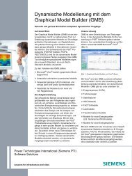
<strong>Advanced</strong> <strong>NDE</strong> <strong>Systems</strong> <strong>for</strong><br />
<strong>Flexible</strong> <strong>Operation</strong> and<br />
Maintenance of Gas Turbine<br />
Components<br />
POWER-GEN International 2006 – Orlando, FL<br />
November 28-30, 2006<br />
Copyright © 2006 <strong>Siemens</strong> Power Generation, Inc.<br />
Copyright © <strong>Siemens</strong> AG 2006. All rights reserved.
ADVANCED <strong>NDE</strong> SYSTEMS FOR FLEXIBLE OPERATION AND MAINTENANCE OF<br />
GAS TURBINE COMPONENTS<br />
Paul J. Zombo, Robert E. Shannon<br />
<strong>Siemens</strong> Power Generation, Inc. – 4400 N. Alafaya Trail, Orlando, FL 32826<br />
ABSTRACT<br />
Hot section parts in today’s gas turbines have to withstand extreme thermal and<br />
mechanical loads and management of their inspection and replacement cycles requires<br />
effective use of advanced nondestructive evaluation (<strong>NDE</strong>) and monitoring<br />
technologies. Lower temperature rotating and critical stationary parts, designed <strong>for</strong> the<br />
full life of the unit, also require effective use of <strong>NDE</strong> technologies to provide<br />
opportunities to extend unit life. To assure long component life and highest quality of<br />
these parts, a broad spectrum of <strong>NDE</strong> technologies are used in manufacturing and<br />
service. <strong>Siemens</strong> maintains a strong pursuit <strong>for</strong> the development of new and advanced<br />
<strong>NDE</strong> technologies: Examples include fast and full field inspections allow <strong>for</strong> an<br />
inspection of per<strong>for</strong>mance critical areas of the parts, including coating condition and<br />
through-coating measurements to speed up inspections. Modern imaging methods are<br />
being increasingly employed side-by-side with high-accuracy measurements of critical<br />
material parameters as advanced <strong>NDE</strong> methods.<br />
This presentation will provide an overview of advanced <strong>NDE</strong> systems recently brought<br />
into production and service operations at <strong>Siemens</strong> Power Generation with examples<br />
such as active thermography, advanced optical equipment, and on-line monitoring<br />
systems. The use of these and other advanced <strong>NDE</strong> technologies will be summarized<br />
in a strategy <strong>for</strong> assessing the condition of critical components and overall improvement<br />
in flexible gas turbine operations and effective planning <strong>for</strong> service activities.<br />
INTRODUCTION<br />
In addition to the goals described in the abstract, a high priority aspect of our advanced<br />
nondestructive evaluation (<strong>NDE</strong>) development strategy is to provide technology-based<br />
innovations that are environmentally responsible. Our most recent developments<br />
include <strong>NDE</strong> solutions which have the potential to reduce the dependence on<br />
hazardous chemical processes <strong>for</strong> stripping coatings just to provide <strong>for</strong> inspectable<br />
surface conditions required by traditional <strong>NDE</strong> methods. Also, by fully developing some<br />
of these advanced <strong>NDE</strong> methods, there is the potential to replace the need <strong>for</strong> surface<br />
<strong>NDE</strong> techniques which require the use and proper disposal of consumable materials.<br />
The overall goal is to provide the most responsive source of technology-based solutions<br />
to enable our customers to improve operating plant competitiveness and profitability.<br />
Our strategy involves a multi-pronged approach in terms of local focus and range of<br />
<strong>NDE</strong> technology innovations. The multi-pronged focus includes continued improvement<br />
of classical <strong>NDE</strong> methods, such as ultrasonics, eddy current, radiography and others.<br />
Copyright © 2006 <strong>Siemens</strong> Power Generation, Inc.
These technologies are well-established in our supply network, in-house manufacturing<br />
factories, and repair network as an integral part of commitment to provide high quality<br />
components and systems <strong>for</strong> our gas turbine, steam turbine and generator products.<br />
Some of our most advanced applications in these classical <strong>NDE</strong> methods are integrated<br />
with highly engineered portable and remote tooling serving as a backbone of all field<br />
service operations. These include continually developing new <strong>NDE</strong> probing<br />
techniques and advanced signal processing methods in support of advancing the use of<br />
<strong>NDE</strong> technologies <strong>for</strong> component life-assessment.<br />
This paper concentrates on another strategic focus, where we go beyond <strong>NDE</strong> probe<br />
improvements and are pioneering the next generation of life-assessment technologies.<br />
We draw upon a global network of <strong>Siemens</strong> engineers and scientists, and draw from<br />
other industries where <strong>Siemens</strong> has best-in-class technologies. These include<br />
emerging sensor technologies, visible light and infrared imaging technologies, threedimensional<br />
digital radiography, advanced optics, automated image processing and<br />
pattern recognition techniques, and global electronic network expertise. This strategy<br />
has led to the recent development of three new advanced <strong>NDE</strong> systems recently<br />
brought into production and service operations: SIEMAT® acoustic thermography, the<br />
Global Inspection System, an advanced optical blade and vane scanning systems <strong>for</strong><br />
automated visual inspection, and the On-Line Monitoring System, an infrared blade<br />
imaging system.<br />
INTEGRATED <strong>NDE</strong> STRATEGY<br />
Our approach is designed to go well beyond the end of the twentieth century notion of<br />
advancing <strong>NDE</strong> technologies by focusing on new probe development and trans<strong>for</strong>ming<br />
analog display techniques into digital <strong>for</strong>mats. Analysis of market trends, technology<br />
trends, and most especially customer needs in the context of <strong>NDE</strong> and power<br />
generation component monitoring leads to a number of important conclusions.<br />
Market trends show global access to knowledge-based solutions is the over-riding<br />
business need. <strong>NDE</strong> technologies provide an essential lead role because their quick<br />
and highly product-specific assessment of service-exposed conditions are absolutely<br />
necessary <strong>for</strong> maintenance, repair and replacement planning, supply network<br />
coordination, and as feedback to life-cycle design engineering and <strong>for</strong>ward-looking<br />
system per<strong>for</strong>mance strategies.<br />
Technology trends in the areas of sensors and monitoring show a number of simple, but<br />
important points to consider in finding new direction <strong>for</strong> <strong>NDE</strong> development First it is<br />
important to remember that visual inspection is the most effective overall <strong>NDE</strong> method<br />
and <strong>for</strong>ms the basis <strong>for</strong> all other <strong>NDE</strong> and monitoring methods. It is what we as humans<br />
rely on the most to gain a quick, accurate, and most-reliable assessment of conditions<br />
important to predicting what will happen next. We all know that “seeing is believing” and<br />
“a picture is worth a thousand words.” This last point is <strong>for</strong>tunate, because looking<br />
closely at technologies trends it is evident that digital imaging technology is in a period<br />
of explosive growth. Digital imaging devices and system are becoming more and more<br />
Copyright © 2006 <strong>Siemens</strong> Power Generation, Inc.
available <strong>for</strong> use in virtually all ranges of the electromagnetic spectrum, and the<br />
processing of digital images are commonly used not just in two-dimensional <strong>for</strong>mats, but<br />
increasingly in three-dimensional <strong>for</strong>mats – at least in the entertainment and video<br />
game business and in military applications. And <strong>for</strong> now it looks like we can rely on<br />
Moore’s Law to continue to provide the advantage of speeding up process times and<br />
lowering costs <strong>for</strong> digital processing and storage.<br />
Most importantly is to recognize that engineering departments have fully integrated<br />
three-dimensional modeling, process analysis and fabrication control, but not <strong>NDE</strong><br />
processes, into a well-integrated set of electronic design and manufacturing tools. That<br />
is, the integration of modern engineering tools is moving along well, all except <strong>for</strong> <strong>NDE</strong><br />
processes. As a result, in the area where <strong>NDE</strong> is of greatest benefit – providing real-life<br />
feedback of component conditions – there is a significant technology gap.<br />
<strong>Siemens</strong> Power Generation has implemented a strategy to fill this gap and to provide <strong>for</strong><br />
the integration of advanced <strong>NDE</strong> and monitoring technologies into the modern<br />
engineering toolbox. This involves a number of elements:<br />
• Implement image-based <strong>NDE</strong> applications<br />
• Develop a plat<strong>for</strong>m <strong>for</strong> 3D <strong>NDE</strong> data fusion<br />
• Make the link between <strong>NDE</strong> and design models<br />
• Implement digital image-based service plat<strong>for</strong>ms<br />
• Invest in technologies that provide rapid design validation<br />
• Emphasize sensors that are model-based<br />
A strategy <strong>for</strong> development of advanced <strong>NDE</strong> technologies must go beyond <strong>NDE</strong> probe<br />
improvement and meet strategy elements important to power generation industry.<br />
Figure 1 shows a table where these strategic elements are listed to compare with a<br />
number of advanced <strong>NDE</strong>-related technologies. The table’s matrix shows an analysis<br />
of which technologies we are currently developing and have plans to accelerated<br />
development in the future to address the strategic need elements.<br />
ADVANCED <strong>NDE</strong> TECHNOLOGY SOLUTIONS<br />
As a result of development activities in <strong>Siemens</strong> Power Generation, three advanced<br />
<strong>NDE</strong> technologies are highlighted because they are currently being integrated into our<br />
gas turbine products and services. They are:<br />
1. Global Inspection System – using combined 2-D and 3D digital imaging of blades<br />
and vanes;<br />
2. SIEMAT® sonic infrared – using ultrasonic vibrations and infrared imaging <strong>for</strong><br />
imaging <strong>for</strong> crack on coated and uncoated parts;<br />
3. On-Line Monitor – using high-speed infrared <strong>for</strong> imaging blades during at power,<br />
full speed operation.<br />
Copyright © 2006 <strong>Siemens</strong> Power Generation, Inc.
Figure 1 – Value assessment and development priorities of advanced <strong>NDE</strong><br />
technologies to meet power generation industry strategic needs.<br />
Global Inspections System<br />
The Global Inspection System is a new <strong>NDE</strong> technology concept, illustrated in Figure 2,<br />
developed by expanding upon known dimensional and visual inspection techniques and<br />
integrating nondestructive inspection in<strong>for</strong>mation with a three-dimensional model of a<br />
component to provide a novel capability <strong>for</strong> true virtual space inspection.<br />
We have recently developed a hardware/software system, shown in Figure 3, that<br />
combines two dimensional visual inspection data with three dimensional surface<br />
position inspection data to map acquired 2D optical images onto viewed surfaces of a<br />
3D digital model of gas turbine blades and some vanes at this time. The result is a true<br />
virtual 3D image of the real component, including optical images of degradations,<br />
defects, distortion and other conditions observable during a visual inspection. Once the<br />
virtual component is created in virtual space, a human inspector can manipulate the<br />
virtual component to per<strong>for</strong>m a visual inspection of the virtual component. The results<br />
of such an inspection can be recorded in the virtual space, including marking directly<br />
onto the virtual part. The inspector can per<strong>for</strong>m the virtual inspection to include<br />
manipulations that are commonly accomplished during a manual visual inspection of the<br />
real component. In addition, the system permits the inspector to enhance the<br />
inspection, such as with zoom imaging, hue, saturation and/or luminance manipulation.<br />
The system also permits layering of additional <strong>for</strong>ms of inspection data and evaluation<br />
results onto the virtual component, addition of automatic evaluation techniques, and<br />
other data enhancement, data comparison, and statistical analysis techniques.<br />
Copyright © 2006 <strong>Siemens</strong> Power Generation, Inc.
Figure 2 – Working principle of the <strong>Siemens</strong> Global Inspection System using<br />
combined 2-D and 3D digital imaging of blades and vanes<br />
Most importantly the system provides <strong>for</strong> the 3D files of the virtual component to be<br />
archived <strong>for</strong> later comparison with similar in<strong>for</strong>mation <strong>for</strong> the same component at a point<br />
in time later in the component's life after the original component condition has been<br />
changed, or <strong>for</strong> comparison with similar in<strong>for</strong>mation <strong>for</strong> other similar components. This<br />
allows the results of the inspections (i.e. component condition assessments) that are<br />
created by the human inspector using the inspector's training and experience, combined<br />
with graphical user interface (GUI) image processing operations or automated image<br />
processing operations, to be recorded as additional surface mapping features on the<br />
virtual 3D image of the real component rather than as a disconnected piece of paper or<br />
reduced to tablular data points or rough sketch in<strong>for</strong>mation in disconnected files.<br />
This allows <strong>for</strong> inspection results to be archived and recalled <strong>for</strong> various comparisons, to<br />
track condition assessment changes through the partial or entire life-cycle of a<br />
component or a population of components, and <strong>for</strong> the comparison of various<br />
components or groups of components with design, operational, service and repair<br />
history data.<br />
SIEMAT ® Acoustic Thermography<br />
The advanced <strong>NDE</strong> method called SIEMAT ® Acoustic Thermography (or Sonic IR by<br />
some) involves exciting the object to be inspected with sufficient ultrasonic energy to<br />
cause the cracks themselves to produce heat, as illustrated in Figure 4. Typically, only<br />
sufficient energy to produce a short (0.1 to 1.0 second) heat pulse of a few degrees<br />
centigrade is used, sufficient enough to be detected using available, high-speed, highsensitivity<br />
infrared (IR) imaging systems, but not so much vibration energy to cause any<br />
damage to the component.<br />
Copyright © 2006 <strong>Siemens</strong> Power Generation, Inc.
Figure 3 – <strong>Siemens</strong> Global Inspection hardware/software system <strong>for</strong> blades<br />
Development of the SIEMAT ® acoustic thermography method has resulted in processes<br />
that are used on a variety of gas turbine products. Practical processes are available <strong>for</strong><br />
<strong>NDE</strong> inspections of turbine blades, turbine vanes and transitions. Inspection of the<br />
entire area of the hot gas exposed surfaces of a blade is accomplished in one shot<br />
lasting lest than two seconds on one side (suction side) and a second shot lasting less<br />
than two seconds on the other side (pressure side). Analysis using special thermal<br />
imaging processing software allows the real-time or later off-lie viewing of any heatpulse<br />
indications that stand out against the ambient temperature background to indicate<br />
the presence of cracks. The basic process of vibrating a component with a variety of<br />
ultrasonic frequencies has been demonstrated to be especially effective at detecting<br />
very tight cracks. Experience shows in some cases these cracks may not be reliably<br />
detected by other more traditional <strong>NDE</strong> techniques. Even the smallest cracks can be<br />
expected to generate some heat when vibrated sufficiently, so there are a wide variety<br />
of techniques that can be implemented by selecting the appropriate vibration excitation<br />
parameters and thermal imaging optics.<br />
Because the vibrations are supported by the base metal structure of the components,<br />
they are produced regardless of whether the component is coated or not. The heat<br />
pulses are very short duration and can diffuse through coatings, such as MCrAlY or<br />
thermal barrier coatings (TBCs) sufficiently to be recorded discretely by high speed<br />
infrared imaging systems. In some cases special image processing software designed<br />
using thermal signal behavior known from physics or discovered during research in the<br />
SIEMAT® acoustic thermography method is required to aid the <strong>NDE</strong> operator. The<br />
application of the various image processing options, playback of the time-varying<br />
thermal images and highlighting of thermal image indications is implemented with<br />
Copyright © 2006 <strong>Siemens</strong> Power Generation, Inc.
specifically designed graphical user interfaces in the SIEMAT® acoustic thermography<br />
systems.<br />
Figure 4 – Full-field inspection <strong>for</strong> cracks using SIEMAT® acoustic thermography<br />
<strong>Siemens</strong> Power Generation has extensive experience with Sonic IR techniques. Our<br />
developments include over six years of research and development, leading to<br />
implementation of the new <strong>NDE</strong> tools <strong>for</strong> inspection and diagnostics of power<br />
generation components, shown in Figure 5. These new technologies have been<br />
integrated into <strong>Siemens</strong> product lines under the SIEMAT ® acoustic thermography label.<br />
We have developed advanced expertise in the critical Sonic IR process parameters,<br />
including vibration excitation, infrared imaging and image capture, image processing,<br />
hardware/software systems integration and evaluation of the results in the context of<br />
component design, manufacturing condition and degradation from exposure to service<br />
conditions.<br />
The on-going objectives <strong>for</strong> future advancement of SIEMAT® acoustic thermography<br />
technology are being directed to provide a significant positive impact to the<br />
environment. As a result of successful demonstrations of the capability of the method to<br />
detect cracks in all locations of coated components, we believe SIEMAT® acoustic<br />
thermography will be preferred on components that are currently inspected using dye<br />
penetrants with the same or greater reliability and sensitivity. This will create a<br />
significantly positive benefit by replacing the current chemical-intensive inspection<br />
processes and eliminate the environmental hazards associated with paint stripping by<br />
utilizing a mechanical inspection capability.<br />
Copyright © 2006 <strong>Siemens</strong> Power Generation, Inc.
Figure 5 – SIEMAT ® acoustic thermography systems are available <strong>for</strong> global<br />
support of gas turbine products and services<br />
Because SIEMAT ® acoustic thermography is an image-based inspections technology,<br />
the inspection “data” and results are ready <strong>for</strong> direct integration with the Global<br />
Inspection System 2D-3D archive files. The structure of the Global Inspection System<br />
2D files mapped as a surface skins or layers on the underlying 3D solid model leads to<br />
a number of significant advantages. Life assessment analysis strategies rely<br />
extensively on the integration of all in<strong>for</strong>mation available about component conditions<br />
and history. Modern design engineering technologies are based on solid model<br />
analysis, so the analysis of <strong>NDE</strong> inspection results directly on the actual, as measured<br />
solid model of the component is the right approach <strong>for</strong> integration into design<br />
engineering processes. Figure 6 shows how SIEMAT® crack indications (on the left)<br />
are displayed and analyzed along with visual inspection images and dimensional data.<br />
More complex and clearly more reliable diagnostics of fleet diagnostics and prognostics<br />
of components classes are being developed by using this standardized inspection data<br />
archiving and analysis system. Statistical analysis of fleet data and life-cycle inspection<br />
data will result in more profound technology-based life-assessment engineering<br />
solutions.<br />
On-Line Monitor Technology<br />
The third advanced <strong>NDE</strong> technology, On-Line Monitor, is a breakthrough in terms of<br />
pushing inspection of components to a true on-line assessment solution <strong>for</strong> critical gas<br />
turbine components. Usually, <strong>NDE</strong> solutions provide value after unit shut-down or<br />
disassembly when traditional <strong>NDE</strong> inspections can be effectively per<strong>for</strong>med.<br />
Additionally, <strong>for</strong> most hot-section components in a gas turbine, complete inspection of<br />
the metallic structure of components, such as blade, vanes and transitions, have to wait<br />
until the coatings are removed. This presents significant limitations to the task of<br />
gathering and assessing in<strong>for</strong>mation needed <strong>for</strong> life-assessment programs in support of<br />
flexible operation and maintenance. The process of stripping coatings is timeconsuming,<br />
expensive and involves the use of aggressive chemicals that are a potential<br />
Copyright © 2006 <strong>Siemens</strong> Power Generation, Inc.
threat to the environment, requiring additional costs and risks in proper handling and<br />
disposal. Also, the stripping process itself is aggressive enough that the condition of<br />
the underlying metals are significantly altered, especially the size and morphology of the<br />
very degradations that are the object of the <strong>NDE</strong> inspections. The previous discussed<br />
technologies, <strong>for</strong> example SIEMAT® acoustic thermography, are a solution to these<br />
reliability and environment issues, but there is a delay in the availability of assessment<br />
results from off-line <strong>NDE</strong> inspections and additional in<strong>for</strong>mation management is required<br />
to correlate results to the actual operating conditions. The advantages are obvious in<br />
being able to inspect or monitor critical components, not only in the gas turbine be<strong>for</strong>e<br />
disassembly, but while it is actually operating. And there is an additional advantage to<br />
be able to directly monitor the effects on critical component per<strong>for</strong>mance when actually<br />
making changes to operation conditions, such as power changes.<br />
Figure 6 – Images of SIEMAT ® crack indications are ready <strong>for</strong> fusion with the<br />
component’s Global Inspection System inspection archives<br />
The first On-Line Monitor <strong>Systems</strong> were designed to image row 1 and row 2 blades<br />
during operation, while they are moving at full-speed, 3600 rpm. The blade sensor<br />
uses high-speed thermal imaging and computer recognition software to thermally<br />
examine each blade as it passes a focal plane array sensor. With the use of highspeed<br />
sensor arrays, the aspects of spatial resolution related to using an array are<br />
considered, and the full field two-dimensional images provide substantially more robust<br />
data sets of the blades thermal conditions compared with single-point pyrometer<br />
readings. Operating conditions that the sensor is subject to in the turbine engine are<br />
accounted <strong>for</strong> in the design. A turbine case penetration system is design to place the<br />
sensor optics in the pressure chamber of the engine turbine section, as illustrated in<br />
Figure 7.<br />
The sensor selection is based on the best combination of reliability, robustness and<br />
sensitivity. Infrared instrumentation is selected to operate at some optimum spectral<br />
response within the infrared band of 0.09 – 12.0 µm. Very short integration times, on<br />
the order of a millisecond or less are required to get the “snap-shots” of blades moving<br />
Copyright © 2006 <strong>Siemens</strong> Power Generation, Inc.
through the viewing window at greater than the speed of sound. Additionally, the<br />
system includes design considerations <strong>for</strong> resolution, array size, sensor cooling, power<br />
dissipation, dynamic range, package size, thermal stability, vibration resistance, and of<br />
course cost. Infrared camera and support systems have been operated in test-bed and<br />
operating plant environments and have demonstrated integrity of the system <strong>for</strong> 8000<br />
hours of engine operation.<br />
Figure 7 – Example of penetration <strong>for</strong> on-line thermal imaging of row 1 turbine<br />
blades<br />
The On-Line Monitor supervisory control software, shown in Figure 8, includes the<br />
ability to control sensor parameters and synchronize the image timing to the rotation of<br />
the gas turbine shaft, such that individual blades can be selected <strong>for</strong> instantaneous or<br />
continuous monitoring. The software operates in a PC environment and can be brought<br />
to the customer plant site to be connected directly to the installed optical system.<br />
Alternatively, the control signal and resulting image outputs can be streamed through<br />
internet connections so that the On-Line Monitor can be operated remotely, from<br />
<strong>Siemens</strong> service support locations, such as the Orlando Power Diagnostic Center.<br />
Figure 8 – On-Line Monitor software controls the real-time, high-speed IR sensor<br />
to capture turbine images on-site or from <strong>Siemens</strong> Power Diagnostics Center.<br />
Copyright © 2006 <strong>Siemens</strong> Power Generation, Inc.
Extensive testing of the On-Line Monitor System has been completed <strong>for</strong> imaging<br />
blades during power operation. The initial component life-assessment target <strong>for</strong> the<br />
system was to be able to detect, measure and monitor the growth of TBC defects,<br />
should they occur in operation. The upper left, bottom left and bottom center images in<br />
Figure 9 shows some examples images made of test samples that were operated in<br />
W501F engines <strong>for</strong> the purpose of qualifying the On-Line Monitor System. In the<br />
process, the system has proven to be very sensitive to a wide range of turbine blade<br />
operation conditions. Such changing conditions as cooling hole blockage, plat<strong>for</strong>m<br />
rubs, cooling hole per<strong>for</strong>mance, and TBC thickness result in images that change<br />
dynamically when monitored during plant operation and during load changes.<br />
Figure 9 – On-Line Monitor images operating features and service conditions of<br />
row 1 or 2 gas turbine blades while operating at power and 3600 rpm.<br />
This new class of inspection and monitoring in<strong>for</strong>mation is leading to new engineering<br />
methods <strong>for</strong> validation of component designs. The On-Line Monitoring images, as<br />
shown in Figure 9 and top left of Figure 10, are two-dimensional radiance maps of the<br />
blades as they are viewed by the imaging system. Work is ongoing to design additional<br />
features into the system, including software analysis of the signal contents to calibrate<br />
the images <strong>for</strong> analysis as surface temperature maps. Figure 10 shows an example of<br />
the conversion of the On-Line Monitor images into surface temperature maps. Each<br />
color in the resulting image constructed from the radiance map data represents a 20°C<br />
isotherm.<br />
Copyright © 2006 <strong>Siemens</strong> Power Generation, Inc.
Figure 10 – On-line imaging of blade surface temperature at 20°C isotherms<br />
CONCLUSIONS<br />
A strategy <strong>for</strong> the integrated development of advanced <strong>NDE</strong> technologies has<br />
successfully led to three new technical solutions <strong>for</strong> effective life-assessment of gas<br />
turbine components. The combined 2D-3D blade and vane imaging system embodied<br />
in the Global Inspection system provides a plat<strong>for</strong>m <strong>for</strong> the collection, archiving and<br />
analysis of inspection data. This plat<strong>for</strong>m is a pioneering step towards integrating <strong>NDE</strong><br />
technology with modern design engineering tools. The SIEMAT ® acoustic<br />
thermography method, with factory, repair depot and field-portable systems, is a key<br />
technology solution <strong>for</strong> improved inspection of coated components, and rapid full-field<br />
inspection of components without waiting <strong>for</strong> delicate, detailed scanning systems.<br />
An even more <strong>for</strong>ward-looking <strong>NDE</strong> technology is now available in the On-Line<br />
Monitoring System which allow <strong>for</strong> the direct assessment of critical internal components.<br />
There simply is no equivalent alternative solution to the advantages of the On-Line<br />
Monitor <strong>for</strong> validation of engineering designs and real-time assessment of operational<br />
factors <strong>for</strong> hot section components, such as turbine blades and vanes. This technology<br />
has been fully demonstrated <strong>for</strong> per<strong>for</strong>ming these assessments even while blades are<br />
running inside the gas turbine at 3600 rpm and full power.<br />
These global inspection solutions <strong>for</strong>m an integrated approach to developing advanced<br />
<strong>NDE</strong> technologies, that rely on multi-mode inspections and data analysis and link<br />
readily with CAD-based engineering design systems. They provide a new pioneering<br />
approach to predictive maintenance and extending life in critical gas turbine<br />
components.<br />
The content of this paper is copyrighted by <strong>Siemens</strong> Power Generation, Inc. and is licensed to PennWell<br />
<strong>for</strong> publication and distribution only. Any inquiries regarding permission to use the content of this paper, in<br />
whole or in part, <strong>for</strong> any purpose must be addressed to <strong>Siemens</strong> Power Generation, Inc. directly.<br />
Copyright © 2006 <strong>Siemens</strong> Power Generation, Inc.