

The Evolution of Gear Spindles - Emerson Industrial Automation
The Evolution of Gear Spindles - Emerson Industrial Automation
The Evolution of Gear Spindles - Emerson Industrial Automation

Create successful ePaper yourself
Turn your PDF publications into a flip-book with our unique Google optimized e-Paper software.
Proceedings <strong>of</strong> DETC2000<br />
2000 ASME Design Engineering Technical Conference<br />
September 10-13, 2000, Baltimore, Maryland, USA<br />
DETC2000/PTG14454<br />
THE EVOLUTION OF GEAR SPINDLES<br />
Jon R. Mancuso<br />
Engineering Manager<br />
Kop-Flex, <strong>Emerson</strong> Power Transmission Corp.<br />
Joe Zilberman<br />
Manager Research<br />
Kop-Flex, <strong>Emerson</strong> Power Transmission Corp.<br />
ABSTRACT<br />
<strong>Gear</strong> spindles were first applied to rolling mills in the early<br />
1950’s. Over this time the basic design has remained constant<br />
except for the material used and the hardening process. And<br />
today they are still the most commonly used drive for rolling<br />
mills. This is because they are power dense (handle the highest<br />
torque for a given Outside Diameter), easy to maintain and<br />
economical. New processes have been developed for grinding<br />
carburized gear spindles to optimize tooth contact thereby<br />
increasing spindle capacity and life by 30-100%. This process<br />
allows for a more compact design (usually one size smaller)<br />
along with improved life.<br />
INTRODUCTION<br />
Prior to the 50s wobblers and slipper spindles (see Figure 1 &<br />
2) were primarily used in steel mills. During the 50’s gear<br />
spindles were first applied to hot rolling and cold mills. Over<br />
the years the basic design has remained constant, but there have<br />
been many features incorporated into the design and several<br />
changes in how they are optimized, analyzed, and made.<br />
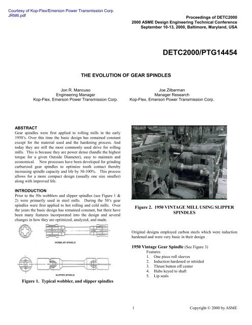
Figure 2. 1950 VINTAGE MILL USING SLIPPER<br />
SPINDLES<br />
Original designs employed carbon steels which were induction<br />
hardened and were very basic in their design<br />
Figure 1. Typical wobbler, and slipper spindles<br />
1950 Vintage <strong>Gear</strong> Spindle (See Figure 3)<br />
Features<br />
1. One piece roll sleeves<br />
2. Induction hardened or nitrided<br />
3. Thrust button <strong>of</strong>f center<br />
4. Hubs keyed to shaft<br />
5. Lip seals<br />
1 Copyright © 2000 by ASME
Figure 3. 1950 Vintage <strong>Gear</strong> Spindle<br />
Today’s gears spindles incorporate many features to<br />
accommodate the higher power, smaller diameters, easily<br />
maintainable improved life, higher misalignment with higher<br />
reliability.<br />
.<br />
2000 Vintage <strong>Gear</strong> Spindle (see Figure 4 & 5)<br />
Features<br />
1. Usually replaceable gear element unless OD<br />
restricted – for ease <strong>of</strong> replacement and at<br />
economical cost.<br />
2. Nitrided or corrected carburized gear element –<br />
for longer life.<br />
3. Thrust Button on center – for optimum wear life.<br />
4. Hubs splined to shaft - to maximize torque.<br />
5. Rising rings seals – to keep lube in and rolling<br />
solutions out.<br />
6. Piloted roll end pods – for lower wear.<br />
Figure 5. 2000 VINTAGE HOT STRIP MILL USING<br />
GEAR SPINDLES<br />
Nitriding vs Carburizing<br />
Today most gear spindles are either nitrided or carburized. For<br />
reduced distortion, Nitriding is used. Nitriding provides a hard<br />
case which range from Rc 55/64 and with very little distortion.<br />
<strong>The</strong> case depth ranges from 0.015” to 0.030” (0.38-0.76mm).<br />
This process is good for fine pitch gearing in bar, rod and cold<br />
mills. For roughing mill and hot strip mill spindles with course<br />
pitch teeth a deeper case is required. <strong>The</strong>se spindles employ<br />
carburized gearing which produces deep cases 0.060” to 0.250”<br />
(1.5-6.4mm) and a hardness <strong>of</strong> Rc 55/62. Again like induction<br />
hardening during the quench operation, distortion occurs to the<br />
actual tooth and also pitch diameter.<br />
During operation, gear spindles are subject to high<br />
misalignment. At 2 degrees only 40% <strong>of</strong> the teeth carry the<br />
load. <strong>The</strong> limited number <strong>of</strong> teeth carrying the load combined<br />
with the distortion, resulting from carburizing, causes some<br />
teeth to be highly loaded. This results in subsurface shear and<br />
spalling. <strong>The</strong> results <strong>of</strong> this distortion (if uncorrected) shows up<br />
as areas <strong>of</strong> spalling.<br />
Figure 4. 2000 Vintage <strong>Gear</strong> Spindle<br />
2 Copyright © 2000 by ASME
How A <strong>Gear</strong> Spindle Works<br />
Most gear spindles have involute pr<strong>of</strong>iles teeth with the external<br />
teeth crowned. One must understand how a gear coupling<br />
works in-order to understand why distortion, material,<br />
lubrication, misalignment and lubrication are critical for the<br />
successful operation <strong>of</strong> spindles. When a gear coupling is<br />
misaligned (pivot position) with no load, only two teeth 90<br />
degrees from the plane <strong>of</strong> misalignment (tilt position) come into<br />
contact (see Figure 6). As a tooth is rotated 360 degrees under<br />
load, its point <strong>of</strong> contact will then move along the tooth in a<br />
hour glass pattern (see figure 7). Depending on the load, teeth<br />
may not contact at the center (pivot point) and heavier pattern at<br />
the end <strong>of</strong> the pattern (the tilt position). <strong>The</strong> width <strong>of</strong> the pattern<br />
depends on what the curvature it was cut for and what the<br />
operating misalignment is. If the gear teeth are cut for 4<br />
degrees and it runs at 2 degrees one will see a sweep pattern<br />
approximately 50% <strong>of</strong> the length <strong>of</strong> the tooth.<br />
Figure 7. TOOTH LOAD SWEEP<br />
(THROUGH 360 0 )<br />
VARIOUS TOOTH FORMS (See Figure 8)<br />
Spindle teeth are usually <strong>of</strong> two forms<br />
1. Tip piloted<br />
2. Root piloted<br />
<strong>The</strong> pr<strong>of</strong>iles are usually cut for 20 or 25 degree pressure angles.<br />
FIGURE 8. VARIOUS TOOTH FORMS<br />
Figure 6. LOADING CYCLE OF GEAR COUPLING<br />
TEETH<br />
Tip piloted teeth are more common in nitrided spindles. 25<br />
degree pressure angle teeth are commonly used where teeth cut<br />
for high angles (4-6 degrees) the ends <strong>of</strong> the teeth can get pretty<br />
thin and during roll changing or even during operation the teeth<br />
can break in bending. Twenty (20) degree pressure angle teeth<br />
have a slightly sharper curvature along their pr<strong>of</strong>ile and make a<br />
sharper parabolic ball which effectively improves the rolling<br />
action and can slightly derease the coefficient <strong>of</strong> friction; this<br />
tends to make 20 degree teeth more suited where wear is <strong>of</strong><br />
concern (high ScV). Unfortunately the right tooth design is not<br />
a precise science and which is best for which application has<br />
developed for experience. One form failed and another tried in<br />
the same application and; “success”.<br />
3 Copyright © 2000 by ASME
MATERIALS<br />
<strong>The</strong>re are various materials used in gear spindles. <strong>The</strong><br />
physical properties <strong>of</strong> a gear spindle depends on the material,<br />
the heat treatment, and the process used to shape teeth after heat<br />
treatment. Many alloys are used to make spindles, each with its<br />
own inherent core strength and other properties. Manufactures<br />
then usually harden the teeth to increase wear resistance and<br />
strength, using either induction hardening, nitriding, or<br />
carburizing. <strong>The</strong> effects <strong>of</strong> each type <strong>of</strong> heat treatment differ<br />
for each alloy. One material and heat treatment is not best for<br />
all applications. <strong>The</strong>re are three things that one must evaluate,<br />
Strength (see Table 1), Wear (see Table 2), and ScV (see Table<br />
4). <strong>The</strong> tables below compare these properties for various<br />
materials, heat treatment and also the type <strong>of</strong> lubrication<br />
Strength Hierarchy <strong>of</strong> <strong>Gear</strong> Coupling Materials<br />
Material Minimum<br />
Hardness<br />
Relative<br />
Strength<br />
(BHN)<br />
3310 Carburized 360 5<br />
4320 Carburized 310 4<br />
Nitralloy N 400 3.5<br />
8620 Carburized 300 3.5<br />
4140 Fully Contoured 300 3.25<br />
Induction Hardened<br />
Nitralloy 135 320 2.75<br />
4340 Nitrided 330 2.75<br />
4140 Flank Induction 270 2.5<br />
Hardened<br />
4140 HT and 310 2.5<br />
Nitrided<br />
1035/1045 Fully 155 1.75<br />
Contoured Induction<br />
Hardened<br />
1035/1045 Induction 155 1<br />
Hardened<br />
1035/1045 155 1<br />
Table 1. Strength Hierarchy<br />
Wear Hierarchy <strong>of</strong> <strong>Gear</strong> Coupling Materials<br />
Material Minimum<br />
Hardness<br />
Relative<br />
Strength<br />
(BHN)<br />
Nitralloy N 65 Rc 4.5<br />
Nitralloy 135 65 Rc 4.5<br />
3310 Carburized 62 Rc 3<br />
4320 Carburized 60 Rc 2.5<br />
8620 Carburized 58 Rc 2.25<br />
4140 HT and 54 Rc 2<br />
Nitrided<br />
4140 Induction 50 Rc 1.75<br />
Hardened ALL<br />
4340 Nitrided 49 Rc 1.5<br />
1035/1045 Fully ALL 45 Rc 1.5<br />
4140 Heat Treated 280-310 1.25<br />
BHN<br />
1035/1045 ALL 155 BHN 1<br />
Table 2. Wear Hierarchy<br />
ScV Limits for Materials and Lubrication<br />
This factor looks at the contact (hertzian) stress and the<br />
sliding velocity <strong>of</strong> the teeth from misalignment. It also<br />
considers the type <strong>of</strong> lubrication.<br />
Most gear spindles today are lubricated with special<br />
greases that were specially developed for spindle operation.<br />
<strong>The</strong>re are two basic types <strong>of</strong> lubricants. <strong>The</strong> lithium based<br />
grease with base oil viscosity over 150 SUS @ 210 o F, also has<br />
several additives, for water washout, handling high impact loads<br />
(molydifsulfide 5-10%), etc. <strong>The</strong> other types <strong>of</strong> lubricants used<br />
are special synthetic greases that can withstand high ScV’s seen<br />
in the latter stands <strong>of</strong> Hot Strip Mills and many Cold Mills.<br />
<strong>The</strong>se mills may operate over 500 RPM and operate at angles<br />
over 1 degree. <strong>The</strong>y will have ScV’s over 500,000 psi-ips.<br />
<strong>The</strong>re are two parts <strong>of</strong> this ScV factor<br />
1. Compressive stress (hertz stress) and tooth sliding<br />
velocity<br />
Hertz Compressive Stress (assumes a cylinder on a<br />
plane)<br />
S c = 4580<br />
x<br />
T<br />
ρ x N x PD x D c x h<br />
Where<br />
T = Torque<br />
ρ = Number<br />
N = Number <strong>of</strong> teeth<br />
PD = Pitch Diameter<br />
( lb -in)<br />
<strong>of</strong> teeth in contact<br />
( in)<br />
(%)<br />
h = Tooth engagement height (1.6/DP<br />
)<br />
(in)<br />
4 Copyright © 2000 by ASME
One <strong>of</strong> the most important factors in the design <strong>of</strong> gearing<br />
for gear couplings/spindles is the number <strong>of</strong> teeth engaged<br />
under load. This varies not only with the sleeve and hub<br />
design but also with misalignment, load, heat treatment and<br />
manufacturing process. As a rule <strong>of</strong> thumb, generally the<br />
number <strong>of</strong> teeth loaded is primarily affected by<br />
misalignment (see Table 3). <strong>The</strong> numbers are further<br />
reduced because <strong>of</strong> distortions from heat treating and other<br />
manufacturing errors. Carburizing distortions can reduce<br />
tooth loading, so only 25-50% <strong>of</strong> the number in the chart is<br />
achieved. Ground vs hob/shaped teeth may increase the<br />
number <strong>of</strong> teeth in contact by 30-50%. <strong>The</strong> design <strong>of</strong> the<br />
sleeve and hub can increase or decrease these numbers.<br />
Sleeves and hubs with thick rims may not allow the teeth to<br />
deflect under load or if to thin cause all teeth to be loaded.<br />
Having all the teeth loaded sounds good but for spindles<br />
running at high ScV having them go through a no load cycle<br />
allows the lube to squeeze through and this could allow the<br />
coupling to run cooler and may keep the lube from breaking<br />
down.<br />
Misalignment Degrees Percent <strong>of</strong> teeth in contact<br />
0 80%<br />
0.5 60%<br />
1 50%<br />
2 40%<br />
3 35%<br />
4 25%<br />
5 15%<br />
6 10%<br />
Table 3. Percent <strong>of</strong> Teeth Loaded vs Misalignment<br />
2. ScV Criteria<br />
S c V a product <strong>of</strong> Hertz stress above and the sliding<br />
velocity <strong>of</strong> the gear teeth<br />
V = π<br />
Where<br />
PD = Pitch Diameter<br />
α<br />
⎡ RPM ⎤<br />
x PD x sinα x ⎢ ⎥<br />
⎢⎣<br />
60 ⎥⎦<br />
= Operating angle<br />
(in)<br />
(degrees)<br />
(in/sec)<br />
S c = Hertz Stress @ operating angle<br />
Limits for ScV are based on the type <strong>of</strong> material, surface<br />
treatment and the type <strong>of</strong> lubrication (see Table 4)<br />
Material Lubrication ScV (psi-ips)<br />
Method<br />
Medium Carbon Grease 125,000-175,000<br />
Steel AISI 1032-1045<br />
Alloy Steel (280-310 Continuously 175,000-225,000<br />
BHN)<br />
Lubricated<br />
Alloy Steel (280-310 Grease 200,000-300,000<br />
BHN)<br />
AISI 4140 (nitrided) Continuously 200,000-300,000<br />
Lubricated<br />
AISI 4140 (nitrided) Grease 400,000-600,000<br />
AISI 8620/4320 Grease 300,000-400,000<br />
(Carburized)<br />
AISI 3310<br />
Grease 400,000-500,000<br />
(Carburized)<br />
Nitralloy 135 & N<br />
(Nitrided)<br />
Grease 1,000,000-1,200,000<br />
Table 4. ScV Criteria<br />
NITRIDED SPINDLES.<br />
Nitrided gear spindles are commonly used in bar mills, cold<br />
mills and some finishing stand in hot strip mills. This surface<br />
finish provides good wear resistance. <strong>The</strong> harder a surface is,<br />
the more it resists wear. 500 BHN (52 Rc) is approximately<br />
three times more wear resistant than 200 BHN, but 600 BHN is<br />
approximately twice as resistant as 500 BHN,<br />
CARBURIZED SPINDLES<br />
One method <strong>of</strong> correcting this distortion is lapping; the<br />
“rubbing” <strong>of</strong> the external tooth with the internal tooth using an<br />
abrasive medium to “wear the parts in” or remove the high<br />
spots. <strong>The</strong> difficulty here is that the parts are lapped in matched<br />
sets, If they are mismatched the tooth contact will be reduced<br />
and may be greater than if it was not lapped. One approach to<br />
minimize poor contact from a possible mismatch is to index lap<br />
the parts. This improves the contact if mismatched but does not<br />
produce the best contact..<br />
Several years ago, the existing tooth forms and limitation <strong>of</strong><br />
grinding equipment prevented gear spindle teeth from being<br />
ground after carburizing. With the advent <strong>of</strong> the compact hot<br />
strip mill came the need for higher angles and power with<br />
smaller spindles. A patented tooth form and process for grinding<br />
carburized gear spindles to optimize tooth contact was<br />
developed to meet these new requirements. This design and<br />
process corrects carburized tooth distortion in the internal and<br />
external gear tooth flanks. This gearing has been in service in<br />
one application for over three years where the teeth still have a<br />
mirror finish. It also has been used in other application with<br />
similar results.<br />
5 Copyright © 2000 by ASME
This gearing provides the following features<br />
1. Ground to AGMA 10-11 for improved wear life and<br />
reduced tooth spalling<br />
2. A unique process and tooth design that reduces tensile<br />
stress due to grinding<br />
3. Grinding increases the number <strong>of</strong> teeth in contact, resulting<br />
in longer operating life<br />
4. More teeth in contact equals greater torque capacity,<br />
smaller spindles and larger service factors<br />
Below are pictures <strong>of</strong> carburized spindle<br />
Figure 9. Uncorrected<br />
Figure 10. Lapped<br />
Figure 11. Ground<br />
BLUE CONTACT PATTERN<br />
AFTER 3 YR OF OPERATION<br />
Figure 11. CARBURIZED AND GROUND GEARING<br />
(CGG)<br />
OTHER ADVANCES IN THE TECHNOLGY USED<br />
IN GEAR SPINDLES<br />
Today FEA analysis is used in the design <strong>of</strong> critical components<br />
for gear spindles.<br />
BLUE PATTERN<br />
AFTER ONE YR OF OPERATION<br />
FIGURE 9. AS CARBURIZED GEARING<br />
In one application the customer wanted the pinion sleeves (see<br />
Figure 12 & 13) to have a very heavy shrink 0.003/in <strong>of</strong><br />
diameter. <strong>The</strong>se spindles had a replaceable gear ring (see<br />
Figure 14). It is important to assure that these gear rings are<br />
properly supported or the intermediate sleeve can rock during<br />
operation and cause excessive wear <strong>of</strong> the teeth or splines. A<br />
FEA analysis and 1/8 scale model were done and it was<br />
determined that the pilots, front and back <strong>of</strong> the intermediate<br />
sleeve had to be designed differently. <strong>The</strong> front pilot grew<br />
(0.048”) but the back pilot actually collapsed (0.009”). This<br />
would have made assembly very difficult. <strong>The</strong> picture above <strong>of</strong><br />
the CGG after 3 years demonstrates that this gear is properly<br />
loaded.<br />
BLUE CONTACT PATTERN<br />
AFTER 1 YR OF OPERATION<br />
FIGURE 10. CARBURIZED AND LAPPED<br />
GEARING<br />
6 Copyright © 2000 by ASME
FEA models can also be used to better predict the load patterns<br />
<strong>of</strong> the gear teeth (see Figure 15A,B, C) . This analysis is very<br />
complicated and is used to optimize tooth shapes. Further work<br />
in analyzing tooth loading is on going Since there are many<br />
variables in the design <strong>of</strong> gear spindles one still must rely on<br />
conventential analysis and experience factors to design,<br />
optimize and predict life.<br />
Figure 12. FEA Model <strong>of</strong> Pinion Sleeve<br />
A.<br />
Figure 13. Pinion Sleeve<br />
B.<br />
C.<br />
FIGURE 15. TOOTH LOADING OF GEARING<br />
Figure 14. <strong>Gear</strong> spindle pinion end with intermediate<br />
Sleeve<br />
7 Copyright © 2000 by ASME
FEA is also used to evaluate failures and improve designs.<br />
Normally when a cobble in a mill occurs the roll neck will snap<br />
or the shaft in the spindle will shear? One customer was<br />
experiencing repetitive failure <strong>of</strong> roll sleeves (see Figure 16).<br />
Examination <strong>of</strong> the failure indicated that failure was initiated<br />
near a lube fitting in this sleeve. A model (see Figure 17) was<br />
run and the failure mode and path <strong>of</strong> the crack was predicted<br />
(see Figure 18 A & B). Further analysis was done to reposition<br />
the lube fitting further back in the roll sleeve. This increased<br />
the safety margin be 50%. Eventually the lube fitting was<br />
eliminated in the roll sleeve totally. Lubrication fittings were<br />
put into the shaft. This not only eliminated the roll failures but<br />
also positioned the fitting so it was more accessible thereby<br />
assuring it would get lubricated.<br />
Figure 18 A & B. Failure Mode Prediction<br />
Figure 16. Roll Sleeve<br />
Conclusions<br />
<strong>Gear</strong> spindles continue to be the most common spindle<br />
used on main drive mills. <strong>The</strong>y are very power dense and if<br />
properly maintained they can provide in-excess <strong>of</strong> three years <strong>of</strong><br />
life before there gear elements need to be replaced. It is also<br />
expected that further improvements in analysis, materials and<br />
process will allow the gear spindle to be the primary drive<br />
coupling in steel mills for years to come.<br />
REFERENCES<br />
Mancuso, Jon “Couplings and Joints, Design, Selection, and<br />
Application” Marcel Dekker, 2 edition 1999.<br />
Kop-Flex Mill Product Catalogue KMP-99<br />
US Patent – 6,026,700 Tooth Form Parameters for Ground<br />
teeth <strong>of</strong> <strong>Gear</strong> Spindle Coupling and Method <strong>of</strong> Making the<br />
Same<br />
MIL-C-23233, Coupling for Propulsion Units, Auxiliary<br />
Turbines and Line Shafts Naval Shipboard<br />
Figure 17. FEA Model <strong>of</strong> Roll Sleeve<br />
.<br />
8 Copyright © 2000 by ASME


