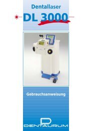
Laser welding - Examples for application in ... - DENTAURUM
Laser welding - Examples for application in ... - DENTAURUM
Laser welding - Examples for application in ... - DENTAURUM

Create successful ePaper yourself
Turn your PDF publications into a flip-book with our unique Google optimized e-Paper software.
laser <strong>weld<strong>in</strong>g</strong> examples prosthetics en<br />
<strong>Laser</strong> <strong>weld<strong>in</strong>g</strong><br />
<strong>Examples</strong> <strong>for</strong> <strong>application</strong> <strong>in</strong> prosthetics
<strong>Laser</strong> <strong>weld<strong>in</strong>g</strong> – Example <br />
CoCr model cast:<br />
Weld<strong>in</strong>g a small connector with filler material<br />
Preparation:<br />
The area to be welded is opened with a separat<strong>in</strong>g disc to produce a gap of 0.5 mm.<br />
Cast filler material of carbon-free CoCr alloy remanium ® CD (REF 102-350-00) is<br />
then fitted <strong>in</strong>to the gap. This filler material must be cast be<strong>for</strong>ehand <strong>in</strong> various<br />
wax-sheet thicknesses of 0.3 – 0.7 mm.<br />
The filler material is trimmed to size so that the dimension of the small connector<br />
appears circularly enlarged at approx. 0.5 mm. The parts to be welded are<br />
sand-blasted to a dull f<strong>in</strong>ish with Al 2 O 3 of gra<strong>in</strong> size 150 µm.<br />
The plate is tack-welded to one side of the connector with two laser weld spots.<br />
<strong>Laser</strong> sett<strong>in</strong>g: 275 V/5 ms.<br />
Us<strong>in</strong>g carbon-free CoCr laser wire (REF 528-200-00), weld one side of the<br />
remanium ® CD filler to the small connetor. Aim one third of the laser beam at<br />
the tip of the wire and two thirds at the gap to be filled.<br />
<strong>Laser</strong> sett<strong>in</strong>g: 290 V/9 ms.<br />
<strong>Laser</strong> <strong>weld<strong>in</strong>g</strong> wire is applied cont<strong>in</strong>uously to the jo<strong>in</strong>t area <strong>in</strong> the <strong>for</strong>m of a<br />
<strong>weld<strong>in</strong>g</strong> bead. The <strong>weld<strong>in</strong>g</strong> power must be selected <strong>in</strong> such a way that the laser<br />
beam penetrates to the centre of the object from either side.<br />
Fig. 1<br />
Stand 30.05.2007<br />
1/1
<strong>Laser</strong> <strong>weld<strong>in</strong>g</strong> – Example <br />
Fig. 2<br />
The same number of weld spots is applied alternately from above and below.<br />
Ensure that the weld area is well covered with argon. Turn the weld area so that<br />
it faces the argon nozzle. The weld spots should have a metallic lustre.<br />
Now beg<strong>in</strong> the actual jo<strong>in</strong><strong>in</strong>g process. The fille material is now welded to the second<br />
side of the small connector alternately from above and below us<strong>in</strong>g CoCr laser wire.<br />
<strong>Laser</strong> sett<strong>in</strong>g: 290 V/9 ms.<br />
Fig. 3<br />
1/2
<strong>Laser</strong> <strong>weld<strong>in</strong>g</strong> – Example <br />
F<strong>in</strong>ally, smoothen the surface with a soft polish<strong>in</strong>g sett<strong>in</strong>g. This is done either<br />
with a laser sett<strong>in</strong>g of 260 V and 9 ms by hold<strong>in</strong>g the object at a slight angle<br />
or with a laser unit with focus expansion (approx. 2/3 expanded beam, sett<strong>in</strong>g<br />
approx. 10) with a sett<strong>in</strong>g of 280 V and 10 ms.<br />
The jo<strong>in</strong>t is then processed <strong>in</strong> the same manner and polished. The model cast<br />
frame was made of the CoCr alloy remanium ® GM 800 (REF 102-200-00).<br />
Fig. 4<br />
1/3
<strong>Laser</strong> <strong>weld<strong>in</strong>g</strong> – Example <br />
CoCr model cast:<br />
Broken clasp<br />
The fracture area is sand-blasted to a dull f<strong>in</strong>ish on both sides with Al 2 O 3 of<br />
gra<strong>in</strong> size 150 µm. The broken clasp is adjusted to the correct position on the<br />
model and if necessary fixed to the plaster model with a drop of wax. The<br />
broken part is fixed to the upper arm of the brace with a eld spot.<br />
<strong>Laser</strong> sett<strong>in</strong>g: 265 V/5 ms. The fracture is then welded us<strong>in</strong>g carbon-free CoCr<br />
laser wire (REF 528-200-00). Aim one third of the laser beam at the tip of the<br />
wire and two thirds at the fracture.<br />
Ensure that the weld area is well covered with argon. The weld spots should<br />
have a metallic lustre.<br />
Weld the clasp alternately from the <strong>in</strong>side and outside.<br />
<strong>Laser</strong> wire is applied cont<strong>in</strong>uously to the fracture <strong>in</strong> <strong>for</strong>m of a <strong>weld<strong>in</strong>g</strong> bead.<br />
Fig. 1<br />
2/1
<strong>Laser</strong> <strong>weld<strong>in</strong>g</strong> – Example <br />
The surface of the weld is smoothened by the so-called smoothen<strong>in</strong>g process.<br />
The procedure is described <strong>in</strong> section 6.13 of the dental procedural <strong>in</strong>structions.<br />
The <strong>weld<strong>in</strong>g</strong> jo<strong>in</strong>t is then processed <strong>in</strong> the usual manner and polished. The model<br />
cast frame was made of the CoCr alloy remanium ® GM 800 (REF 102-200-00).<br />
Fig. 2<br />
2/2
<strong>Laser</strong> <strong>weld<strong>in</strong>g</strong> – Example <br />
CoCr model cast:<br />
Extension with bent retention.<br />
To extend a cast partial denture with a bent wire retention, the use of Co-based<br />
wires such as Dentaurum Redur ® is recommended. When us<strong>in</strong>g Redur ® wire<br />
1.75 x 0.9 mm (REF 528-158-00) a gap is first ground <strong>in</strong> the model-cast<br />
prosthesis us<strong>in</strong>g a separat<strong>in</strong>g disc.<br />
The Redur ® wire is then fitted <strong>in</strong>to this gap <strong>in</strong> such a way that no space is left.<br />
The areas to be welded are sand-blasted to a dull f<strong>in</strong>ish with Al 2 O 3 of gra<strong>in</strong> size<br />
150 µm. The CoCr wire is tack welded to the cast partial denture with one laserweld<br />
spot.<br />
<strong>Laser</strong> sett<strong>in</strong>g: 270 V/5 ms.<br />
Fig. 1<br />
3/1
<strong>Laser</strong> <strong>weld<strong>in</strong>g</strong> – Example <br />
Us<strong>in</strong>g carbon-free CoCr laser wire (REF 528-200-00), weld the two parts<br />
together. Aim one third of the laser beam at the tip of the wire and two thirds<br />
at the gap. Ensure that the weld area is well covered with argon.<br />
The weld spots should have a metallic lustre. The jo<strong>in</strong>t is welded completely on<br />
the top side and then <strong>in</strong> the same way on the opposite side.<br />
Weld<strong>in</strong>g material is fed constantly to the jo<strong>in</strong>t <strong>in</strong> the <strong>for</strong>m of a <strong>weld<strong>in</strong>g</strong> bead.<br />
Fig. 2<br />
3/2
<strong>Laser</strong> <strong>weld<strong>in</strong>g</strong> – Example <br />
The surface of the weld can be smoothened by the so-called smoothen<strong>in</strong>g<br />
process. The procedure is described <strong>in</strong> section 6.13 of the dental procedural<br />
<strong>in</strong>structions.<br />
The <strong>weld<strong>in</strong>g</strong> jo<strong>in</strong>t is then processed <strong>in</strong> the usual manner and polished.<br />
The frame <strong>for</strong> the l<strong>in</strong>gual bar was made of the CoCr alloy remanium ® GM 800<br />
(REF 102-200-00).<br />
Fig. 3<br />
3/3
<strong>Laser</strong> <strong>weld<strong>in</strong>g</strong> – Example <br />
Comb<strong>in</strong>ation weld <strong>for</strong> model of cast partial denture (CoCr)<br />
to secondary telescopes (Au-Pt).<br />
Preparation:<br />
A prefabricated retention <strong>in</strong> the <strong>for</strong>m of a conical peg (REF 111-901-00) is<br />
waxed to the secondary telescope.<br />
Fig. 1<br />
Fig. 2<br />
4/1
<strong>Laser</strong> <strong>weld<strong>in</strong>g</strong> – Example <br />
The cast partial denture is waxed up over this retenion and left open <strong>in</strong> the<br />
occlusal and tissue areas. To ensure the best possible fit, the jo<strong>in</strong><strong>in</strong>g gap must<br />
be kept as narrow as possible. The more accurately the work is done, the better<br />
the fit after <strong>weld<strong>in</strong>g</strong>. The parts to be welded are sand-blasted to a dull f<strong>in</strong>ish<br />
with Al 2 O 3 of gra<strong>in</strong> size 150 µm.<br />
Weld<strong>in</strong>g is carried out on the master model. The first two fix<strong>in</strong>g po<strong>in</strong>ts are<br />
located on the occlusal side <strong>in</strong> such a way that the weld on the opposite side<br />
is <strong>in</strong> the centre of the retention peg.<br />
<strong>Laser</strong> sett<strong>in</strong>g: 270 V/4 ms.<br />
Ensure that the weld area is well covered with argon. The weld spots should<br />
have a metallic lustre. The workpiece is then removed from the model and two<br />
fix<strong>in</strong>g po<strong>in</strong>ts are applied from the tissue side. The workpiece is then checked <strong>for</strong><br />
an accurate fit on the master model.<br />
Fig. 3<br />
4/2
<strong>Laser</strong> <strong>weld<strong>in</strong>g</strong> – Example <br />
Now weld the jo<strong>in</strong>t at high power alternately from the occlusal and tissue side.<br />
<strong>Laser</strong> sett<strong>in</strong>g: 280 V/5 ms.<br />
The number of weld po<strong>in</strong>ts oppos<strong>in</strong>g one another must be identical. If any<br />
warp<strong>in</strong>g should be noticed dur<strong>in</strong>g <strong>weld<strong>in</strong>g</strong>, it must be compensated by<br />
apply<strong>in</strong>g counter po<strong>in</strong>ts. It may there<strong>for</strong>e be necessary to apply a higher<br />
number of po<strong>in</strong>ts to one side of the weld <strong>in</strong> order to compensate <strong>for</strong> warp<strong>in</strong>g.<br />
Fig. 4<br />
In this manner, one jo<strong>in</strong><strong>in</strong>g element is fully welded be<strong>for</strong>e beg<strong>in</strong>n<strong>in</strong>g to weld the<br />
next secondary crown with the cast frame. This allows the exactness of the fit to<br />
be cont<strong>in</strong>uously monitored.<br />
The jo<strong>in</strong>t is closed <strong>in</strong>terdentally us<strong>in</strong>g a low <strong>weld<strong>in</strong>g</strong> power (270 V/4 ms).<br />
The secondary crowns were made from the alloy Orplid H by Hafner and the<br />
cast partial denture of the CoCr alloy remanium ® GM 700 (REF 102-100-00).<br />
4/3
<strong>Laser</strong> <strong>weld<strong>in</strong>g</strong> – Example <br />
<strong>Laser</strong> <strong>weld<strong>in</strong>g</strong> of galvano crowns. Connection with waxed<br />
up and cast pontics.<br />
Preparation:<br />
When wax<strong>in</strong>g up the pontic, it is recommended to <strong>for</strong>m a r<strong>in</strong>g brace or an E brace<br />
of the same thickness <strong>in</strong> the occlusal third around the galvano caps.<br />
The cast part is sand blasted with Al 2 O 3 of gra<strong>in</strong> size 80–100 µm at a pressure of<br />
3–4 bars. The galvano caps are given a dull appearance us<strong>in</strong>g a black marker pen.<br />
Important!<br />
Ensure that the frame fits onto the crowns without any tension and that the<br />
width of the gap between the galvano caps and the cast is as narrow as possible.<br />
Fig. 1<br />
If the preparatory work is accurate enough, it is not necessary to use fill<strong>in</strong>g<br />
material. If a wire is used, its diameter should be no greater than 0.4 mm.<br />
Diameter 0.35 mm (dull) is ideal. Material of the same type must be used.<br />
Basic laser sett<strong>in</strong>g: 270 V/7 ms, focus at 0 sett<strong>in</strong>g. When us<strong>in</strong>g a laser with<br />
adjustable focus, a wider weld can be achieved at a sett<strong>in</strong>g of 290 V/6 ms.<br />
Focus lever at sett<strong>in</strong>g 8–10 (<strong>for</strong> DL 2002 SFS) or 6 (<strong>for</strong> Desktop or Com4<strong>Laser</strong>).<br />
5/1
<strong>Laser</strong> <strong>weld<strong>in</strong>g</strong> – Example <br />
Procedure:<br />
1.) Position the frame free of stress on the crowns.<br />
2.) Fix<strong>in</strong>g is done on the master model.<br />
Sett<strong>in</strong>g 270 V/4 ms.<br />
Then remove and apply 4 counter po<strong>in</strong>ts at the same sett<strong>in</strong>g.<br />
3.) Application of weld:<br />
Sett<strong>in</strong>g: 270 V/7 ms.<br />
With more delicate structures, <strong>weld<strong>in</strong>g</strong> can be done safely by shift<strong>in</strong>g the<br />
crosshair by 2/3 to the r<strong>in</strong>g brace frame.<br />
The weld seam is applied with a 2/3 overlap on the upper and lower side of<br />
the r<strong>in</strong>g brace all the way around.<br />
A frequency of 2 Hz should not be exceeded with tack<strong>in</strong>g laser.<br />
<br />
<br />
Fig. 2<br />
Important!<br />
To avoid de<strong>for</strong>mation of the cervicel edge, a m<strong>in</strong>imum clearance of 2 mm should<br />
be created <strong>for</strong> the weld seam. (Do not wax up too closely to the preparation limit).<br />
F<strong>in</strong>ish the weld seam on one crown be<strong>for</strong>e <strong>weld<strong>in</strong>g</strong> the next.<br />
5/2
<strong>Laser</strong> <strong>weld<strong>in</strong>g</strong> – Example <br />
The galvano crowns were manufactured us<strong>in</strong>g the Hafner system.<br />
The pontic was cast of Orplid Keramik 2 (87,5% Au, 11% Pt), free of Pd, Cu and Ag.<br />
Color: yellow.<br />
Fig. 3<br />
5/3
<strong>Laser</strong> <strong>weld<strong>in</strong>g</strong> – Example <br />
Fig. 1<br />
<strong>Laser</strong> <strong>weld<strong>in</strong>g</strong> of ridge structures with implant based components<br />
Preparation:<br />
The structural components are screwed onto the implants. In this case, these are<br />
the cone shaped titanium elements with the compensat<strong>in</strong>g sleeve of the Tiolox ®<br />
implant system.<br />
The pre-fabricated structure elements are available from Dentaurum as<br />
rematitan ® bar and rematitan ® attachments <strong>in</strong> both micro and macro versions,<br />
complete with rematitan ® bar sleeve and retenion. The master model is prepared<br />
<strong>for</strong> the mount<strong>in</strong>g of the Paralas parallel align<strong>in</strong>g and fix<strong>in</strong>g device <strong>for</strong> the<br />
laser <strong>weld<strong>in</strong>g</strong> technique (REF 090-520-00).<br />
With the help of the <strong>in</strong>sert of the parallelometer, the model sleeve is embedded<br />
<strong>in</strong> plaster <strong>in</strong> a previously cut hole accord<strong>in</strong>g to the previously determ<strong>in</strong>ed path<br />
of <strong>in</strong>sertion. With the correct parallelometer <strong>in</strong>sert, the bar is placed between<br />
the compensat<strong>in</strong>g sleeves and cut to size with the conical titanium cutter<br />
maxi plus (REF 123-613-00).<br />
Fig. 2<br />
6/1
<strong>Laser</strong> <strong>weld<strong>in</strong>g</strong> – Example <br />
Fig. 3<br />
The rematitan ® bar must be fitted with great accuracy and without any gap,<br />
ensur<strong>in</strong>g perfect contact.<br />
Fix the screws <strong>for</strong> the mov<strong>in</strong>g parts of the Paralas <strong>in</strong> position.<br />
Beg<strong>in</strong> the jo<strong>in</strong>t between bar and structure with a tack weld. First apply a central<br />
vestibular weld spot to one end of the ridge.<br />
<strong>Laser</strong> sett<strong>in</strong>g: Voltage: 250 V<br />
Pulse duration: 3 ms<br />
Focus position: 0 gesetzt.<br />
Fig. 4<br />
Ensure that the weld area is well flooded with argon. The weld spots must have<br />
a metallic lustre.<br />
6/2
<strong>Laser</strong> <strong>weld<strong>in</strong>g</strong> – Example <br />
Then apply a counter spot from the l<strong>in</strong>gual side us<strong>in</strong>g the same power sett<strong>in</strong>g.<br />
The actual <strong>weld<strong>in</strong>g</strong> process is carried out from the vestibular and l<strong>in</strong>gual side<br />
with <strong>in</strong>creased power sett<strong>in</strong>gs etc.<br />
<strong>Laser</strong> sett<strong>in</strong>g: Voltage: 270 V<br />
Pulse duration: 4 ms<br />
Focus position: 0<br />
Important: each s<strong>in</strong>gle spot must be balanced by a s<strong>in</strong>gle spot on the oppos<strong>in</strong>g<br />
side made with the same sett<strong>in</strong>g parameters.<br />
Vestibular<br />
<br />
<br />
<br />
<br />
<br />
<br />
Oral<br />
1,2: Tack weld<br />
3,4,5 etc. Jo<strong>in</strong><strong>in</strong>g weld<br />
<br />
<br />
Fig. 4<br />
In this way, the rematitan ® bar is welded to the balanc<strong>in</strong>g sleeve all the way<br />
around, until a cont<strong>in</strong>uous bead of weld spots overlapp<strong>in</strong>g by 2/3 is achieved.<br />
At first, each bar is connected to only one implant post. Only afterwards is<br />
the other end of each bar welded. This ensures that the accuracy of the fit<br />
can be constantly monitored and the danger of warp<strong>in</strong>g <strong>in</strong> the structure<br />
as a whole, m<strong>in</strong>imized.<br />
6/3
<strong>Laser</strong> <strong>weld<strong>in</strong>g</strong> – Example <br />
Fig. 5<br />
After the <strong>weld<strong>in</strong>g</strong> process, the bar structure is f<strong>in</strong>ished and polished us<strong>in</strong>g the<br />
rematitan ® f<strong>in</strong>ish<strong>in</strong>g set (REF 135-500-00).<br />
Fig. 6<br />
The rematitan ® retentions are welded to the shortened rematitan ® sleeve with<br />
weld spots applied at the side.<br />
<strong>Laser</strong> sett<strong>in</strong>g: Voltage: 270 V<br />
Pulse duration: 1.5 ms<br />
Focus position: 0<br />
6/4
<strong>Laser</strong> <strong>weld<strong>in</strong>g</strong> – Example <br />
The pre-fabricated titanium structure components allow accurate and<br />
economical work<strong>in</strong>g with one type of material only.<br />
Fig. 7<br />
Complete rematitan ® ridge structure with rematitan ® rider <strong>in</strong> position.<br />
rematitan ® ridge components:<br />
REF<br />
210-010-00 rematitan ® bar h<strong>in</strong>ge macro complete 1 pack<br />
210-011-00 rematitan ® bar attachment macro complete 1 pack<br />
210-012-00 rematitan ® bar sleeve macro 1 piece<br />
210-020-00 rematitan ® bar h<strong>in</strong>ge micro complete 1 pack<br />
210-021-00 rematitan ® bar attachment micro complete 1 pack<br />
210-022-00 rematitan ® bar sleeve micro 1 piece<br />
6/5
Turnstraße 31 · 75228 Ispr<strong>in</strong>gen · Germany · Telephone +49 72 31 / 803-0 · Fax +49 72 31 / 803-295<br />
www.dentaurum.de · E-Mail: <strong>in</strong>fo@dentaurum.de<br />
989- 818-20 Pr<strong>in</strong>ted by Dentaurum Germany 05/07/A/R1