Operational Manual - DCU
Operational Manual - DCU
Operational Manual - DCU

Create successful ePaper yourself
Turn your PDF publications into a flip-book with our unique Google optimized e-Paper software.
@ TQ Education and Training Ltd 2000<br />
No part of this publication may be reproduced or transmitted in<br />
any form or by any means, electronic or mechanical, including<br />
photocopy, recording or any information storage and retrieval<br />
system without the express permission of TQ Education and<br />
Training Limited.<br />
All due care has been taken to ensure that the contents of this<br />
manual are accurate and up to date. However, if any errors are<br />
discovered please inform TQ so the problem may be rectified.<br />
A Packing Contents List is supplied with the equipment.<br />
Carefully check the contents of the package(s) against the list. If<br />
any items are missing or damaged, contact your local TQ agent<br />
orTQ immediately.<br />
PE/ajp/O200<br />
TQ Education and Training Ltt:l<br />
Products Divislolrl
~<br />
Section<br />
Contents<br />
1 INTRODUCTION 1<br />
2 ASSEMBLY<br />
~I<br />
How to Set up the Equipment<br />
3 TORSION TESTING<br />
5<br />
General Notes on Experimental Work<br />
~'<br />
~t<br />
Detailed Procedure<br />
3<br />
5<br />
4<br />
USE OF THE TORQUE METER AND PROCEDURE FOR<br />
CALIBRATION<br />
Procedure for Checking the Calibration<br />
Procedure for Full Calibration<br />
7<br />
7<br />
7<br />
5 EXPERIMENTATION<br />
Notes on Laboratory Sheets<br />
Object<br />
Apparatus<br />
Theory<br />
Experimental Procedure<br />
Results<br />
Suggested Increments of Strain<br />
Notes on the Content of the Laboratory Report<br />
Items to be Included<br />
Discussion of Results<br />
9<br />
9<br />
9<br />
9<br />
9<br />
9<br />
9<br />
9<br />
9<br />
10<br />
10<br />
TYPICAL EXPERIMENTAL RESULTS<br />
The Bauschinger Effect<br />
Upper and Lower Yield Strength of Mild Steel<br />
Relationship between Torque and Surface Stress<br />
Cast Iron<br />
6 11<br />
11<br />
11<br />
11<br />
12<br />
APPENDIX A<br />
APPENDIX B<br />
TORSION TEST SPECIMEN<br />
THE TORSIOMETER<br />
Introduction<br />
Construction<br />
Use and Operation of the Torsiometer<br />
Use<br />
Operation<br />
A-1<br />
A-2<br />
A-2<br />
A-2<br />
A-2<br />
A-2<br />
A-2
~<br />
m<br />
I,.<br />
r<br />
'1:-<br />
~-<br />
The 8Ml Torsion Testing Machine enables forward and<br />
reverse tests on standard 6 mm TQ torsion specimens,<br />
and other hexagon ended specimens requiring torques of<br />
up to 30 Nm. With additional chucks (optional extra) it<br />
can also be used for testing wire up to a length of 0.7 m.<br />
The apparatus is illustrated in Figure 2.<br />
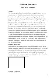
The loads are applied manually through a 60: 1<br />
reduction gearbox. The torque is reacted by a torsion bar<br />
(as shown in Figure 3), whose movement, relative to the<br />
displacement arm, is measured by a linear potentiometer<br />
connected to a TQ Digital Torque Meter. This mett:r is<br />
supplied as standard with the apparatus and is calibnued<br />
to give a readout of torque in Nm or lb.in (see Section 4<br />
on page 7).<br />
11
TQ Torsion Testing Machine<br />
Torque<br />
shaft<br />
DeftectkJn<br />
81m<br />
Lk18ar<br />
potentiometer<br />
Figure 3 End view of torque measurement system<br />
gearbox output shaft and can be used for measurement<br />
in the plastic range. A resettable counter is also fitted to<br />
the gearbox input shaft to give an overall record of input<br />
revolutions (note that one revolution represents 6°).<br />
Two pairs of hexagonal sockets are provided for<br />
holding standard TQ specimens. These sockets fit on the<br />
ends of the input and torque shafts as shown in Figure 2.<br />
The two pairs of hexagonal sockets provided are:<br />
. 3/16" Whitworth - for all specimens (the smaller<br />
sized sockets)<br />
. 12 mm AF - these can be used for cast iron<br />
specimens in order to accommodate any roughness<br />
on the cast ends<br />
In some cases it may be necessary to remove excessive<br />
bumps or flashing from specimens using a file.<br />
Accurate measurement of twist angles, and hence<br />
strain, can be obtained using the TQ Torsiometer which<br />
is an optional extra.<br />
The input rotation (the angle of twist of specimen) can<br />
be measured by three methods as in Figure 2. For<br />
accurate readings in the elastic range a protractor scale<br />
reading 0.10 is fitted to the input shaft of the gearbox. A<br />
second protractor scale reading 10 is fitted to the
SECTION 2 ASSEMBLY<br />
The apparatus is despatched fully assembled except for<br />
the following:<br />
(a) Adjustable feet (2 oft)<br />
(b) Levelling handwheel and tie rod assembly<br />
(c) Counter assembly<br />
sufficient room to insert a specimen between the<br />
sockets.<br />
To assemble, first lift each end of the apparatus in turn<br />
and screw an adjustable foot upwards into the<br />
appropriate hole in each of the end castings (see Figure I).<br />
Note that the plastic knob should point downwards and<br />
that there is only one adjustable foot at each end of the<br />
apparatus.<br />
Next fit the levelling handwheel between the torque<br />
arm and the lower bracket at the right of the apparatus.<br />
Secure the tie rod ends in position by inserting the<br />
screwed pins. Lock these in place by fitting the two split<br />
pins provided.<br />
Note: For safety reasons, the screwed pins must be<br />
screwed fully in and the split pins must be fitted to<br />
ensure that the joints do not work loose during<br />
operation.<br />
7:<br />
Fit the counter assembly as follows:<br />
1. Remove and retain the two cap head screws located<br />
on the top of the gearbox.<br />
2. Place the counter on the top of the gearbox with the<br />
cam follower lever resting on the carn of the<br />
handwheel.<br />
3. Secure the counter to the gearbox with the two<br />
screws removed in step (1).<br />
How to Set up the Equipment<br />
I. Level the rig on a suitable bench by adjusting the<br />
two adjustable feet.<br />
2. Connect the electrical lead from the output socket<br />
on the right of the apparatus to the input socket at<br />
the rear of the Digital Meter. Connect the meter to a<br />
mains supply and switch on.<br />
3. Select the required drive sockets and fit them to the<br />
input and torque shafts.<br />
4. Loosen the two locking knobs on the gearbox<br />
carriage and move the carriage along the bed such<br />
that, with the shaft fully to the left, there is just<br />
s.<br />
6.<br />
Set the deflection ann approximately level by<br />
adjusting the handwheel, then set the dial gau~;e to<br />
read zero by rotating the outer bezel. Tap the<br />
apparatus lightly and recheck the dial gauge.<br />
Select the desired range on the Digital Nleter<br />
(metric units or imperial). Set the reading to zero by<br />
adjusting the ZERO adjusting knob at the rear of<br />
the meter. Note that the meter is calibrated ~:fore<br />
leaving the factory, but if required the calibration<br />
can be checked using the procedure given in<br />
Section 4.<br />
If required, fit the Torsiometer to the specunen.<br />
Insert the specimen into one of the sockets, then<br />
rotate the handwheel until the second socket will<br />
slide freely onto the other end of the specimen.<br />
8. Take up any free movement by slowly rotatin!~ the<br />
handwheel clockwise until the Digital Meter<br />
reading just changes (i.e. a reading of 0.1 Nm or<br />
1.0 lb. in). Turning the handwheel clockwise ~~ives<br />
forward loading of the specimen, and anticlockwise<br />
gives reverse loading.<br />
9. Loosen the grubscrew on the scale, and positi,:>n it<br />
in line with the cursor. Set the reading to zero and<br />
lock the scale in position. Zero the counter by<br />
turning the knob at the far end of the counter.<br />
10. All zeros are now set and testing can commenc
SECTION 3 TORSION TESTING<br />
r<br />
General Notes on Experimental Work<br />
The tests possible with Torsion Testing Machine<br />
include the determination of the upper and lower yield<br />
strengths for nonnalised steel specimens, demonstration<br />
of the Bauschinger effect, and other effects relating to<br />
work hardening and heat-treatment. The detailed<br />
procedure outlined below should be followed in each<br />
case in order to maintain consistent readings of<br />
specimen twist using the scales provided. If a<br />
torsiometer is used, or if high accuracy is not required,<br />
there is no need to relevel the displacement arm before<br />
each reading (i.e. there is no need to maintain a zero<br />
reading on the dial gauge). This part of the procedure is<br />
only necessary in order to maintain the position of one<br />
end of the specimen stationary whilst registering the<br />
true angle of twist on the protractor scales. Omitting this<br />
step will not affect the accuracy of the torque readings.<br />
It should be noted here that the protractor scales only<br />
give an approximate measure of the twist of the<br />
specimen since readings include the twist of the drive<br />
shafts and specimen ends, and also any slight movement<br />
of the specimen ends in the drive sockets. These effects<br />
will be most significant in the elastic range where the<br />
load increases rapidly for only a small twist of the<br />
specimen. If the modulus of rigidity is to be determined,<br />
it is recommended that a torsiometer should be used.<br />
Reverse loads are applied by turning the handwheel<br />
anti-clockwise. Note that the Digital Meter reading will<br />
then be negative.<br />
IMPORTANT<br />
Always reduce the load to zero if it is required to<br />
remove a specimen before failure (for exam pIle,<br />
for heat treatment). DO NOT ATTEMPT TO<br />
REMOVE A SPECIMEN WHEN UNDER<br />
LOAD.<br />
Detailed<br />
Procedure<br />
1. For forward loading rotate the input handwheel<br />
clockwise until the input shaft has rotated, for<br />
example, through 0.5° as indicated by the dial.<br />
2. Return the reading on the dial gauge to zero by<br />
rotating the levelling handwheel.<br />
3. Record the torque displayed by the Digital Meter,<br />
noting the units and record the total angle of twist<br />
from zero.<br />
4. Repeathe procedure as required until the specimen<br />
has yielded or until all points of interred have l)een<br />
covered. Note that in the plastic range, angles of<br />
twist can be incremented to 6° or multiples of 6°.<br />
For ductile specimens, increments of up to 60° may<br />
be required, as some specimens require up to<br />
revolutions before failure occurs.<br />
r<br />
r<br />
r
~<br />
arm<br />
/ I.<br />
SECTION 4 USE OF THE TORQUE METER AND PROCEDURE FOR<br />
CALIBRATION<br />
r<br />
The apparatus is supplied complete with a Digital Meter<br />
for torque measurement and this is calibrated before<br />
leaving the factory. Four trimming controls are fitted to<br />
the rear of the meter as follows:<br />
a. ZERO adjustment knob - this is used for zeroing<br />
the meter (if necessary) prior to applying load.<br />
b. CAL screw - this can be used to adjust the<br />
calibration of the meter in the SI units mode.<br />
c. SI/lMP ADJUST screw - this adjusts the ratio<br />
between the SI and IMPERIAL units as selected by<br />
the SI/IMP switch at the front of the meter.<br />
d. DECIMAL POINTS - this can be used to determine<br />
the number of decimal points displayed.<br />
Controls (b) and (c) should not normally require<br />
adjustment, but if adjustment become necessary this<br />
should be done with care, as the controls are delicate.<br />
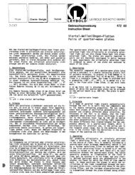
Procedure for Checking the Calibration<br />
Deflection<br />
arm "<br />
1"'3<br />
..,.<br />
Calibfation<br />
Dial<br />
gauge<br />
#_.<br />
Levelling<br />
handwheel<br />
Figure 4 Meter calibration using the loading arm<br />
1. For the calibration arm onto the square end of the<br />
torque shaft, then set the deflection arm<br />
approximately level by adjusting the handwheel<br />
(see Figure 4). Set the dial gauge to zero by rotating<br />
outer bezel. Tap the equipment lightly and recheck<br />
the dial gauge.<br />
2. Select SI units and set the Digital Meter to zero by<br />
adjusting the ZERO knob at the rear of the<br />
instrument.<br />
3. Add a load of 5 kg to the calibration arm and return<br />
the reading on the dial gauge to zero by rotating the<br />
handwheel. Check that the reading on the Digital<br />
Meter is 24.5 :to.5 Nm.<br />
4.<br />
5.<br />
Remove the load and check that the meter retools to<br />
zero.<br />
Note: If the error is greater than 0.5 Nm (i.e. 2%)<br />
the calibration should be adjusted using the CAL<br />
screw at the rear of the instrunlent to set the reading<br />
to 24.5 Nm when the load is 5 kg. For refer,ence<br />
purpose, note that the calibration ann is 500 mm<br />
long, hence 5 kg gives 5 x 9.81 x 0.5 = 24.53 Nm.<br />
If it is required to use imperial units (lbf.ft), re'peat<br />
the above procedure with the units switch sc:t to<br />
IMP and set the SI/IMP ADJ screw to give<br />
17.96 Ibf.ft.<br />
Procedure<br />
for Full Calibration<br />
For most purposes it can be assumed that the calibnltion<br />
is linear and setting at one value of load is adeqLlate.<br />
However, if required, the full calibration over the whole<br />
range can be checked as follows:<br />
I. Set an initial zero condition as in steps (I) and (2)<br />
in 'Procedure for Checking the Calibration'.<br />
2. Add weights to the weight hanger in the increments<br />
available (i.e. 500 g, I kg, 2 kg and a further :Z kg,<br />
plus weight hanger at 500 g) and record the meter<br />
reading at each value up to 6 kg. Return dial gauge<br />
to zero at each step, using the handwheel.<br />
3. Reduce the load in the same steps and again record<br />
the meter readings.<br />
4. Plot a graph of meter reading against applied torque<br />
(which equals 0.5 x load x 9.81 Nm). Draw a mean<br />
line through the points and calculate the slOlle of<br />
the line (ideally unity). If there is a significant t:rror,<br />
apply a load of 5 kg, note the reading and divide<br />
this by the average slope, then reset the meter to<br />
this new value.<br />
S. The above procedure can then be repeate,:i, if<br />
desired, to check that the resulting calibration is<br />
correct.<br />
It may be noted that the graph plotted in step (4) will<br />
also show the linearity of the torque measuring system<br />
and any hysteresis which is present due to stiction in the<br />
torque shaft bearings. It will be found that both these<br />
sources of error are mall, but students should be aware<br />
of their existence and should comment on them in their<br />
laboratory reports.
SECTION 5 EXPERIMENTATION<br />
r<br />
r<br />
The fonn of Laboratory Sheets and Reports quite<br />
obviously will depend very much on the individual<br />
lecturer and the type of experiment being carried out;<br />
however for the more elementary work the following<br />
example serve as a guide for the student operator.<br />
Notes on Laboratory Sheets<br />
Using a Torsion Test to Destruction as an example, the<br />
following is a suggested layout for a laboratory sheet.<br />
Object<br />
To carry out a torsion test to destruction in order to<br />
determine for a specimen:<br />
(a) The modulus of rigidity<br />
(b) The shear stress at the limit of proportionality<br />
(c) The general characteristics of the torque, angle of<br />
twist relationship.<br />
Apparatus<br />
Torsion Testing Machine and Torsiometer, steel rule<br />
and micrometer.<br />
Theory<br />
From the general torsion theory for a circular specimen:<br />
T Ge 't<br />
- = =-<br />
J<br />
where:<br />
I<br />
r<br />
T= Applied torque Nm or lbfin<br />
J = Polar second moment of area mm or in<br />
G = Modulus of rigidity N/mm2 of Ibf/in2<br />
e = Angle of twist (over length) radians<br />
I = Gauge length mm or in<br />
t = Shear stress at radius r N/mm2 or 1 bf/in2<br />
r = Radius mm or in<br />
Experimental Procedure<br />
I. Measure the overall length and diameter of the test<br />
section of the specimen.<br />
2. Draw a line down the length of the test section of<br />
the specimen with a pencil; this serves as a visual<br />
aid to the degree of twist being put on the specimen<br />
during loading.<br />
3. Mount the specimen finnly in the Torsion Testing<br />
Machine. For each increment of strain record the<br />
following:<br />
(a) Angle of twist of the specimen in degrees<br />
(b) Applied torque<br />
(c) Angle of twist over the 50 mm gauge length in<br />
radians, as recorded by the dial gauge indicator<br />
(d) When the elastic limit has been passed<br />
continue to test to destruction with ever<br />
increasing increments of strain, recording for<br />
each strain increment:<br />
]. Angle of twist in degrees<br />
2. Applied torque<br />
Note: In some tests it may be found unnecessary to use<br />
the torsiometer after the elastic limit has been reached.<br />
If this is the case, the torsiometer can be removed from<br />
the specimen and readings of twist can be taken din:ctly<br />
from the machine scales. To remove the Torsiom'~ter,<br />
unclamp the two cap screws securing it to the specimen<br />
and slip each end clamp off the specimen. The end<br />
clamps have been slotted for this purpose. It is not<br />
possible to remove the centre cylindrical spacer of the<br />
Torsiometer as this would involve disturbing the end<br />
fixing of the specimen, i.e. releasing it from the chuck.<br />
This should be done under any circumstances during<br />
test.<br />
Results<br />
Initial diameter of specinen<br />
Final diameter of soedmen<br />
Gauge length ~ specinen<br />
Initial overall length of spec"men<br />
Final overall length of specimen<br />
Tabulate the results under pressure headings for the<br />
elastic and non-elastic regions.<br />
Suggested Increments of Strain<br />
To ensure that an adequate number of values are<br />
obtained from the test, particularly during the elastic<br />
region of strain, the following is recommended:<br />
Notes on the Content of the Laboratory<br />
Report<br />
As in the case of the Laboratory Sheet the content of the<br />
report will depend largely on the type of test carrie
TQ Torsion Testing Machine<br />
Items to be Included<br />
Include in the report a dimensioned drawing of the<br />
specimen. Using the tabulated results plot a graph of<br />
applied torque, T, against angle of twist a as a base for<br />
the elastic region. Use the slope of this graph to<br />
determine the value of the modules of rigidity. Also<br />
from this graph determine the torque, and then calculate<br />
the shear stress at the limit of proportionality. Plot a<br />
graph of applied torque against angle of twist of the<br />
specimen as a base, for the complete test to destruction.<br />
Discussion of Results<br />
1. State, and comment upon, the values obtained from<br />
the test.<br />
2. Comment upon the overall result obtained from the<br />
test.<br />
3. Comment upon the apparatus and procedures.<br />
4. Discuss the errors involved in determining the<br />
modulus of rigidity using the angle of twist from<br />
the machine dial, and compare the results obtained<br />
with the value found by using the Torsiometer.
SECTION 6 TYPICAL EXPERIMENTAL RESULTS<br />
The Bauschinger Effect<br />
When a metal bar is subjected to torsional overstrain<br />
and the load then removed, the load-free bar is full of<br />
residual stresses. These stresses are of two kinds:<br />
I. Body stresses which affect a relatively large<br />
volume of metal (i.e. macro stresses), and<br />
2. Textural stresses which are really the residual<br />
stresses in between and within the crystals of the<br />
metal caused by deformation of each crystal (i.e.<br />
they are in the actual texture of the metal).<br />
Fortunately body stresses (which are beneficial) are<br />
more stable than textural stresses (which are harmful),<br />
the latter being removed by a low temperature heat<br />
treatment of 200°C.<br />
greater dIan dIe torque at G. This shift of dIe strength<br />
range in dIe direction of dIe plastic defonnation is<br />
sometimes called the 'Bauschinger Effect'.<br />
Upper and Lower Yield Strength Mild StEtel<br />
Normalised mild steel has the peculiar propert)' of<br />
having an upper and lower yield strength. That is, the<br />
initiation of yield occurs at a greater stress than the<br />
propagation of yield along the bar.<br />
This is demonstrated in Figure 6 where, after the ulitial<br />
yielding of the specimen, point A, the load immediately<br />
fallen to a lower value, point B. The strain reduces until<br />
the specimen is again in the elastic range, point C, but<br />
when reloaded it yields at the lower yield strength, lJOint<br />
D, showing that with mild steel the yield propagates at<br />
the lower yield strength stress value.<br />
Figure 5 Reverse torsion tests Relationship between Torque and Surlace<br />
Stress<br />
Reverse torsion tests are possible on the Torsion Testing<br />
Machine, allowing residual stress phenomena to be<br />
readily demonstrated, as shown in Figure 5. In the initial<br />
load cycle the specimen yields at A, is plastically<br />
defoTDled to B, then unloaded and plastically deformed<br />
in the reverse direction to point C. It is then loaded in<br />
the positive direction to point 0, unloaded and given a<br />
low temperature heat treatment, and then reloaded. It<br />
now yields at F rather than O. Thus the harmful effects<br />
of the textural stresses, which were removed by the heat<br />
treatment, were equal to OF. The vertical distance of<br />
point F represents the beneficial effect of the body<br />
stresses.<br />
If the material is now strained to point E and then<br />
strained in the reverse direction to point K (i.e. sight<br />
negative plastic strain). On reloading it arrives back at<br />
the strain represented by point E at a lower torque value<br />
G. Thus, during the strain cycle the strength range has<br />
moved in the negative direction that is the torque at F is<br />
During both the elastic and plastic range of torsional<br />
strain, the relationship between applied torque, 7: and<br />
the maximum shear stress, which occurs at the surface<br />
'tmax, is proportional to 1/ d', the actual relationship<br />
depending upon the stress strain characteristics of the<br />
material being tested. In the elastic range the precise<br />
relationship is:<br />
16T<br />
't= -r<br />
Jtd<br />
Normally this relationship for stress is used throu~~out<br />
the test, but in the plastic region. t is a nominal !;tress<br />
and not the real stress. The real stress is less thw:l the<br />
nominal stress.
APPENDIX A<br />
TORSION TEST SPECIMEN<br />
~ A standard range of metric specimens can be supplied For specimens of gauge 6", see catalogue order no.<br />
by TQ. Each specimen is stamped with a code reference TRIO6O to TRIO85.<br />
and has dimensions as shown in Figure 9.<br />
.I<br />
Figure A 1 Standard torsion specimen<br />
r
APPENDIX B THE TORSIOMETER<br />
Introduction<br />
The TQ Torsiometer has been speciany designed to fit<br />
onto the standard test specimens listed above. The<br />
Torsiometer can accommodate the fun range of strain<br />
by continual adjustment of its dial indicator and can<br />
thus be used to accurately measure strains in both the<br />
elastic and plastic regions.<br />
Construction<br />
A sectional arrangement of the Torsiometer is shown in<br />
Figure 10. It consists of two end clamps, which are<br />
located axially by the centre cylindrical spacer. Each<br />
end clamp contains a 90° cone point socket headed cap<br />
screw, used to clamp the Torsiometer onto the<br />
specimen. A gauge length of 50 millimetres is<br />
maintained between the two clamping screws by the<br />
intermediate spacer.<br />
The end clamps are slotted to facilitate easy<br />
insertion and removal of the specimen. Each end cap<br />
contains two hardened steel rollers to locate the<br />
Torsiometer centrally onto the specimen when clamped<br />
in position. The two component parts of the end clamp<br />
are held rigidly together by the knurled nut. The lefthand<br />
end clamp carries a dial gauge reading to an<br />
accuracy of 0.00 I of an inch. The plunger of the dial<br />
gauge is positioned exactly one inch from the centre of<br />
the specimen and bears on the flat portion of a rod,<br />
which is integral with right-hand clamp. This<br />
positioning of the dial gauge relative to the other over<br />
its gauge length will be represented on the dial gauge in<br />
0.00 I of an inch.<br />
Note that an angular displacement on the dial gauge<br />
represented by 0.001 of an inch is equivalent to an<br />
angular displacement of 0.001 radian. This is because<br />
the dial gauge plunger is exactly 1 inch from the<br />
specimen centreline, acting on a circumference of 27t<br />
radians in a circle the angular displacement shown on<br />
the dial gauge in inches is therefore equivalent to<br />
angular displacement in radians.<br />
Use and Operation<br />
of the Torsiometer<br />
Use<br />
The Torsiometer should be used where more accurate<br />
measurement of strain over a precise gauge length is<br />
desired. Strain can be measured accurately in both the<br />
elastic and plastic regions, thus allowing the Modulus of<br />
Rigidity to the determined in the elastic region and also<br />
providing very accurate means of measuring the work<br />
hardening properties of the specimen. To continue<br />
reading on the dial indicator over these regions it will be<br />
found necessary to adjust the assembly as described at<br />
the end of this section.<br />
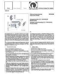
Operation<br />
Place the Torsiometer on the specimen. This is done in<br />
three stages, referring to Figure A2.<br />
I. Push one end of the specimen firmly into the socket<br />
mounted on the tailstock of the Torsion Machine.<br />
Separate the Torsiometer into its three main<br />
components - the two end clamps and the<br />
cylindrical centre spacer.<br />
Rod<br />
I~"<br />
,-<br />
End<br />
,clamp<br />
-1$1-<br />
End<br />
I<br />
cap'" r , -'1~ 1t"-T- ,/ End<br />
\<br />
.-" cap<br />
.~<br />
/<br />
Cap<br />
screw \<br />
End<br />
Knurled<br />
clamp Centre nut<br />
Figure A2 Layout of the torsiometer<br />
spacer<br />
'Cap<br />
screw<br />
Page A-2
Ta Torsion Testing Machine<br />
[<br />
r:<br />
2.<br />
3.<br />
Slide the cylindrical spacer over the specimen and<br />
onto the spigot on the right-hand end clamp.<br />
Place the remaining end clamp onto the specimen<br />
taking care to locate the spigot on this end clamp as<br />
far as possible into the open end of the spacer. Turn<br />
the end lamp until the dial gauge plunger contacts<br />
the flat on the end of the rod. The dial gauge should<br />
be in such a position that the dial is clearly visible.<br />
Hold the three components together and ftTDlly<br />
tighten the cap screw in the left-hand end clamp.<br />
The spacer should just be free to rotate without any<br />
end play. The whole assembly firmly fixes to the<br />
test specimen and the tailstock can be slid along the<br />
bed until the free hexagon end of the specimen is<br />
inside the headstock socket. Lock the straining head<br />
in position.<br />
The Torsiometer is now ready for use. Should the full<br />
scale deflection of the dial gauge be insufficient at this<br />
first clamp position of the rod it may be adjusted to<br />
register further straining of the specimen by just<br />
slackening the knurled nut and resetting the position of<br />
the rod. In this way the position of the TorsioI11leter<br />
clamping on the specimen is in no way disturbed, and<br />
continual adjustment throughout the whole loading<br />
range is obtained.<br />
r<br />
r<br />
r