Wheelock - Cooper Industries
Wheelock - Cooper Industries
Wheelock - Cooper Industries

Create successful ePaper yourself
Turn your PDF publications into a flip-book with our unique Google optimized e-Paper software.
Thank you for using our products.<br />
273 Branchport Avenue<br />
Long Branch, N.J. 07740<br />
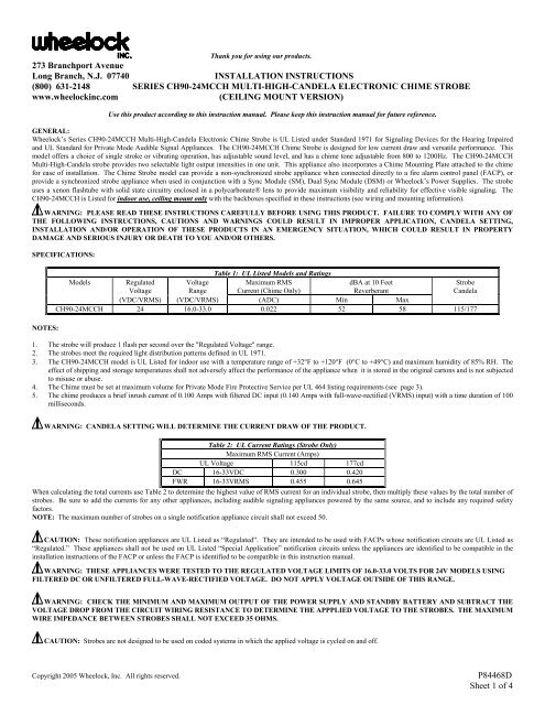
INSTALLATION INSTRUCTIONS<br />
(800) 631-2148 SERIES CH90-24MCCH MULTI-HIGH-CANDELA ELECTRONIC CHIME STROBE<br />
www.wheelockinc.com<br />
(CEILING MOUNT VERSION)<br />
Use this product according to this instruction manual. Please keep this instruction manual for future reference.<br />
GENERAL:<br />
<strong>Wheelock</strong>’s Series CH90-24MCCH Multi-High-Candela Electronic Chime Strobe is UL Listed under Standard 1971 for Signaling Devices for the Hearing Impaired<br />
and UL Standard for Private Mode Audible Signal Appliances. The CH90-24MCCH Chime Strobe is designed for low current draw and versatile performance. This<br />
model offers a choice of single stroke or vibrating operation, has adjustable sound level, and has a chime tone adjustable from 800 to 1200Hz. The CH90-24MCCH<br />
Multi-High-Candela strobe provides two selectable light output intensities in one unit. This appliance also incorporates a Chime Mounting Plate attached to the chime<br />
for ease of installation. The Chime Strobe model can provide a non-synchronized strobe appliance when connected directly to a fire alarm control panel (FACP), or<br />
provide a synchronized strobe appliance when used in conjunction with a Sync Module (SM), Dual Sync Module (DSM) or <strong>Wheelock</strong>’s Power Supplies. The strobe<br />
uses a xenon flashtube with solid state circuitry enclosed in a polycarbonate® lens to provide maximum visibility and reliability for effective visible signaling. The<br />
CH90-24MCCH is Listed for indoor use, ceiling mount only with the backboxes specified in these instructions (see wiring and mounting information).<br />
WARNING: PLEASE READ THESE INSTRUCTIONS CAREFULLY BEFORE USING THIS PRODUCT. FAILURE TO COMPLY WITH ANY OF<br />
THE FOLLOWING INSTRUCTIONS, CAUTIONS AND WARNINGS COULD RESULT IN IMPROPER APPLICATION, CANDELA SETTING,<br />
INSTALLATION AND/OR OPERATION OF THESE PRODUCTS IN AN EMERGENCY SITUATION, WHICH COULD RESULT IN PROPERTY<br />
DAMAGE AND SERIOUS INJURY OR DEATH TO YOU AND/OR OTHERS.<br />
SPECIFICATIONS:<br />
NOTES:<br />
Table 1: UL Listed Models and Ratings<br />
Models Regulated Voltage Maximum RMS dBA at 10 Feet Strobe<br />
Voltage Range Current (Chime Only) Reverberant Candela<br />
(VDC/VRMS) (VDC/VRMS) (ADC) Min Max<br />
CH90-24MCCH 24 16.0-33.0 0.022 52 58 115/177<br />
1. The strobe will produce 1 flash per second over the "Regulated Voltage" range.<br />
2. The strobes meet the required light distribution patterns defined in UL 1971.<br />
3. The CH90-24MCCH model is UL Listed for indoor use with a temperature range of +32°F to +120°F (0°C to +49°C) and maximum humidity of 85% RH. The<br />
effect of shipping and storage temperatures shall not adversely affect the performance of the appliance when it is stored in the original cartons and is not subjected<br />
to misuse or abuse.<br />
4. The Chime must be set at maximum volume for Private Mode Fire Protective Service per UL 464 listing requirements (see page 3).<br />
5. The chime produces a brief inrush current of 0.100 Amps with filtered DC input (0.140 Amps with full-wave-rectified (VRMS) input) with a time duration of 100<br />
milliseconds.<br />
WARNING: CANDELA SETTING WILL DETERMINE THE CURRENT DRAW OF THE PRODUCT.<br />
Table 2: UL Current Ratings (Strobe Only)<br />
Maximum RMS Current (Amps)<br />
UL Voltage 115cd 177cd<br />
DC 16-33VDC 0.300 0.420<br />
FWR 16-33VRMS 0.455 0.645<br />
When calculating the total currents use Table 2 to determine the highest value of RMS current for an individual strobe, then multiply these values by the total number of<br />
strobes. Be sure to add the currents for any other appliances, including audible signaling appliances powered by the same source, and to include any required safety<br />
factors.<br />
NOTE: The maximum number of strobes on a single notification appliance circuit shall not exceed 50.<br />
CAUTION: These notification appliances are UL Listed as “Regulated”. They are intended to be used with FACPs whose notification circuits are UL Listed as<br />
“Regulated.” These appliances shall not be used on UL Listed “Special Application” notification circuits unless the appliances are identified to be compatible in the<br />
installation instructions of the FACP or unless the FACP is identified to be compatible in this instruction manual.<br />
WARNING: THESE APPLIANCES WERE TESTED TO THE REGULATED VOLTAGE LIMITS OF 16.0-33.0 VOLTS FOR 24V MODELS USING<br />
FILTERED DC OR UNFILTERED FULL-WAVE-RECTIFIED VOLTAGE. DO NOT APPLY VOLTAGE OUTSIDE OF THIS RANGE.<br />
WARNING: CHECK THE MINIMUM AND MAXIMUM OUTPUT OF THE POWER SUPPLY AND STANDBY BATTERY AND SUBTRACT THE<br />
VOLTAGE DROP FROM THE CIRCUIT WIRING RESISTANCE TO DETERMINE THE APPPLIED VOLTAGE TO THE STROBES. THE MAXIMUM<br />
WIRE IMPEDANCE BETWEEN STROBES SHALL NOT EXCEED 35 OHMS.<br />
CAUTION: Strobes are not designed to be used on coded systems in which the applied voltage is cycled on and off.<br />
Copyright 2005 <strong>Wheelock</strong>, Inc. All rights reserved.<br />
P84468D<br />
Sheet 1 of 4
WARNING: MAKE SURE THAT THE TOTAL RMS CURRENT REQUIRED BY ALL APPLIANCES THAT ARE CONNECTED TO THE<br />
SYSTEM’S PRIMARY AND SECONDARY POWER SOURCES, NOTIFICATION APPLICIANCE CIRCUITS, SM, DSM SYNC MODULES, OR<br />
WHEELOCK POWER SUPPLIES DOES NOT EXCEED THE POWER SOURCES’ RATED CAPACITY OR THE CURRENT RATINGS OF ANY FUSES<br />
ON THE CIRCUITS TO WHICH THESE APPLIANCES ARE WIRED. OVERLOADING POWER SOURCES OR EXCEEDING FUSE RATINGS<br />
COULD RESULT IN LOSS OF POWER AND FAILURE TO ALERT OCCUPANTS DURING AN EMERGENCY, WHICH COULD RESULT IN<br />
PROPERTY DAMAGE AND SERIOUS INJURY OR DEATH TO YOU AND/OR OTHERS.<br />
WIRING AND MOUNTING INFORMATION:<br />
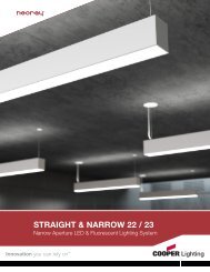
CAUTION: The following figures (A,B) show the maximum number of field wires (conductors) that can enter the backbox used with each mounting option. If<br />
these limits are exceeded, there may be insufficient space in the backbox to accommodate the field wires and stresses from the wires could damage the product.<br />
CAUTION: Check that the installed product will have sufficient clearance and wiring room prior to installing backboxes and conduit, especially if sheathed<br />
multiconductor cable or 3/4" conduit fittings are used.<br />
Although the limits shown for each mounting option comply with the National Electrical Code (NEC), <strong>Wheelock</strong> recommends use of the largest backbox option shown<br />
and the use of approved stranded field wires, whenever possible, to provide additional wiring room for easy installation and minimum stress on the product from wiring.<br />
A<br />
4" SQ. X 1-1/2"<br />
EXTENSION RING *<br />
#8-32<br />
SCREWS<br />
FLUSH MOUNTING<br />
(STROBE SPEAKER)<br />
4" SQ. X 2-1/8"<br />
BACKBOX<br />
B<br />
SURFACE MOUNTING<br />
(STROBE SPEAKER)<br />
SURFACE<br />
BACKBOX<br />
(SBB)<br />
#8-32<br />
SCREWS<br />
SQUARE OR<br />
ROUND GRILLE<br />
#6-19<br />
SCREWS<br />
SPEAKER<br />
MOUNTING<br />
PLATE<br />
SQUARE OR<br />
ROUND GRILLE<br />
#6-19<br />
SCREWS<br />
SPEAKER<br />
MOUNTING<br />
PLATE<br />
MAXIMUM NUMBER OF CONDUCTORS<br />
AWG #18 AWG #16<br />
8 8<br />
AWG #14<br />
AWG #12<br />
8 8<br />
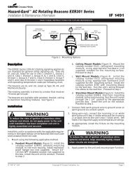
Figure 1:<br />
Chime Appliance and Strobe Appliance operate independently. Recommended for<br />
coded systems where the chime is set on single stroke (SS) mode and is cycled on<br />
and off while the strobe flashes continuously.<br />
NOTE: BACKBOX IS COMPATIBLE WITH WIREMOLD AND CONDUIT,<br />
MOUNTING HOLES ARE FOR SINGLE-GANG, DOUBLE-GANG,<br />
4" SQ. 3-1/2" & 4" OCTAGON OR ROUND BACKBOXES.<br />
MAXIMUM NUMBER OF CONDUCTORS<br />
AWG #18 AWG #16<br />
8 8<br />
AWG #14<br />
AWG #12<br />
8 8<br />
Figure 2:<br />
Chime Appliance and Strobe Appliance operate in unison. Red and black wires are<br />
supplied. The chime must be set for vibrating mode (VIB). (Use of Sync Module is<br />
not recommended in this wiring option)<br />
FROM PRECEDING<br />
CHIME OR FIRE<br />
ALARM CONTROL<br />
PANEL (FACP)<br />
FROM PRECEDING<br />
STROBE, FACP<br />
SYNC MODULE OR<br />
POWER BOOSTER *<br />
TO NEXT<br />
CHIME OR<br />
END OF LINE RESISTOR<br />
(EOLR)<br />
TO NEXT<br />
STROBE OR EOLR<br />
FROM<br />
PRECEDING<br />
APPLIANCE OR<br />
FIRE ALARM<br />
CONTROL PANEL<br />
(FACP)<br />
RED<br />
BLACK<br />
STROBE CHIME<br />
TO NEXT<br />
APPLIANCE OR<br />
END OF LINE<br />
RESISTOR<br />
(EOLR)<br />
STROBE CHIME<br />
* Refer to instruction sheets for SM (P83123), DSM (P83177) or <strong>Wheelock</strong> power supplies for additional information.<br />
Figure 3:<br />
• The Chime Strobe model has in-out wiring terminals that accept two #12 to #18 American Wire<br />
Gauge (AWG) wires at each screw terminal. Strip leads 3/8 inches and connect to screw terminals.<br />
• Break all in-out wire runs on supervised circuits to assure integrity of circuit supervision as shown in<br />
Figure 3. The polarity shown in the wiring diagrams is for operation of the appliances. The polarity<br />
is reversed by the FACP during supervision.<br />
GROUNDING: Install the appliance to a grounded backbox (Per NFPA 70, the National Electrical Code) using the lockwashers provided in hardware bag under the<br />
head of each mounting screw for the appliance.<br />
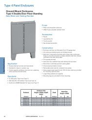
Figure 4: PC Board Layout<br />
P84468 D<br />
Sheet 2 of 4
VIB<br />
LO<br />
TONE<br />
SS<br />
LO<br />
HI<br />
VOLUME<br />
CHIME<br />
STROBE<br />
1. The chime is factory set in single stroke (SS) mode. It can be changed<br />
to vibrating (VIB) mode before wiring the appliance with the<br />
provided jumper. Refer to PC Board layout shown in Figure 4. (SS =<br />
single stroke, VIB = vibrating)<br />
SINGLE STROKE OPERATION: The minimum input pulse duration<br />
must be at least 160 milliseconds "on" time and 160 milliseconds<br />
"off" time. The chime will only operate once each time it is pulsed.<br />
This mode is recommended for coded systems.<br />
VIBRATING OPERATION: Continuous input voltage must be<br />
applied to the chime to activate the chime at one second intervals.<br />
2. The volume and tone controls have been adjusted at the factory to<br />
insure maximum dBA output. However, once the mode is selected,<br />
the installer may want to fine tune the appliance to better suit the<br />
application.<br />
HI<br />
Figure 5:<br />
177<br />
115<br />
INSERT<br />
SCREWDRIVER<br />
CANDELA<br />
POINTER<br />
NOTE: The CH90-24MCCH comes pre-set at 177cd.<br />
WARNING: THE CANDELA SELECT SWITCH MUST BE FIELD SET TO THE REQUIRED CANDELA INTENSITY BEFORE INSTALLATION.<br />
WHEN CHANGING THE SETTING OF THE CANDELA SELECT SWITCH, MAKE CERTAIN THAT IT “CLICKS” IN PLACE. AFTER CHANGING<br />
THE CANDELA SETTING, THE APPLIANCE MUST BE RETESTED TO VERIFY PROPER OPERATION. IMPROPER SETTING OF THE CANDELA<br />
SELECT SWITCH, MAY RESULT IN OPERATION AT THE WRONG CANDELA, WHICH COULD RESULT IN PROPERTY DAMAGE AND<br />
SERIOUS INJURY OR DEATH TO YOU AND/OR OTHERS.<br />
MOUNTING PROCEDURES:<br />
1. This model can be flush mounted to a 4” square by 2-1/8” deep backbox with a 4” square 1-1/2” extension ring (Figure A). surface mounted to a Surface Backbox<br />
(Figure B). Mounting hardware for each mounting option is supplied.<br />
2. Conduit entrances to the backbox should be selected to provide sufficient wiring clearance for the installed product. Do not pass additional wires (used for other<br />
than the signaling appliance) through the backbox. Such additional wires could result in insufficient wiring space for the signaling appliance.<br />
3. When terminating field wires, do not use more lead length than required. Excess lead length could result in insufficient wiring space for the signaling appliance.<br />
4. Use care and proper techniques to position the field wires in the backbox so that they use minimum space and produce minimum stress on the product. This is<br />
especially important for stiff, heavy gauge wires and wires with thick insulation or sheathing.<br />
5. CH90-24MCCH model has an integrated mounting plate which must be oriented correctly when it is mounted to the backbox. Turn the mounting plate so that the<br />
arrow above the words “Horizontal Strobe” or “Top” points to the top side of the mounting plate<br />
6. To move selector switch, insert screwdriver into slot shown on the bottom side of the strobe. See Figure 5.<br />
7. Mount the chime mounting plate to the backbox with the cone protector on. After the chime mounting plate is attached to the backbox, remove the cone protector<br />
before installing the grille. Next, attach the grille to the chime mounting plate and attach with (2) screws.<br />
WARNING: THE CHIME STROBE APPLIANCE IS A "FIRE ALARM DEVICE - DO NOT PAINT."<br />
WARNING: WHEN INSTALLING STROBES IN AN OPEN OFFICE OR OTHER AREAS CONTAINING PARTITIONS OR OTHER VIEWING<br />
OBSTRUCTIONS, SPECIAL ATTENTION SHOULD BE GIVEN TO THE LOCATION OF THE STROBES SO THAT THEIR OPERATING EFFECT<br />
CAN BE SEEN BY ALL INTENDED VIEWERS, WITH THE INTENSITY, NUMBER, AND TYPE OF STROBES BEING SUFFICIENT TO MAKE SURE<br />
THAT THE INTENDED VIEWER IS ALERTED BY PROPER ILLUMINATION, REGARDLESS OF THE VIEWER'S ORIENTATION. FAILURE TO<br />
DO SO COULD RESULT IN PROPERTY DAMAGE AND SERIOUS INJURY OR DEATH TO YOU AND/OR OTHERS.<br />
WARNING: A SMALL POSSIBILITY EXISTS THAT THE USE OF MULTIPLE STROBES WITHIN A PERSON'S FIELD OF VIEW, UNDER<br />
CERTAIN CIRCUMSTANCES, MIGHT INDUCE A PHOTO-SENSITIVE RESPONSE IN PERSONS WITH EPILEPSY. STROBE REFLECTIONS IN A<br />
GLASS OR MIRRORED SURFACE MIGHT ALSO INDUCE SUCH A RESPONSE. TO MINIMIZE THIS POSSIBLE HAZARD, WHEELOCK<br />
STRONGLY RECOMMENDS THAT THE STROBES INSTALLED SHOULD NOT PRESENT A COMPOSITE FLASH RATE IN THE FIELD OF VIEW<br />
WHICH EXCEEDS FIVE (5) Hz AT THE OPERATING VOLTAGE OF THE STROBES. WHEELOCK ALSO STRONGLY RECOMMENDS THAT THE<br />
INTENSITY AND COMPOSITE FLASH RATE OF INSTALLED STROBES COMPLY WITH LEVELS ESTABLISHED BY APPLICABLE LAWS,<br />
STANDARDS, REGULATIONS, CODES AND GUIDELINES.<br />
P84468 D<br />
Sheet 3 of 4
The 177 cd Setting is Listed for use in sleeping or non-sleeping areas when installed in accordance with appropriate NFPA Standards and the Authority Having<br />
Jurisdiction.<br />
NOTE: NFPA 72/ANSI 117.1 conform to ADAAG Equivalent Facilitation Guidelines in using fewer, higher intensity strobes within the same protected area.<br />
This control unit does not generate a temporal pattern signal. If the distinctive three-pulse temporal pattern fire alarm evacuation signal (or total evacuation) in<br />
accordance with NFPA 72 is required, the control unit must be used with appliances that can generate the temporal pattern signal. Refer to Manufacturer’s instruction<br />
manual for details.<br />
CAUTION: Check the installation instructions of the manufacturers of other equipment used in the system for any guidelines or restrictions on wiring and/or<br />
locating Notification Appliance Circuits (NAC) and notification appliances. Some system communication circuits and/or audio circuits, for example, may require<br />
special precautions to assure electrical noise immunity (e.g. audio crosstalk).<br />
NOTE: This equipment has been tested and found to comply with the limits for a Class B digital device, pursuant to Part 15 of the FCC Rules. These limits are<br />
designed to provide reasonable protection against harmful interference in residential installation. This equipment generates, uses and can radiate radio frequency energy<br />
and, if not installed and used in accordance with the instructions, may cause harmful interference to radio communications. However, there is no guarantee that<br />
interference will not occur in a particular installation. If this equipment does cause harmful interference to radio or television reception, which can be determined by<br />
turning the equipment off and on, the user is encouraged to try to correct the interference by one or more of the following measures: 1) Reorient or relocate the<br />
receiving antenna, 2) Increase the separation between the equipment and receiver, 3) Connect the equipment into an outlet on a circuit different from that to which the<br />
receiver is connected, and 4) Consult the dealer or an experienced radio/TV technician for help.<br />
ANY MATERIAL EXTRAPOLATED FROM THIS DOCUMENT OR FROM WHEELOCK MANUALS OR OTHER DOCUMENTS DESCRIBING THE<br />
PRODUCT FOR USE IN PROMOTIONAL OR ADVERTISING CLAIMS, OR FOR ANY OTHER USE, INCLUDING DESCRIPTION OF THE<br />
PRODUCT'S APPLICATION, OPERATION, INSTALLATION AND TESTING IS USED AT THE SOLE RISK OF THE USER AND WHEELOCK WILL<br />
NOT HAVE ANY LIABILITY FOR SUCH USE.<br />
IMPORTANT: READ SEPARATE "GENERAL INFORMATION" SHEET FOR INFORMATION ON THE PLACEMENT, LIMITATIONS,<br />
INSTALLATION, FINAL CHECKOUT, AND PERIODIC TESTING OF NOTIFICATION APPLIANCES.<br />
Limited Warranty<br />
<strong>Wheelock</strong> products must be used within their published specifications and must be PROPERLY specified, applied, installed, operated, maintained and operationally<br />
tested in accordance with these instructions at the time of installation and at least twice a year or more often and in accordance with local, state and federal codes,<br />
regulations and laws. Specification, application, installation, operation, maintenance and testing must be performed by qualified personnel for proper operation in<br />
accordance with all of the latest National Fire Protection Association (NFPA), Underwriters' Laboratories (UL), Underwriters’ Laboratories of Canada (ULC), National<br />
Electrical Code (NEC), Occupational Safety and Health Administration (OSHA), local, state, county, province, district, federal and other applicable building and fire<br />
standards, guidelines, regulations, laws and codes including, but not limited to, all appendices and amendments and the requirements of the local authority having<br />
jurisdiction (AHJ). <strong>Wheelock</strong> products when properly specified, applied, installed, operated, maintained and operationally tested as provided above are warranted<br />
against mechanical and electrical defects for a period of three years from date of manufacture (as determined by date code). Correction of defects by repair or<br />
replacement shall be at <strong>Wheelock</strong>'s sole discretion and shall constitute fulfillment of all obligations under this warranty. THE FOREGOING LIMITED WARRANTY<br />
SHALL IMMEDIATELY TERMINATE IN THE EVENT ANY PART NOT FURNISHED BY WHEELOCK IS INSTALLED IN THE PRODUCT. THE<br />
FOREGOING LIMITED WARRANTY SPECIFICALLY EXCLUDES ANY SOFTWARE REQUIRED FOR THE OPERATION OF OR INCLUDED IN A<br />
PRODUCT. WHEELOCK MAKES NO REPRESENTATION OR WARRANTY OF ANY OTHER KIND, EXPRESS, IMPLIED OR STATUTORY WHETHER AS<br />
TO MERCHANTABILITY, FITNESS FOR A PARTICULAR PURPOSE OR ANY OTHER MATTER.<br />
USERS ARE SOLELY RESPONSIBLE FOR DETERMINING WHETHER A PRODUCT IS SUITABLE FOR THE USER'S PURPOSES, OR WHETHER IT WILL<br />
ACHIEVE THE USER'S INTENDED RESULTS. THERE IS NO WARRANTY AGAINST DAMAGE RESULTING FROM MISAPPLICATION, IMPROPER<br />
SPECIFICATION, ABUSE, ACCIDENT OR OTHER OPERATING CONDITIONS BEYOND WHEELOCK'S CONTROL.<br />
SOME WHEELOCK PRODUCTS CONTAIN SOFTWARE. WITH RESPECT TO THOSE PRODUCTS, WHEELOCK DOES NOT WARRANTY THAT THE<br />
OPERATION OF THE SOFTWARE WILL BE UNINTERRUPTED OR ERROR-FREE OR THAT THE SOFTWARE WILL MEET ANY OTHER STANDARD OF<br />
PERFORMANCE, OR THAT THE FUNCTIONS OR PERFORMANCE OF THE SOFTWARE WILL MEET THE USER'S REQUIREMENTS. WHEELOCK<br />
SHALL NOT BE LIABLE FOR ANY DELAYS, BREAKDOWNS, INTERRUPTIONS, LOSS, DESTRUCTION, ALTERATION, OR OTHER PROBLEMS IN THE<br />
USE OF A PRODUCT ARISING OUT OF OR CAUSED BY THE SOFTWARE.<br />
THE LIABILITY OF WHEELOCK ARISING OUT OF THE SUPPLYING OF A PRODUCT, OR ITS USE, WHETHER ON WARRANTIES, NEGLIGENCE, OR<br />
OTHERWISE, SHALL NOT IN ANY CASE EXCEED THE COST OF CORRECTING DEFECTS AS STATED IN THE LIMITED WARRANTY AND UPON<br />
EXPIRATION OF THE WARRANTY PERIOD ALL SUCH LIABILITY SHALL TERMINATE. WHEELOCK IS NOT LIABLE FOR LABOR COSTS INCURRED<br />
IN REMOVAL, REINSTALLATION OR REPAIR OF THE PRODUCT BY ANYONE OTHER THAN WHEELOCK OR FOR DAMAGE OF ANY TYPE<br />
WHATSOEVER, INCLUDING BUT NOT LIMITED TO, LOSS OF PROFIT OR INCIDENTAL OR CONSEQUENTIAL DAMAGES. THE FOREGOING SHALL<br />
CONSTITUTE THE SOLE REMEDY OF THE PURCHASER AND THE EXCLUSIVE LIABILITY OF WHEELOCK.<br />
IN NO CASE WILL WHEELOCK'S LIABILITY EXCEED THE PURCHASE PRICE PAID FOR A PRODUCT.<br />
Limitation of Liability<br />
WHEELOCK'S LIABILITY ON ANY CLAIM OF ANY KIND, INCLUDING NEGLIGENCE AND BREACH OF WARRANTY, FOR ANY LOSS OR DAMAGE<br />
RESULTING FROM, ARISING OUT OF, OR CONNECTED WITH THIS CONTRACT, OR FROM THE MANUFACTURE, SALE, DELIVERY, RESALE,<br />
REPAIR OR USE OF ANY PRODUCT COVERED BY THIS ORDER SHALL BE LIMITED TO THE PRICE APPLICABLE TO THE PRODUCT OR PART<br />
THEREOF WHICH GIVES RISE TO THE CLAIM. WHEELOCK'S LIABILITY ON ANY CLAIM OF ANY KIND SHALL CEASE IMMEDIATELY UPON THE<br />
INSTALLATION IN THE PRODUCT OF ANY PART NOT FURNISHED BY WHEELOCK. IN NO EVENT SHALL WHEELOCK BE LIABLE FOR ANY<br />
CLAIM OF ANY KIND UNLESS IT IS PROVEN THAT OUR PRODUCT WAS A DIRECT CAUSE OF SUCH CLAIM. FURTHER, IN NO EVENT, INCLUDING<br />
IN THE CASE OF A CLAIM OF NEGLIGENCE, SHALL WHEELOCK BE LIABLE FOR INCIDENTAL OR CONSEQUENTIAL DAMAGES. SOME STATES<br />
DO NOT ALLOW THE EXCLUSION OR LIMITATION OF INCIDENTAL OR CONSEQUENTIAL DAMAGES, SO THE PRECEDING LIMITATION MAY NOT<br />
APPLY TO ALL PURCHASERS.<br />
11/05<br />
P84468 D<br />
Sheet 4 of 4