WARNING WARNING - Cooper Industries
WARNING WARNING - Cooper Industries
WARNING WARNING - Cooper Industries

Create successful ePaper yourself
Turn your PDF publications into a flip-book with our unique Google optimized e-Paper software.
Hazard-Gard TM AC Rotating Beacons EXR301 Series<br />
Installation & Maintenance Information IF 1491<br />
SAVE THESE INSTRUCTIONS FOR FUTURE REFERENCE<br />
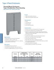
STANCHION<br />
STANCHION<br />
EVMJ4 1 1/4" HUB<br />
116EX-S 1 1/4" HUB<br />
CEILING<br />
116EX-C EV22 3/4" HUB<br />
PENDANT<br />
PENDANT<br />
116EX-P EVMP3 3/4" 3/4" HUB HUB<br />
116EX-C EV22<br />
WALL<br />
116EX-B EV87 3/4" 3/4" HUB<br />
116 EX SERIES HOUSING AND AND GLOBE GLOBE<br />
ASSEMBLY WITH GUARD<br />
Figure 1. Mounting Options<br />
Description<br />
The EXR301 Series 120V AC rotating signaling appliances<br />
are intended for general utility signaling use. They are<br />
UL and cUL listed for use in Class I, Division 1, Group C<br />
and D, Class I, Division 2, Group A, B, C and D, Class II,<br />
Division 1, Group E, F and G, Class II, Division 2, Group F<br />
and G, and Class III Division 1 and 2 hazardous locations<br />
with operating temperature codes per following chart.<br />
The beacons are UL and cUL Listed as Type 3R, 4X, and<br />
Marine enclosures.<br />
The rotating assembly is driven by a motor that revolves<br />
75 times per minute.<br />
The beacons are available with pendant, bracket, ceiling<br />
or stanchion mounting modules. See Figure 1.<br />
Installation<br />
<strong>WARNING</strong><br />
To reduce the risks of ignition of hazardous atmospheres<br />
and shock, do not apply power to the unit<br />
until installation has been completed and unit is<br />
tightly assembled and secured.<br />
Install this unit in accordance with the applicable requirements<br />
in the latest edition of the National Electrical Code<br />
and Canadian Electrical Code.<br />
1. Mount using the following applicable method.<br />
a. Pendant Mount Models (Figure 2): Install the<br />
catalog number EVMP3, pendant mounting<br />
module, to the main housing. Install explosionproof<br />
hanger box (not supplied). Secure 3/4"<br />
(19 mm) NPT threaded conduit (not supplied) to<br />
the box. Install the unit on the conduit. Proceed<br />
to step 2.<br />
b. Ceiling Mount Models (Figure 3): Mount the<br />
catalog number EV22, ceiling/wall mounting<br />
module, using appropriate hardware (not<br />
supplied) suitable for the mounting surface.<br />
Proceed to step 2.<br />
c. Wall Mount Models (Figure 4): Install the<br />
catalog number EV22 ceiling/wall mouting<br />
module using appropriate hardware (not<br />
supplied) for the mounting surface. Install the<br />
catalog number EV87 wall mounting elbow<br />
to the wall box. Run the unit's wiring through<br />
the elbow to the wall box. Proceed to step 2.<br />
d. Stanchion Mount Models (Figure 5): Install the<br />
catalog number EVMJ4, stanchion mounting<br />
module, to the main housing. Run the unit's wires<br />
through the 1 1/4" conduit to the appropriate<br />
junction box. Install the unit on the conduit.<br />
Proceed to step 2.<br />
2. Connect field earth ground wire to ground screw or<br />
earth ground via conduit system.<br />
3. Using wire nuts, connect the incoming (+) or white<br />
wire to the unit's two (+) white wires and the incoming<br />
(-) or black wire to the unit's two (-) black wires. See<br />
Table 2 for required supply wire temperature ratings.<br />
4. As appropriate, install the fixture on the mounting<br />
module.<br />
<strong>WARNING</strong><br />
To reduce the risk of ignition of hazardous atmospheres<br />
and shock, keep assembly tightly closed<br />
when circuits are energized.<br />
5. Apply power to the unit and ensure proper function.<br />
IF 1491 • 11/04 Copyright © <strong>Cooper</strong> <strong>Industries</strong>, Inc. Page 1
6 3/4"<br />
4"<br />
4"<br />
12"<br />
12 3/4"<br />
5/16"<br />
1"<br />
13"<br />
13 3/4"<br />
7 1/4"<br />
7 1/4"<br />
Figure 2. Detail of Pendant Mounting<br />
Figure 3. Detail of Ceiling Mounting<br />
Maintenance<br />
Disassemble the unit as follows (Figure 6):<br />
<strong>WARNING</strong><br />
To reduce the risk of ignition of hazardous atmospheres<br />
and shock, keep assembly tightly closed<br />
when circuits are energized.<br />
To reduce the risk of ignition of hazardous atmospheres<br />
and shock, disconnect from the supply and<br />
circuit and allow five (5) minutes for stored energy to<br />
dissipate before disassembling the unit.<br />
counterclockwise direction. Remove the ring and<br />
globe assembly.<br />
3. Refer to Table 1 for the correct replacement catalog<br />
number and replace the necessary part.<br />
4. To replace, simply screw the unit on until it seats firmly<br />
onto its gasket. Tighten the unit another 1/8 to 1/4<br />
turn. Tighten the setscrew.<br />
5. Reinstall the guard, where applicable, and secure using<br />
the three supplied screws.<br />
6. After the unit is assembled, apply power and make<br />
sure the unit functions properly.<br />
1. Loosen the (3) guard screws and remove the guard.<br />
2. Loosen the globe and ring assembly set screw. Insert<br />
a suitable tool into the notches in the globe and ring<br />
assembly and loosen the assembly by prying in a<br />
IF 1491 • 11/04 Copyright © <strong>Cooper</strong> <strong>Industries</strong>, Inc. Page 2
12 9/16"<br />
13 1/4"<br />
9 7/16"<br />
6 3/4"<br />
1"<br />
4"<br />
1/4"<br />
4"<br />
16 13/16"<br />
16 1/16"<br />
5/16"<br />
12 3/4"<br />
13 1/2"<br />
1 1/4"<br />
Conduit<br />
Figure 4. Detail of Wall Bracket Mounting<br />
Figure 5. Detail of Stanchion Mounting<br />
Strobe Tube<br />
Globe & Ring<br />
Assembly<br />
Guard<br />
Figure 6. Disassembly of the EXR301 Hazard-Gard<br />
IF 1491 • 11/04 Copyright © <strong>Cooper</strong> <strong>Industries</strong>, Inc. Page 3
Table 1. EXR301 Hazard-Gard<br />
Catalog Electrical Conduit Lamp<br />
Description Number Ratings Size Replacement<br />
Beacon Less EXR301***/120 120V 50/60 Hz N/A 50LMP-40WH<br />
Mounting Module 0.35A or<br />
Ind. Trade No.<br />
25T8DC<br />
Ceiling/Wall EV22 N/A 3/4" NPT N/A<br />
Mounting Module<br />
Pendant EVMP3 N/A 3/4" NPT N/A<br />
Mounting Module<br />
Stanchion EVMJ4 N/A 1 1/4" NPT N/A<br />
Mounting Module<br />
Wall Bracket EV87 N/A N/A N/A<br />
Mounting Elbow<br />
*Letter in this position denotes color of the globe: A - amber, B - blue, C - clear, G - green, R - red or<br />
M - magenta<br />
Table 2. Ratings<br />
Operating Temperature<br />
Ambient Supply Wire Class I, Div. 2 Class I, Div. 1 & 2 Class II & III, Div. 1 Class II & III, Div. 2<br />
Temp. Temp. Marking Groups A, B Groups C, D Groups E, F, G Group G<br />
40°C 75°C T1 (450°C) T6 (85°C) T4A (120°C) T4A (120°C)<br />
55°C 90°C T1 (450°C) T5 (100°C) T4 (135°C) T4 (135°C)<br />
65°C 105°C T1 (450°C) T5 (100°C) T4 (135°C) T4 (135°C)<br />
All statements, technical information and recommendations contained herein are based on information and tests we believe to be<br />
reliable. The accuracy or completeness thereof are not guaranteed. In accordance with Crouse-Hinds “Terms and Conditions of Sale”,<br />
and since conditions of use are outside our control, the purchaser should determine the suitability of the product for his intended use<br />
and assumes all risk and liability whatsoever in connection therewith.<br />
<strong>Cooper</strong> <strong>Industries</strong> Inc.<br />
Crouse-Hinds Division<br />
PO Box 4999, Syracuse, New York 13221 • U.S.A.<br />
Copyright© 2004, <strong>Cooper</strong> <strong>Industries</strong>, Inc.<br />
IF 1491<br />
Revision 1<br />
New 11/04<br />
P/N 3100910
P/N 3100910 (IF 1491) OFFSET SPEC<br />
INSTALLATION INSTRUCTIONS FOR CROUSE-<br />
HINDS CATALOG SERIES EXR301 HAZARD-GARD<br />
FOR USE IN<br />
HAZARDOUS LOCATIONS<br />
(1) 11" X 17" SHEET PRINTED BOTH SIDES. FOLD<br />
THREE TIMES TO DIMENSIONS SHOWN ON DETAIL<br />
WITH PART NUMBER ON THE OUTSIDE.<br />
MATERIAL: STANDARD WHITE OFFSET STOCK<br />
CHARACTERS: TO BE BLACK ON WHITE BACK-<br />
GROUND<br />
NOTE: MECHANICALS HAVE ALREADY BEEN<br />
REDUCED TO ACTUAL SIZE.<br />
IF 1491 11/04<br />
FOLD DETAIL REFERENCE ONLY<br />
ECN: 04-C1727<br />
Issue: 01<br />
File: 3100910<br />
Approved by: KRT