PST 6000.XXX Thyristor Power Unit Technical ... - Bosch Rexroth
PST 6000.XXX Thyristor Power Unit Technical ... - Bosch Rexroth
PST 6000.XXX Thyristor Power Unit Technical ... - Bosch Rexroth

You also want an ePaper? Increase the reach of your titles
YUMPU automatically turns print PDFs into web optimized ePapers that Google loves.
<strong>PST</strong> 6000<br />
<strong>PST</strong> <strong>6000.XXX</strong> <strong>Thyristor</strong> <strong>Power</strong> <strong>Unit</strong><br />
with integrated control function<br />
<strong>Technical</strong> Information<br />
Edition<br />
101
<strong>PST</strong> 6000<br />
<strong>PST</strong> <strong>6000.XXX</strong> <strong>Thyristor</strong> <strong>Power</strong> <strong>Unit</strong><br />
with integrated control function<br />
<strong>Technical</strong> Information<br />
1070 080 058-101 (2001.04) GB<br />
Reg. no. 16149-03<br />
E 2000-2001<br />
This manual is the exclusive property of Robert <strong>Bosch</strong> GmbH,<br />
also in the case of Intellectual Property Right applications.<br />
Without their consent it may not be reproduced or given to third parties.<br />
Discretionary charge 10.-
Contents<br />
V<br />
Contents<br />
Page<br />
1 Safety instructions . . . . . . . . . . . . . . . . . . . . . . . . . . . . 1-1<br />
1.1 Safety instructions and symbols attached to the product . . . . . . 1-1<br />
1.2 Safety instructions and symbols used in this manual . . . . . . . . . 1-2<br />
1.3 Intended use . . . . . . . . . . . . . . . . . . . . . . . . . . . . . . . . . . . . . . . . . . . 1-3<br />
1.4 No admittance for persons fitted with cardiac pacemakers . . . . 1-4<br />
1.5 Qualified personnel . . . . . . . . . . . . . . . . . . . . . . . . . . . . . . . . . . . . . . 1-5<br />
1.6 Installation and assembly . . . . . . . . . . . . . . . . . . . . . . . . . . . . . . . . 1-6<br />
1.7 Electrical connection . . . . . . . . . . . . . . . . . . . . . . . . . . . . . . . . . . . . . 1-9<br />
1.8 Ensuring EMC of the completely assembled system . . . . . . . . . 1-12<br />
1.9 Operation of the thyristor power units . . . . . . . . . . . . . . . . . . . . . . 1-13<br />
1.10 Retrofits and modifications by the user . . . . . . . . . . . . . . . . . . . . . 1-14<br />
1.11 Maintenance, repair . . . . . . . . . . . . . . . . . . . . . . . . . . . . . . . . . . . . . 1-15<br />
1.12 Working safely . . . . . . . . . . . . . . . . . . . . . . . . . . . . . . . . . . . . . . . . . . 1-16<br />
2 Setup . . . . . . . . . . . . . . . . . . . . . . . . . . . . . . . . . . . . . . . . 2-1<br />
2.1 Features . . . . . . . . . . . . . . . . . . . . . . . . . . . . . . . . . . . . . . . . . . . . . . . 2-1<br />
2.2 Modules and components . . . . . . . . . . . . . . . . . . . . . . . . . . . . . . . . 2-2<br />
2.3 Function . . . . . . . . . . . . . . . . . . . . . . . . . . . . . . . . . . . . . . . . . . . . . . . 2-4<br />
2.4 Monitoring . . . . . . . . . . . . . . . . . . . . . . . . . . . . . . . . . . . . . . . . . . . . . . 2-4<br />
3 Notes on Rating . . . . . . . . . . . . . . . . . . . . . . . . . . . . . . 3-1<br />
4 Commissioning . . . . . . . . . . . . . . . . . . . . . . . . . . . . . . . 4-1<br />
5 Maintenance . . . . . . . . . . . . . . . . . . . . . . . . . . . . . . . . . . 5-1<br />
6 Malfunction . . . . . . . . . . . . . . . . . . . . . . . . . . . . . . . . . . 6-1<br />
7 Type overview . . . . . . . . . . . . . . . . . . . . . . . . . . . . . . . . 7-1<br />
7.1 Features . . . . . . . . . . . . . . . . . . . . . . . . . . . . . . . . . . . . . . . . . . . . . . . 7-1<br />
8 <strong>PST</strong> 6100.XXX L . . . . . . . . . . . . . . . . . . . . . . . . . . . . . . 8-1<br />
8.1 <strong>PST</strong> 6100.XXX L overview . . . . . . . . . . . . . . . . . . . . . . . . . . . . . . . 8-1<br />
8.2 Explanation of drawings . . . . . . . . . . . . . . . . . . . . . . . . . . . . . . . . . . 8-1<br />
8.3 <strong>PST</strong> 6100.XXX L front panel . . . . . . . . . . . . . . . . . . . . . . . . . . . . . . 8-2<br />
8.4 <strong>Technical</strong> data, <strong>PST</strong> 6100.XXX L . . . . . . . . . . . . . . . . . . . . . . . . . . 8-4<br />
8.5 Dimensioned drawing, <strong>PST</strong> 6100.XXX L . . . . . . . . . . . . . . . . . . . 8-5<br />
8.6 Electrical connection, <strong>PST</strong> 6100.XXX L . . . . . . . . . . . . . . . . . . . . 8-6<br />
8.7 Load diagram, <strong>PST</strong> 6100.XXX L . . . . . . . . . . . . . . . . . . . . . . . . . . 8-7<br />
8.8 Accessories, <strong>PST</strong> 6100.XXX L . . . . . . . . . . . . . . . . . . . . . . . . . . . . 8-8<br />
8.8.1 Dimensioned drawing, accessories kit . . . . . . . . . . . . . . . . . . . . . 8-8<br />
8.9 Ordering accessories . . . . . . . . . . . . . . . . . . . . . . . . . . . . . . . . . . . . 8-10<br />
1070 080 058-101 (2001.04) GB
VI<br />
Contents<br />
Page<br />
9 <strong>PST</strong> 6250.XXX L . . . . . . . . . . . . . . . . . . . . . . . . . . . . . . 9-1<br />
9.1 <strong>PST</strong> 6250.XXX L overview . . . . . . . . . . . . . . . . . . . . . . . . . . . . . . . 9-1<br />
9.2 Explanation of drawings . . . . . . . . . . . . . . . . . . . . . . . . . . . . . . . . . . 9-1<br />
9.3 <strong>PST</strong> 6250.XXX L front panel . . . . . . . . . . . . . . . . . . . . . . . . . . . . . . 9-2<br />
9.4 <strong>Technical</strong> data, <strong>PST</strong> 6250.XXX L . . . . . . . . . . . . . . . . . . . . . . . . . . 9-4<br />
9.5 Dimensioned drawing, <strong>PST</strong> 6250.XXX L . . . . . . . . . . . . . . . . . . . 9-5<br />
9.6 Electrical connection, <strong>PST</strong> 6250.XXX L . . . . . . . . . . . . . . . . . . . . 9-6<br />
9.7 Load diagram, <strong>PST</strong> 6250.XXX L . . . . . . . . . . . . . . . . . . . . . . . . . . 9-7<br />
9.8 Accessories, <strong>PST</strong> 6250.XXX L . . . . . . . . . . . . . . . . . . . . . . . . . . . . 9-8<br />
9.8.1 Dimensioned drawing, accessories kit . . . . . . . . . . . . . . . . . . . . . 9-8<br />
9.9 Ordering accessories . . . . . . . . . . . . . . . . . . . . . . . . . . . . . . . . . . . . 9-10<br />
10 CE declaration of conformity . . . . . . . . . . . . . . . . . . 10-1<br />
A Annex . . . . . . . . . . . . . . . . . . . . . . . . . . . . . . . . . . . . . . . . A-1<br />
A.1 Index . . . . . . . . . . . . . . . . . . . . . . . . . . . . . . . . . . . . . . . . . . . . . . . . . . A-1<br />
1070 080 058-101 (2001.04) GB
Safety instructions 1-1<br />
1 Safety instructions<br />
The products described were developed, manufactured and tested in compliance<br />
with the fundamental safety requirements of the EU machine directive.<br />
These products normally pose no danger to persons or property if used<br />
in accordance with the handling stipulations and safety notes prescribed for<br />
their configuration, mounting, and proper operation.<br />
Nevertheless, there is some residual risk!<br />
Therefore, you should read this manual before installing, connecting or commissioning<br />
the products. Store this manual in a place to which all users have<br />
access at any time!<br />
This manual describes the:<br />
D <strong>PST</strong> 6000 thyristor power units<br />
The functions of the integrated weld timer are described in a separate<br />
manual.<br />
1.1 Safety instructions and symbols attached to the product<br />
Warning of dangerous electrical voltage!<br />
Lug for connecting PE conductor only!<br />
1070 080 058-101 (2001.04) GB
1-2<br />
Safety instructions<br />
1.2 Safety instructions and symbols used in this manual<br />
DANGEROUS ELECTRICAL VOLTAGE<br />
This symbol is used to warn of dangerous electrical voltage. Failure to<br />
observe the instructions in this manual in whole or in part may result in personal<br />
injury.<br />
DANGER<br />
This symbol is used wherever insufficient or lacking compliance with instructions<br />
may result in personal injury.<br />
CAUTION<br />
This symbol is used wherever insufficient or lacking compliance with instructions<br />
may result in damage to equipment or data files.<br />
. Note: This symbol is used to draw the user’s attention to special circumstances.<br />
L<br />
This symbol is used if user activities are required.<br />
Modifications in this manual as compared to a previous edition are marked<br />
by black vertical bars in the margin.<br />
1070 080 058-101 (2001.04) GB
Safety instructions 1-3<br />
1.3 Intended use<br />
<strong>PST</strong> 6000 thyristor power units are designed for connection of welding transformers.<br />
These thyristor power units are designed for use in<br />
D resistance welding of metals and<br />
D are suitable for operation in industrial environments as per DIN EN<br />
50082-2 and 50081-2 on electromagnetic compatibility (EMC).<br />
They are not intended for any other use!<br />
DANGER<br />
Any use other than for the purpose indicated may result in personal<br />
injury of the user or third parties or in damage to equipment, the<br />
workpiece to be welded, or environmental damage.<br />
Therefore, our products must never be used for any other than their<br />
respective intended purpose!<br />
. Note: For operation in residential environments, in trade and commercial<br />
applications and small enterprises, an individual permit of the national<br />
authority or test institution is required; in Germany, please<br />
contact the Regulierungsbehörde für Telekommunikation und Post<br />
(RegTP) or its local branch offices.<br />
The faultless, safe functioning of the product requires proper transport, storage,<br />
erection and installation as well as careful operation.<br />
1070 080 058-101 (2001.04) GB
1-4<br />
Safety instructions<br />
1.4 No admittance for persons fitted with cardiac pacemakers<br />
DANGER<br />
WARNING for persons fitted with cardiac pacemakers!<br />
To protect persons fitted with cardiac pacemakers, noentry signs<br />
should be posted because pacemaker malfunction (missed pulses,<br />
total failure), pacemaker program interference or even program<br />
destruction is to be expected!!!<br />
. Note: We recommend that warning sings like the one shown below are<br />
posted at every entrance to manufacturing shops housing resistancewelding<br />
equipment:<br />
DIN 40023<br />
No entry for persons with cardiac<br />
pacemakers!<br />
Danger!<br />
1070 080 058-101 (2001.04) GB
Safety instructions 1-5<br />
1.5 Qualified personnel<br />
The requirements as to qualified personnel are based on the requirements<br />
profiles as defined by the ZVEI (Zentralverband Elektrotechnik und Elektronikindustrie<br />
- German Electrical and Electronic Manufacturers’ Association)<br />
and the VDMA (Verband deutscher Maschinen- und Anlagenbau -<br />
German Engineering Federation) in:<br />
Weiterbildung in der Automatisierungstechnik<br />
edited by: ZVEI and VDMA<br />
Maschinenbau Verlag<br />
Postfach 71 08 64<br />
D-60498 Frankfurt.<br />
This manual is designed for technicians and engineers with special welding<br />
training and skills. They must have a sound knowledge of the hardware components<br />
of the weld control system, the <strong>PST</strong> 6000 thyristor power units and<br />
the welding transformers.<br />
Interventions in the hardware and software of our products, unless described<br />
otherwise in this manual, are reserved to specialized <strong>Bosch</strong> personnel.<br />
Tampering with the hardware or software, ignoring warning signs attached to<br />
the components, or non-compliance with the warning notes given in this<br />
manual can result in serious bodily injury or property damage.<br />
Only skilled persons as defined in IEV 826-09-01 who are familiar with the<br />
contents of this manual may install and service the products described.<br />
Such personnel are<br />
D those who, being well trained and experienced in their field and familiar<br />
with the relevant standards, are able to analyze the work to be carried out<br />
and recognize any hazards.<br />
D those who have acquired the same amount of expert knowledge through<br />
years of experience that would normally be acquired through formal technical<br />
training.<br />
DANGER!<br />
An exception are persons with cardiac pacemakers!<br />
The strong magnetic fields occurring in resistance welding may affect<br />
the proper functioning of pacemakers. This may be fatal or cause<br />
serious personal injury!<br />
Therefore, persons with pacemakers must stay clear of resistance<br />
welding systems.<br />
We recommend that warning sings as per DIN 40023 are posted at every<br />
entrance to manufacturing shops housing resistance-welding<br />
equipment.<br />
Please note our comprehensive range of training courses. More information<br />
is available from our training center (Phone: +49 / 6062 / 78-258).<br />
1070 080 058-101 (2001.04) GB
1-6<br />
Safety instructions<br />
1.6 Installation and assembly<br />
DANGER<br />
Non-workmanlike installation or mounting may lead to personal injury<br />
or damage to property.<br />
Therefore, it is essential that you take the technical data (environmental<br />
conditions) into account for installation or mounting.<br />
Installation or mounting must be carried out by skilled personnel<br />
only.<br />
DANGER<br />
Insufficient degree of protection may be life-threatening or cause<br />
damage to property!<br />
The degree of protection of thyristor power units is IP 20. They must<br />
be installed in switchgear cubicles providing a degree of protection<br />
of no less than IP 54.<br />
DANGER<br />
Danger of injury and of damage to property through incorrect installation!<br />
Devices and, in particular, operating means, must be installed so as<br />
to be properly safeguarded against unintentional operation or contact.<br />
DANGER<br />
Risk of injury from sharp-edged sheet metal!<br />
Wear protective gloves!<br />
DANGER<br />
Danger of personal injury and damage to property through inadequate<br />
fastening!<br />
The place for installing the thyristor power units, and their method<br />
of fastening, must be suitable for their weight!<br />
Injuries and bruises may be caused by lifting weights which are too<br />
heavy or by sharp metal edges!<br />
Due to the heavy weight of individual modules several persons are<br />
required for installation and assembly.<br />
Wear safety shoes and safety gloves!<br />
1070 080 058-101 (2001.04) GB
Safety instructions 1-7<br />
DANGEROUS ELECTRICAL VOLTAGE<br />
Before the modules are installed, the respective mounting station<br />
must be safely isolated from supply and properly safeguarded to prevent<br />
unintentional or unauthorized reclosing.<br />
CAUTION<br />
Short circuits!<br />
When cut-outs are drilled or sawed in switchgear cubicles, metal<br />
burr may get into modules already installed there. Or, when cooling<br />
water lines are connected, water may leak into the thyristor power<br />
units installed.<br />
The possibility of short circuits occurring in the process or even the<br />
destruction of the devices cannot be entirely ruled out.<br />
Therefore, guard any existing modules well before you install a new<br />
module! Any and all warranty excluded in case of non-compliance.<br />
CAUTION<br />
Heat accumulation!<br />
<strong>Thyristor</strong> power units must be mounted with a minimum clearance<br />
of 100 mm on top and at the bottom. Without this minimum clearance,<br />
heat may accumulate and cause power unit failure.<br />
CAUTION<br />
In the case of aircooled thyristor power units, the temperature inside<br />
the housing must stay within the specified range. <strong>Thyristor</strong> power<br />
units must always be operated under forcedair cooling conditions.<br />
Convection cooling will not be sufficient!<br />
CAUTION<br />
Leaks in the cooling water circuit may cause consequential damage!<br />
Cooling water leaks may damage adjacent components. Therefore,<br />
when mounting water-cooled modules, always ensure that other devices<br />
in the switchgear cabinet are well protected against leaking<br />
cooling water.<br />
1070 080 058-101 (2001.04) GB
1-8<br />
Safety instructions<br />
CAUTION<br />
Damage to property through inappropriate or insufficient cooling of<br />
the thyristor power units!<br />
Water-cooled thyristor power units may only be operated when the<br />
cooling water circuit is active! Condensation on water-carrying components<br />
must be prevented.<br />
Damage to property through insufficient water quality in the cooling<br />
water circuit!<br />
Deposits in the cooling system may reduce the water flow, thus impairing<br />
the performance of the cooling system with time.<br />
Therefore, you should ensure that your cooling water has the following<br />
properties:<br />
D pH value : 7 to 8.5<br />
D Degree of hardness D max : 10 German degrees<br />
(1 German degree = 1.25 British degrees = 1.05 US degrees =<br />
1.8 French degrees)<br />
D Chlorides : max. 20 mg/l<br />
D Nitrates : max. 10 mg/l<br />
D Sulfates : max. 100 mg/l<br />
D Insoluble substances : max. 250 mg/l<br />
Tap water usually meets these requirements. However, an algicide<br />
should be added.<br />
L<br />
L<br />
Make sure that all contact surfaces are bright, i.e. free of paint, plastic coating<br />
or dirt/oxidation.<br />
Mount the device in a vertical position.<br />
1070 080 058-101 (2001.04) GB
Safety instructions 1-9<br />
1.7 Electrical connection<br />
DANGEROUS ELECTRICAL VOLTAGE<br />
The mains voltage is associated with many dangers!<br />
Possible consequences of improper handling include death or most<br />
severe injuries (personal injuries) and damage to property. For this<br />
reason, the electrical connection must always be made by an electrical<br />
expert in compliance with the valid safety regulations, the mains<br />
voltage and the maximum current consumption of the individual<br />
units of the equipment.<br />
The mains voltage must match the nominal voltage given on the<br />
nameplate of the product!<br />
The equipment must be appropriately fused on the supply side!<br />
Prior to connecting a thyristor power unit, the following must be<br />
strictly observed:<br />
D<br />
D<br />
D<br />
D<br />
D<br />
<strong>Power</strong> OFF.<br />
Provide a safeguard to prevent unintentional reclosing.<br />
Verify that the system is safely isolated from supply and<br />
de-energized.<br />
Connect to earth and short circuit.<br />
Cover up or safeguard all live parts.<br />
DANGEROUS ELECTRICAL VOLTAGE<br />
Handling live parts at mains voltage may result in death, severe<br />
bodily injury or considerable damage to property unless appropriate<br />
precautions are taken.<br />
For this reason, the electrical connection must always be made by<br />
an electrical expert in compliance with the valid safety regulations,<br />
the mains voltage and the maximum current consumption of the individual<br />
units of the equipment.<br />
Incorrect mains voltage may render the system dangerous or cause<br />
electrical component failure!<br />
Therefore, please ensure the following:<br />
D<br />
D<br />
D<br />
D<br />
The mains voltage must match the nominal voltage given on the<br />
nameplate of the product!<br />
Mains voltage fluctuation or variation from the nominal voltage<br />
must be within the specified tolerance range (see <strong>Technical</strong> Data).<br />
The equipment must be appropriately fused on the mains side!<br />
Proper and well insulated tools must be used for handling electric<br />
connections!<br />
1070 080 058-101 (2001.04) GB
1-10<br />
Safety instructions<br />
DANGEROUS ELECTRICAL VOLTAGE<br />
Danger of life through insufficient protective conductor system!<br />
The thyristor power units must be connected to the protective earthing<br />
(PE) circuit of the system. Please ensure that the cross-sectional<br />
area of cables used for protective conductor wiring is sufficiently<br />
large. The electrical continuity of the protective earthing circuit must<br />
be verified in accordance with EN 60204 Part 1.<br />
DANGEROUS ELECTRICAL VOLTAGE<br />
<strong>Thyristor</strong> power units may be operated in earth neutral systems only.<br />
Protective grounding is the only protective measure permitted as per<br />
EN 50 178 (DIN VDE 0160)!<br />
DANGEROUS ELECTRICAL VOLTAGE<br />
Operation in unbalanced networks (only one network phase<br />
grounded) is not permitted.<br />
. Note: It is recommended that the whole welding system be operated<br />
within a separate welding power network.<br />
CAUTION<br />
Connecting lines and signal lines must be laid so as to avoid negative<br />
effects on the function of the units through capacitive or inductive<br />
interference!<br />
Interference is frequently coupled and de-coupled in long cables.<br />
Therefore, thyristor power unit cables and control cables must be<br />
routed separately. The influence of interfering cables on cables susceptible<br />
to interference can be minimized by keeping the following<br />
distances:<br />
D > 100 mm if cables are run in parallel for < 10 m,<br />
D > 250 mm if cables are run in parallel for > 10 m.<br />
The thyristor power unit should be mounted close to the welding<br />
systems so as to avoid cable lengths of more than 25 m.<br />
CAUTION<br />
Connection cables may come off and apply dangerous voltage to<br />
system components!<br />
It is crucial that cables are properly fixed.<br />
1070 080 058-101 (2001.04) GB
Safety instructions 1-11<br />
L PE connection : Connect to a central earth point. Make sure that cable<br />
cross-sectional areas are sufficiently large!<br />
L<br />
All conductor cross-sections must be large enough for the loads to be connected.<br />
L U1 connection : Connect to L1 system phase.<br />
L V1 connection : Connect to L2 system phase.<br />
L U2 and V2 welding transformer outputs : Connect to welding transformer.<br />
1070 080 058-101 (2001.04) GB
1-12<br />
Safety instructions<br />
1.8 Ensuring EMC of the completely assembled system<br />
. Note: The completely assembled system with the welding transformer<br />
complies with prEN 50240, the EMC product standard for resistance<br />
welding systems, and EN 55011 (October 1997), EMC product family<br />
standard class A, group 2, rated current > 100 A.<br />
D Only for industrial applications.<br />
D Safe clearance from residential areas 30 m.<br />
D Safe clearance to communication systems (wireless, telephone) 10 m.<br />
D Cable length of mains feeder 10 m.<br />
D Interference suppression measures: When switchgear cabinet doors are<br />
open, operation of radio devices or cell phones is permitted only beyond<br />
a safe clearance of 2 m.<br />
1070 080 058-101 (2001.04) GB
Safety instructions 1-13<br />
1.9 Operation of the thyristor power units<br />
DANGER<br />
Danger of personal injury and damage to property if devices are operated<br />
before they have been properly installed!<br />
The devices are designed to be installed in housings or switchgear<br />
cabinets and must not be operated unless properly installed and<br />
switchgear cabinet doors are closed!<br />
DANGER<br />
Danger of personal injury and damage to property through missing<br />
or false interpretation of fault messages!<br />
Therefore, closing of the temperature contact (thermostatic switch,<br />
break contact) must inhibit the connected timer!<br />
As regards fault analysis, see also the section on ”Malfunction”.<br />
DANGER<br />
Danger of bruises through electrode movement!<br />
All users, line designers, welding machine manufacturers and welding<br />
gun producers are obliged to connect the output signal of the<br />
<strong>Bosch</strong> weld timer which initiates the electrode movement so that the<br />
applicable safety regulations are complied with.<br />
The risk of bruises can be considerably reduced by means of, e.g.,<br />
two-handed start, guard rails, light barriers etc.<br />
CAUTION<br />
Damage to property through insufficient cooling of the modules!<br />
Ensure that the modules are properly cooled during operation. Condensation<br />
on water-carrying components must be prevented. In the<br />
case of air-cooled thyristor power units, the temperature inside the<br />
mounting station must remain in the specified range. In the case of<br />
water-cooled thyristor power units, the maximum permitted coolingwater<br />
temperature must not be exceeded.<br />
CAUTION<br />
Damage to property through excessive welding current!<br />
The maximum welding current depends on the thyristor unit and the<br />
welding transformer in use. It must not be exceeded.<br />
Therefore, the user must check the load in each case. See also the<br />
section on ”Load diagrams”.<br />
Any and all warranty excluded in case of non-compliance.<br />
1070 080 058-101 (2001.04) GB
1-14<br />
Safety instructions<br />
1.10 Retrofits and modifications by the user<br />
DANGER<br />
Retrofits or modifications may have negative effects on the safety of<br />
the unit!<br />
Product modification may cause death, severe or light personal<br />
injury, damage to property or environmental damage.<br />
Therefore, please contact us prior to making any modification. This<br />
is the only way to determine whether modified components are<br />
suitable for use with our products.<br />
1070 080 058-101 (2001.04) GB
Safety instructions 1-15<br />
1.11 Maintenance, repair<br />
DANGEROUS ELECTRICAL VOLTAGE<br />
Prior to any maintenance work - unless described otherwise - the<br />
system must always be switched off!<br />
In the event of necessary measurement or test procedures on the active<br />
system, these have to be performed by skilled electrical personnel.<br />
In any case, suitable insulated tools must be used!<br />
DANGER<br />
Danger of life through inappropriate EMERGENCY-STOP facilities!<br />
EMERGENCY-STOP facilities must be operative in all modes of the<br />
system. Releasing the EMERGENCY-STOP facility must by no means<br />
result in an uncontrolled restart of the system! First check the EMER-<br />
GENCY-STOP circuit, then switch the unit on!<br />
DANGER<br />
Danger of explosion of batteries!<br />
Do not forcefully open batteries, do not attempt to charge, solder or<br />
incinerate the battery.<br />
Empty batteries should always be replaced by new ones!<br />
The applicable regulations on the disposal of empty batteries or accumulators<br />
must be observed.<br />
DANGER<br />
The right to perform repair/maintenance work on the components of<br />
the thyristor power units is reserved to the BOSCH service department<br />
or to repair/maintenance units authorized by BOSCH!<br />
CAUTION<br />
Only use spare parts approved by BOSCH!<br />
1070 080 058-101 (2001.04) GB
1-16<br />
Safety instructions<br />
1.12 Working safely<br />
DANGER<br />
During operation of the welding equipment welding splashes are to<br />
be expected! They may cause eye injuries or burns.<br />
Therefore:<br />
D wear protective goggles<br />
D wear protective gloves<br />
D wear flame-retardant clothes<br />
DANGER<br />
Danger of injury from sheet metal edges and danger of burns from<br />
weld metal!<br />
Therefore: - wear protective gloves<br />
DANGER<br />
In the environment of resistance welding systems, magnetic field<br />
strengths have to be expected which are above the limit values specified<br />
in VDE 0848 Part 4. Especially if manual guns are used, the limit<br />
values for extremities may be exceeded.<br />
In cases of doubt, you should measure the field strength and take<br />
additional measures to ensure safety and health at work.<br />
CAUTION<br />
The strong magnetic fields occurring in the resistance welding process<br />
may cause permanent damage to wrist watches, pocket<br />
watches, or cards with magnetic stripes (e.g. EC cards).<br />
Therefore, you should not carry any such items on you when working<br />
in the immediate vicinity of the welding equipment.<br />
1070 080 058-101 (2001.04) GB
Setup 2-1<br />
2 Setup<br />
2.1 Features<br />
D<br />
D<br />
D<br />
D<br />
D<br />
D<br />
D<br />
D<br />
D<br />
D<br />
D<br />
Integrated control functionality<br />
Integrated weld timer<br />
Flexible parallel and/or serial I/O interfaces<br />
Fieldbus interfaces for communication<br />
Integrated control and monitoring functions<br />
Control functionality separate from monitoring functionality<br />
Air or water cooled<br />
Less cabling required due to system component integration<br />
Functionality designed for welding quality optimization<br />
Easily integrated into a portable welding box system<br />
(SCHWEISSKOFFER)<br />
BOS-5000 operator interface provides for easy programming, operation<br />
and diagnostics<br />
<strong>PST</strong> <strong>6000.XXX</strong> thyristor power unit<br />
1070 080 058-101 (2001.04) GB
2-2<br />
Setup<br />
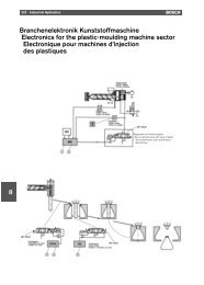
2.2 Modules and components<br />
The <strong>PST</strong> 6000 thyristor power units serve to control the welding transformers.<br />
Integrated features:<br />
D the weld timer (central processing unit, CPU)<br />
D one slot for the type-specific I/O interface<br />
D one slot for the field bus module for programming (optional)<br />
D one slot for retrofitting a quality module (optional)<br />
<strong>PST</strong> 6100.XXX L<br />
Mains<br />
V1<br />
U1<br />
Heat sink<br />
D - 64711 Erbach 107 Made in Germany<br />
U1 V1<br />
U2 V2<br />
U2<br />
A<br />
D<br />
D<br />
R<br />
type-specific I/O system<br />
Slot for field bus module<br />
Slot for Q<br />
module<br />
V24<br />
Field bus for progr. (option)<br />
BOS-5000<br />
BOS-5000<br />
Local PC:<br />
• programming,<br />
• logging,<br />
• diagnostics,<br />
• fault display<br />
Host PC:<br />
• programming,<br />
• logging,<br />
• diagnostics,<br />
• fault display<br />
V2<br />
Current sensor<br />
(toroid)<br />
Pressure control<br />
valve<br />
Solenoid<br />
Electrodes<br />
Welding transformer<br />
Setup for welding<br />
1070 080 058-101 (2001.04) GB
Setup 2-3<br />
Welding transformer<br />
U2<br />
V1<br />
U1<br />
V2<br />
<strong>Thyristor</strong> power unit<br />
Mains transformer<br />
Firing<br />
transformer<br />
Measuring<br />
transformer<br />
Synchronization<br />
voltage<br />
27 VAC<br />
Firing<br />
5 kHz<br />
Weld timer (CPU)<br />
UPR<br />
Feedback<br />
24 VAC<br />
Temperature<br />
message<br />
Stop circuit<br />
24VDC supply<br />
external<br />
device Shunt trip Pressure<br />
Transformer<br />
temperature<br />
current sensor<br />
type-specific<br />
I/O interface<br />
prepared for<br />
quality module<br />
Field bus module<br />
for<br />
programming<br />
(optional)<br />
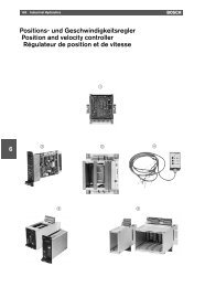
Block diagram of a thyristor power unit<br />
1070 080 058-101 (2001.04) GB
2-4<br />
Setup<br />
2.3 Function<br />
The thyristor power unit is designed for alternating current resistance welding.<br />
Key components of an AC welding system are the thyristor power unit,<br />
the weld timer and the welding transformer.<br />
The figure below shows the basic functional design.<br />
50/60 Hz two-phase alternating current<br />
50/60 Hz<br />
Timer<br />
<strong>Thyristor</strong><br />
power unit<br />
Welding<br />
transformer<br />
Welding<br />
apparatus<br />
Basic functional design of the AC welding process<br />
2.4 Monitoring<br />
In order to ensure high operational reliability, various monitoring functions<br />
are incorporated in the <strong>PST</strong> 6000 thyristor power unit.<br />
There is a thermostatic switch to signal any overload on the thyristor power<br />
unit to the weld timer.<br />
The weld timer will then output a ”<strong>Thyristor</strong> unit fault” message.<br />
When the fault has been cleared, the error message is reset as follows:<br />
D with the reset button on the weld timer front panel<br />
D by an input signal for acknowledgement (type-specific)<br />
D by an input on the BOS-5000 operator interface<br />
D by an input on the <strong>Bosch</strong> operator terminal (BT)<br />
1070 080 058-101 (2001.04) GB
Notes on Rating 3-1<br />
3 Notes on Rating<br />
The load capability of a thyristor power unit is always predefined by the type<br />
designation indicating the specific maximum welding transformer rating.<br />
CAUTION<br />
Overloading may cause damage to the thyristor power unit!<br />
Always check the actual load applied on the thyristor power unit! Any<br />
and all warranty excluded in case of damage caused by overload.<br />
To check the actual load, use the load diagram. It shows the<br />
D output currents (I PRIM in A) relative to<br />
D the duty cycle (ED in %) at<br />
D maximum ambient temperature (in °C)<br />
that can be switched by the <strong>PST</strong> 6000 thyristor power unit.<br />
The weld time t s and the overall weld cycle duration t sp must be known to<br />
determine the duty cycle.<br />
t s<br />
t sp<br />
Weld time and overall weld cycle duration<br />
The duty cycle is computed as follows:<br />
t s<br />
ED = * 100%<br />
t sp<br />
Example:<br />
In the graph shown above, the weld time is 2 periods<br />
and the overall weld cycle duration is 4 periods.<br />
This results in a duty cycle ED = 50%.<br />
2 per.<br />
ED = • 100% = 50%<br />
4 per.<br />
. Note: If different weld times or overall weld cycle times occur on a<br />
machine, the longest weld time and the shortest overall weld cycle<br />
time (to be determined, if required, by adding the longest weld time to<br />
the shortest cool time) must be used for calculating the duty cycle!<br />
When you have calculated the duty cycle, you can use load diagrams to<br />
verify the proper selection of the thyristor power unit.<br />
1070 080 058-101 (2001.04) GB
3-2<br />
Notes on Rating<br />
Notes:<br />
1070 080 058-101 (2001.04) GB
Commissioning 4-1<br />
4 Commissioning<br />
DANGEROUS ELECTRICAL VOLTAGE<br />
Danger of life in case of contact with live parts!<br />
Upon commissioning, the thyristor power unit is energized!<br />
CAUTION<br />
Cooling!<br />
Please make sure that there is sufficient cooling capacity.<br />
In the case of water cooled thyristor power units, ensure that the<br />
cooling water inlet connection is turned on and check the water temperature.<br />
Any and all warranty excluded in case of non-compliance.<br />
D<br />
D<br />
D<br />
D<br />
D<br />
D<br />
D<br />
D<br />
D<br />
Check the mechanical system of the welding outfit.<br />
Check the electrical installation.<br />
Check the auxiliary equipment:<br />
D pneumatic system<br />
D cooling water or cooling system.<br />
Check the operability of the emergency-stop devices.<br />
Cutting in the thyristor power unit:<br />
D Apply mains voltage.<br />
D The thyristor power unit starts working. The green ”<strong>Power</strong>” LED on the<br />
front panel of the weld timer (CPU) lights up.<br />
Check power supply and 24 V DC supply.<br />
Check peripheral I/O signals:<br />
D sensor signals,<br />
D communication with other weld timers.<br />
Check weld programs (for programmed current values and weld times).<br />
Cutting off the thyristor power unit:<br />
D Verify the safe isolation from supply.<br />
1070 080 058-101 (2001.04) GB
4-2<br />
Commissioning<br />
Notes:<br />
1070 080 058-101 (2001.04) GB
Maintenance 5-1<br />
5 Maintenance<br />
DANGEROUS ELECTRICAL VOLTAGE<br />
All maintenance work must be carried out by skilled electricians in<br />
compliance with the valid safety regulations, the mains voltage and<br />
the maximum current input values of the individual system components.<br />
Prior to connecting a thyristor power unit, the following must be<br />
strictly observed:<br />
D <strong>Power</strong> OFF.<br />
D Provide a safeguard to prevent unintentional reclosing.<br />
D Verify the safe isolation from supply.<br />
D Connect to earth and short circuit.<br />
D Cover up or safeguard all live parts.<br />
DANGEROUS ELECTRICAL VOLTAGE<br />
Prior to any maintenance work - unless described otherwise - the<br />
system must always be switched off!<br />
In the event of necessary measurement or test procedures at the active<br />
system, the applicable safety and accident prevention regulations<br />
must be strictly observed. In any case, suitable insulated tools<br />
must be used!<br />
Danger of life through inappropriate EMERGENCY-STOP facilities!<br />
EMERGENCY-STOP facilities must be operative in all modes of the<br />
system. Releasing the EMERGENCY-STOP facility must by no means<br />
result in an uncontrolled restart of the system!<br />
Danger of explosion of batteries!<br />
Batteries must not be opened forcefully, recharged, soldered at the<br />
cell body or thrown into fire!<br />
Replace empty batteries with new ones only!<br />
DANGEROUS ELECTRICAL VOLTAGE<br />
The right to perform repair/maintenance work on the thyristor power<br />
unit components is reserved to the BOSCH service department or to<br />
repair/maintenance units authorized by BOSCH!<br />
Only use spare parts/replacement parts approved by BOSCH!<br />
Run-down batteries or accumulators must be disposed of according<br />
to regulations.<br />
1070 080 058-101 (2001.04) GB
5-2<br />
Maintenance<br />
D<br />
D<br />
D<br />
D<br />
Check connections and terminals of all connecting cables for tight fit at<br />
regular intervals. Check all cables for damage.<br />
Check or replace battery at regular intervals.<br />
Clean the air cooler.<br />
Maintenance of cooling water circuit:<br />
Check for leaks, corrosion and moisture condensation.<br />
1070 080 058-101 (2001.04) GB
Malfunction 6-1<br />
6 Malfunction<br />
Although the design of the thyristor power units is quite rugged, malfunctions<br />
may occur in a few exceptional cases, e.g. for the following reasons:<br />
D incorrect electrical connection or mains voltage surges,<br />
D insufficient cooling or overload on the thyristor power unit may trigger the<br />
thermal detector,<br />
D current parameters set are higher than the maximum current permitted or<br />
the monitoring values.<br />
In case of failure, the green LED ”Ready” ⇑ on the front panel of the weld<br />
timer unit goes out. Further information is provided by the diagnostics function,<br />
the error message display on the BOS-5000 operator interface, or a<br />
message on the <strong>Bosch</strong> BT operator terminal.<br />
DANGEROUS ELECTRICAL VOLTAGE<br />
Danger of life in case of contact with live parts!<br />
Disconnect the system from the mains supply before troubleshooting<br />
or replacing a fuse!<br />
Thermal detector response<br />
The thyristor power unit contains a thermostatic switch, which transmits a<br />
message to the integrated weld timer if the temperature reaches or rises<br />
above 80° C (5° C)<br />
If this happens, the weld timer blocks any further sequence.<br />
The green LED ”Ready” on the front panel of the weld timer unit goes out and<br />
the message ”<strong>Thyristor</strong> unit temperature” is output.<br />
Possible causes<br />
Dirt accumulation in heat sink<br />
Excessive ambient temperature<br />
Capacity of thyristor power unit too low<br />
No or insufficient cooling water flow<br />
Corrective action<br />
Clean out the heat sink<br />
Check for sufficient convection.<br />
Checking external forced ventilation<br />
may be required.<br />
Compute duty cycle and check selection<br />
using load diagram (see section<br />
”Notes on Rating”).<br />
Check cooling water inlet and/or temperature.<br />
1070 080 058-101 (2001.04) GB
6-2<br />
Malfunction<br />
Notes:<br />
1070 080 058-101 (2001.04) GB
Type overview 7-1<br />
7 Type overview<br />
7.1 Features<br />
<strong>PST</strong> 6100.XXX L<br />
D <strong>Thyristor</strong> power unit for welding transformers up to max. 76 kVA<br />
D Air cooling<br />
D Integrated control function<br />
D Rated voltage 400 to 600 Volt, 50/60 Hz<br />
D Rated current 110 A (continuous thermal current)<br />
<strong>PST</strong> 6250.XXX L<br />
D <strong>Thyristor</strong> power unit for welding transformers up to max. 250 kVA<br />
D Air cooling<br />
D Integrated control function<br />
D Rated voltage 400 to 600 Volt, 50/60 Hz<br />
D Rated current 200 A (continuous thermal current)<br />
1070 080 058-101 (2001.04) GB
7-2<br />
Type overview<br />
Notes:<br />
1070 080 058-101 (2001.04) GB
<strong>PST</strong> 6100.XXX L 8-1<br />
8 <strong>PST</strong> 6100.XXX L<br />
8.1 <strong>PST</strong> 6100.XXX L overview<br />
D <strong>PST</strong> 6100.XXX L :<br />
D <strong>Thyristor</strong> power unit for welding transformers up to max. 76 kVA<br />
D Air cooling<br />
D Integrated control function<br />
D Rated voltage 400 V -20% to 600 V +10%, 50/60 Hz<br />
8.2 Explanation of drawings<br />
The following drawings show the<br />
D front plate with modules of the thyristor power unit<br />
D integrated weld timer<br />
D slot for the parallel, serial or fieldbus I/O interface<br />
D slot prepared for retrofitting a quality module<br />
D slot for fieldbus interface for programming (optional)<br />
D<br />
D<br />
D<br />
D<br />
D<br />
technical data<br />
dimensions and mounting options<br />
mains connection<br />
D connection of the welding transformer<br />
load diagram<br />
accessories and part numbers<br />
. Note: No heat sinks shown on drawings.<br />
1070 080 058-101 (2001.04) GB
8-2<br />
<strong>PST</strong> 6100.XXX L<br />
8.3 <strong>PST</strong> 6100.XXX L front panel<br />
[1]<br />
[1] [1]<br />
[2]<br />
V1<br />
U1<br />
[5]<br />
D - 64711 Erbach 107 Made in Germany<br />
[3]<br />
U1<br />
U2<br />
V1<br />
V2<br />
A<br />
D<br />
D<br />
R<br />
[6] [7]<br />
[8]<br />
[4]<br />
U2<br />
V2<br />
[9]<br />
[1]<br />
[1]<br />
[1]<br />
<strong>PST</strong> 6100.XXX L front panel<br />
[1] M6 mounting options<br />
D rear panel<br />
D left side panel (mounting cutout required)<br />
[2] mains supply connection<br />
[3] thyristor power unit symbol<br />
[4] welding transformer connection<br />
[5] integrated weld timer<br />
[6] slot for type-specific I/O interface:<br />
D parallel I/O interface<br />
D serial I/O interface<br />
D fieldbus I/O interface<br />
1070 080 058-101 (2001.04) GB
<strong>PST</strong> 6100.XXX L 8-3<br />
[7] slot for retrofitting a quality module<br />
[8] slot for fieldbus interface for programming<br />
[9] battery compartment<br />
1070 080 058-101 (2001.04) GB
8-4<br />
<strong>PST</strong> 6100.XXX L<br />
8.4 <strong>Technical</strong> data, <strong>PST</strong> 6100.XXX L<br />
Type<br />
Weld timer<br />
I/O interface<br />
Quality module<br />
Degree of protection<br />
<strong>Thyristor</strong> power unit ambient temperature<br />
Cooling<br />
Temperature monitoring<br />
Storage temperature<br />
Corrosion<br />
2-phase thyristor power unit, module designed<br />
for recessed mounting<br />
integrated<br />
Slot for parallel, serial or fieldbus interface<br />
Slot prepared for retrofitting<br />
IP 20; designed for modular enclosure or<br />
for installation in switchgear cabinets<br />
with IP 54<br />
max. 55° C<br />
air, max. 45° C<br />
integrated<br />
-25° C to +70° C<br />
The ambient air must be free of acids,<br />
caustic solutions, corrosive agents, salts<br />
and metal vapors of any major concentration<br />
Humidity Humidity class F as per DIN 40040;<br />
20° C at 90% relative humidity;<br />
40° C at 50% relative humidity (as per<br />
VDE 0113);<br />
Moisture condensation on the thyristor<br />
power units must be prevented.<br />
Air pressure<br />
Line voltage connection<br />
grounded TN or TT system<br />
Nominal system current;<br />
max. continuous thermal current<br />
Voltage supply;<br />
Weld timer CPU;<br />
I/O interface<br />
Duty cycle (ED)<br />
Clock frequency<br />
Overvoltage protection<br />
Any within a range of up to 2000 m<br />
above sea level<br />
400 V -20% to 600 V +10%;<br />
50/60 Hz<br />
130 A<br />
24 V DC; min. 19 V DC up to max. 30 V<br />
DC as per EN 61131-2, (external power<br />
supply), or, alternatively, power supply<br />
from the weld current system (internal<br />
power supply)<br />
max. 50% duty cycle permitted (regardless<br />
of possible power unit operating currents,<br />
limited by the built-in 2.2 kΩ de-excitation<br />
resistor)<br />
50/60 Hz<br />
MOV; Metal Oxide Varistor<br />
Electrical connection, mains supply<br />
and transformer via box terminal; max. 50 mm 2<br />
Wire range 50 mm 2<br />
Basic switchgear cabinet loss<br />
Weight<br />
Mounting position<br />
70 W<br />
approx. 12.5 kg<br />
vertical or with its back on mounting<br />
plate<br />
1070 080 058-101 (2001.04) GB
<strong>PST</strong> 6100.XXX L 8-5<br />
8.5 Dimensioned drawing, <strong>PST</strong> 6100.XXX L<br />
Side view, right<br />
(as seen from the front)<br />
Front view<br />
Accessories kit<br />
078 273<br />
plate for optional mounting<br />
100 mm min. installation clearance<br />
at top and bottom of<br />
thyristor power unit!<br />
sealing face,<br />
3 mm flat gasket<br />
required<br />
Mounting cut-out recommended for<br />
mounting on left side panel<br />
Plan view<br />
Drawings not true to scale. Dimensions without tolerances: 0.5<br />
Dimensioned drawing, <strong>PST</strong> 6100.XXX L<br />
1070 080 058-101 (2001.04) GB
8-6<br />
<strong>PST</strong> 6100.XXX L<br />
8.6 Electrical connection, <strong>PST</strong> 6100.XXX L<br />
Side view, right<br />
(as seen from the front)<br />
from mains<br />
PE<br />
U1<br />
V1<br />
all terminals<br />
max. 50 mm 2<br />
U2<br />
V2<br />
to welding transformer<br />
Electrical connection, <strong>PST</strong> 6100.XXX L<br />
. Note: For the connections of the various control functions, please see<br />
the respective manuals ”<strong>PST</strong> 6000, Control and I/O Level Description”.<br />
1070 080 058-101 (2001.04) GB
<strong>PST</strong> 6100.XXX L 8-7<br />
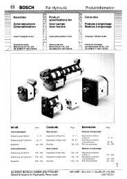
8.7 Load diagram, <strong>PST</strong> 6100.XXX L<br />
. Note: For a general description of load diagrams, see Section 3<br />
1000<br />
900<br />
800<br />
I prim (ED) in A<br />
700<br />
600<br />
500<br />
400<br />
300<br />
200<br />
100<br />
1 10 100<br />
ED in %<br />
primary continuous current, air cooling<br />
calculated primary peak current, air cooling, t s = 0.2s, 1 000 000 spots<br />
Load diagram, <strong>PST</strong> 6100.XXX L<br />
1070 080 058-101 (2001.04) GB
8-8<br />
<strong>PST</strong> 6100.XXX L<br />
8.8 Accessories, <strong>PST</strong> 6100.XXX L<br />
8.8.1 Dimensioned drawing, accessories kit<br />
An accessories kit is available for mounting the inverter with its back on the<br />
mounting plate.<br />
Accessories kit, mounting plate Mounting plate dimensions<br />
tool<br />
1.5 thick<br />
radiuses without dimensions = R2<br />
Dimensions without tolerances<br />
Range of nominal<br />
for angles<br />
(short leg<br />
length)<br />
above<br />
sizes<br />
above<br />
greater<br />
than<br />
up to<br />
to to<br />
to<br />
Dimensioned drawing, accessories kit<br />
1070 080 058-101 (2001.04) GB
<strong>PST</strong> 6100.XXX L 8-9<br />
D<br />
D<br />
For I/O module,<br />
see <strong>Technical</strong> Information, <strong>PST</strong> 6000, Control and I/O Level Description.<br />
For insertable profiles for electric connection, see the section on ordering.<br />
1070 080 058-101 (2001.04) GB
8-10<br />
<strong>PST</strong> 6100.XXX L<br />
8.9 Ordering accessories<br />
Not included in shipment:<br />
Designation<br />
Insertable profile for pin connectors on small wire sizes, line<br />
connection and welding transformer connection<br />
Part no.<br />
1070 918 779<br />
Accessories kit for <strong>PST</strong> 6100.XXX L mounting 1070 078 273<br />
SSR 81.00 current sensor without fixing device,<br />
in the form of a toroid coil;<br />
55 mm internal diameter; with 5-pole sleeve terminal<br />
SSR 81.01-08 current sensor with fixing device;<br />
e.g. for various electrode makes<br />
1070 048 099<br />
on request<br />
Mating connector for SSR 81.0X current sensor 1070 913 489<br />
Sensor cable LiYCY 2x2x0,75 mm 2 shielded 1070 913 494<br />
1070 080 058-101 (2001.04) GB
<strong>PST</strong> 6250.XXX L 9-1<br />
9 <strong>PST</strong> 6250.XXX L<br />
9.1 <strong>PST</strong> 6250.XXX L overview<br />
D <strong>PST</strong> 6250.XXX L :<br />
D <strong>Thyristor</strong> power unit for welding transformers up to max. 250 kVA<br />
D Air cooling<br />
D Integrated control function<br />
D Rated voltage 400 V -20% to 600 V +10%, 50/60 Hz<br />
9.2 Explanation of drawings<br />
The following drawings show the<br />
D front plate with modules of the thyristor power unit<br />
D integrated weld timer<br />
D slot for the parallel, serial or fieldbus I/O interface<br />
D slot prepared for retrofitting a quality module<br />
D slot for fieldbus interface for programming (optional)<br />
D<br />
D<br />
D<br />
D<br />
D<br />
technical data<br />
dimensions and mounting options<br />
mains connection<br />
D connection of the welding transformer<br />
load diagram<br />
accessories and part numbers<br />
. Note: No heat sinks shown on drawings.<br />
1070 080 058-101 (2001.04) GB
9-2<br />
<strong>PST</strong> 6250.XXX L<br />
9.3 <strong>PST</strong> 6250.XXX L front panel<br />
[1]<br />
[1] [1]<br />
[2]<br />
V1<br />
U1<br />
[5]<br />
D - 64711 Erbach 107 Made in Germany<br />
[3]<br />
U1<br />
U2<br />
V1<br />
V2<br />
A<br />
D<br />
D<br />
R<br />
[6] [7]<br />
[8]<br />
[4]<br />
U2<br />
V2<br />
[9]<br />
[1]<br />
[1]<br />
[1]<br />
<strong>PST</strong> 6250.XXX L front panel<br />
[1] M6 mounting options<br />
D rear panel<br />
D left side panel (mounting cutout required)<br />
[2] mains supply connection<br />
[3] thyristor power unit symbol<br />
[4] welding transformer connection<br />
[5] integrated weld timer<br />
[6] slot for type-specific I/O interface:<br />
D parallel I/O interface<br />
D serial I/O interface<br />
D fieldbus I/O interface<br />
1070 080 058-101 (2001.04) GB
<strong>PST</strong> 6250.XXX L 9-3<br />
[7] slot for retrofitting a quality module<br />
[8] slot for fieldbus interface for programming<br />
[9] battery compartment<br />
1070 080 058-101 (2001.04) GB
9-4<br />
<strong>PST</strong> 6250.XXX L<br />
9.4 <strong>Technical</strong> data, <strong>PST</strong> 6250.XXX L<br />
Type<br />
Weld timer<br />
I/O interface<br />
Quality module<br />
Degree of protection<br />
<strong>Thyristor</strong> power unit ambient temperature<br />
Cooling<br />
Temperature monitoring<br />
Storage temperature<br />
Corrosion<br />
2-phase thyristor power unit, module designed<br />
for recessed mounting<br />
integrated<br />
Slot for parallel, serial or fieldbus interface<br />
Slot prepared for retrofitting<br />
IP 20; designed for modular enclosure or<br />
for installation in switchgear cabinets<br />
with IP 54<br />
max. 55° C<br />
air, max. 45° C<br />
integrated<br />
-25° C to +70° C<br />
The ambient air must be free of acids,<br />
caustic solutions, corrosive agents, salts<br />
and metal vapors of any major concentration<br />
Humidity Humidity class F as per DIN 40040;<br />
20° C at 90% relative humidity;<br />
40° C at 50% relative humidity (as per<br />
VDE 0113);<br />
Moisture condensation on the thyristor<br />
power units must be prevented.<br />
Air pressure<br />
Line voltage connection<br />
grounded TN or TT system<br />
Nominal system current;<br />
max. continuous thermal current<br />
Voltage supply;<br />
Weld timer CPU;<br />
I/O interface<br />
Duty cycle (ED)<br />
Clock frequency<br />
Overvoltage protection<br />
Any within a range of up to 2000 m<br />
above sea level<br />
400 V -20% to 600 V +10%;<br />
50/60 Hz<br />
200 A<br />
24 V DC; min. 19 V DC up to max. 30 V<br />
DC as per EN 61131-2, (external power<br />
supply), or, alternatively, power supply<br />
from the weld current system (internal<br />
power supply)<br />
max. 50% duty cycle permitted (regardless<br />
of possible power unit operating currents,<br />
limited by the built-in 2.2 kΩ de-excitation<br />
resistor)<br />
50/60 Hz<br />
MOV; Metal Oxide Varistor<br />
Electrical connection, mains supply<br />
and transformer via box terminal; max. 95 mm 2<br />
Wire range 95 mm 2<br />
Basic switchgear cabinet loss<br />
Weight<br />
Mounting position<br />
70 W<br />
approx. 12.5 kg<br />
vertical or with its back on mounting<br />
plate<br />
1070 080 058-101 (2001.04) GB
<strong>PST</strong> 6250.XXX L 9-5<br />
9.5 Dimensioned drawing, <strong>PST</strong> 6250.XXX L<br />
Side view, right<br />
(as seen from the front)<br />
Front view<br />
Accessories kit<br />
078 273<br />
plate for optional mounting<br />
100 mm min. installation clearance<br />
at top and bottom of<br />
thyristor power unit!<br />
sealing face,<br />
3 mm flat gasket<br />
required<br />
Mounting cut-out recommended for<br />
mounting on left side panel<br />
Plan view<br />
Drawings not true to scale. Dimensions without tolerances: 0.5<br />
Dimensioned drawing, <strong>PST</strong> 6250.XXX L<br />
1070 080 058-101 (2001.04) GB
9-6<br />
<strong>PST</strong> 6250.XXX L<br />
9.6 Electrical connection, <strong>PST</strong> 6250.XXX L<br />
Side view, right<br />
(as seen from the front)<br />
from mains<br />
PE<br />
U1<br />
V1<br />
all terminals<br />
max. 95 mm 2<br />
U2<br />
V2<br />
to welding transformer<br />
Electrical connection, <strong>PST</strong> 6250.XXX L<br />
. Note: For the connections of the various control functions, please see<br />
the respective manuals ”<strong>PST</strong> 6000, Control and I/O Level Description”.<br />
1070 080 058-101 (2001.04) GB
<strong>PST</strong> 6250.XXX L 9-7<br />
9.7 Load diagram, <strong>PST</strong> 6250.XXX L<br />
. Note: For a general description of load diagrams, see Section 3<br />
I prim (ED) in A<br />
3400<br />
3200<br />
3000<br />
2800<br />
2600<br />
2400<br />
2200<br />
2000<br />
1800<br />
1600<br />
1400<br />
1200<br />
1000<br />
800<br />
600<br />
400<br />
200<br />
1 10 100<br />
ED in %<br />
primary continuous current, air cooling<br />
calculated primary peak current, air cooling, t s = 0.2s, 1 000 000 spots<br />
Load diagram, <strong>PST</strong> 6250.XXX L<br />
1070 080 058-101 (2001.04) GB
9-8<br />
<strong>PST</strong> 6250.XXX L<br />
9.8 Accessories, <strong>PST</strong> 6250.XXX L<br />
9.8.1 Dimensioned drawing, accessories kit<br />
An accessories kit is available for mounting the inverter with its back on the<br />
mounting plate.<br />
Accessories kit, mounting plate Mounting plate dimensions<br />
tool<br />
1.5 thick<br />
radiuses without dimensions = R2<br />
Dimensions without tolerances<br />
Range of nominal<br />
for angles<br />
(short leg<br />
length)<br />
above<br />
sizes<br />
above<br />
greater<br />
than<br />
up to<br />
to to<br />
to<br />
Dimensioned drawing, accessories kit<br />
1070 080 058-101 (2001.04) GB
<strong>PST</strong> 6250.XXX L 9-9<br />
D<br />
D<br />
For I/O module,<br />
see <strong>Technical</strong> Information, <strong>PST</strong> 6000, Control and I/O Level Description.<br />
For insertable profiles for electric connection, see the section on ordering.<br />
1070 080 058-101 (2001.04) GB
9-10<br />
<strong>PST</strong> 6250.XXX L<br />
9.9 Ordering accessories<br />
Not included in shipment:<br />
Designation<br />
Insertable profile for pin connectors on small wire sizes, line<br />
connection and welding transformer connection<br />
Part no.<br />
1070 918 466<br />
Accessories kit for <strong>PST</strong> 6250.XXX L mounting 1070 078 273<br />
SSR 81.00 current sensor without fixing device,<br />
in the form of a toroid coil;<br />
55 mm internal diameter; with 5-pole sleeve terminal<br />
SSR 81.01-08 current sensor with fixing device;<br />
e.g. for various electrode makes<br />
1070 048 099<br />
on request<br />
Mating connector for SSR 81.0X current sensor 1070 913 489<br />
Sensor cable LiYCY 2x2x0,75 mm 2 shielded 1070 913 494<br />
1070 080 058-101 (2001.04) GB
CE declaration of conformity 10-1<br />
10 CE declaration of conformity<br />
1070 080 058-101 (2001.04) GB
10-2<br />
CE declaration of conformity<br />
Notes:<br />
1070 080 058-101 (2001.04) GB
Annex A-1<br />
A<br />
Annex<br />
A.1 Index<br />
Symbols<br />
”Ready” LED, 6-1<br />
”Ready” message, 6-1<br />
A<br />
Accessories kit, 8-10, 9-10<br />
Accessories, <strong>PST</strong> 6100.XXX L, 8-8<br />
Accessories, <strong>PST</strong> 6250.XXX L, 9-8<br />
Air pressure, 8-4, 9-4<br />
Ambient temperature, 3-1, 8-4, 9-4<br />
Assembly, 1-6<br />
B<br />
Basic switchgear cabinet loss, 8-4, 9-4<br />
Battery, 5-1<br />
Battery compartment, 8-3, 9-3<br />
Block diagram of a thyristor power unit, 2-3<br />
C<br />
Cables, 1-10<br />
CE declaration of conformity, 10-1<br />
Clock frequency, 8-4, 9-4<br />
Commissioning, 4-1<br />
Components, 2-2<br />
Connection<br />
U1, 1-11<br />
U2, 1-11<br />
V1, 1-11<br />
V2, 1-11<br />
Welding transformer, 1-11<br />
Cooling, 8-4, 9-4<br />
Cooling water, 1-8<br />
Chlorides, 1-8<br />
Degree of hardness, 1-8<br />
Insoluble substances, 1-8<br />
Nitrates, 1-8<br />
pH value, 1-8<br />
Sulfates, 1-8<br />
Corrosion, 8-4, 9-4<br />
Current sensor, 8-10, 9-10<br />
D<br />
Degree of protection, 8-4, 9-4<br />
Dimensioned drawing, accessories kit, 8-8, 9-8<br />
Dimensioned drawing, <strong>PST</strong> 6100.XXX L, 8-5<br />
Dimensioned drawing, <strong>PST</strong> 6250.XXX L, 9-5<br />
Duty cycle, 3-1, 8-4, 9-4<br />
E<br />
ED duty cycle, 3-1<br />
Electrical connection, 1-9, 8-4, 9-4<br />
Electrical connection, <strong>PST</strong> 6100.XXX L, 8-6<br />
Electrical connection, <strong>PST</strong> 6250.XXX L, 9-6<br />
EMC, 1-12<br />
EMERGENCY-STOP facilities, 1-15, 5-1<br />
F<br />
Features, 2-1, 7-1<br />
Field bus module, 2-2<br />
Fieldbus interface for programming, 8-1, 9-1<br />
Function, 2-4<br />
1070 080 058-101 (2001.04) GB
A-2<br />
Annex<br />
H<br />
Humidity, 8-4, 9-4<br />
I<br />
I/O interface, 2-2, 8-1, 8-4, 9-1, 9-4<br />
I/O module, 8-9, 9-9<br />
Insertable profile, 8-10, 9-10<br />
Installation, 1-6<br />
Integrated weld timer, 8-1, 9-1<br />
Intended use, 1-3<br />
L<br />
Line voltage connection, 8-4, 9-4<br />
Load capability, 3-1<br />
Load diagram, 3-1<br />
Load diagram, <strong>PST</strong> 6100.XXX L, 8-7<br />
Load diagram, <strong>PST</strong> 6250.XXX L, 9-7<br />
M<br />
Mains supply, 8-4, 9-4<br />
Maintenance, 1-15, 5-1<br />
Malfunction, 6-1<br />
Malfunctions, 6-1<br />
Maximum welding current, 1-13, 3-1<br />
Modifications, 1-2<br />
Modifications by the user, 1-14<br />
Modules, 2-2<br />
Monitoring, 2-4<br />
Monitoring functions, 2-4<br />
Mounting, 1-6<br />
Mounting position, 8-4, 9-4<br />
N<br />
Nominal system current, 8-4, 9-4<br />
Notes on rating, 3-1<br />
O<br />
Operation, 1-13<br />
Ordering accessories, 8-10, 9-10<br />
Output currents, 3-1<br />
Overall weld cycle duration, 3-1<br />
Overload, 2-4<br />
Overvoltage protection, 8-4, 9-4<br />
P<br />
Pacemaker, 1-4<br />
PE connection, 1-11<br />
<strong>PST</strong> 6100.XXX L, 8-1<br />
<strong>PST</strong> 6100.XXX L front panel, 8-2<br />
<strong>PST</strong> 6100.XXX L overview, 8-1<br />
<strong>PST</strong> 6250.XXX L, 9-1<br />
<strong>PST</strong> 6250.XXX L front panel, 9-2<br />
<strong>PST</strong> 6250.XXX L overview, 9-1<br />
Q<br />
Qualified personnel, 1-5<br />
Quality module, 2-2, 8-1, 8-4, 9-1, 9-4<br />
R<br />
Repair, 1-15, 5-1<br />
Replacement parts, 5-1<br />
Retrofits, 1-14<br />
S<br />
Safety instructions, 1-1, 1-2<br />
Sensor cable, 8-10, 9-10<br />
Setup, 2-1<br />
Spare parts, 1-15, 5-1<br />
Storage temperature, 8-4, 9-4<br />
Symbols, 1-2<br />
T<br />
<strong>Technical</strong> data, <strong>PST</strong> 6100.XXX L, 8-4<br />
<strong>Technical</strong> data, <strong>PST</strong> 6250.XXX L, 9-4<br />
Temperature monitoring, 8-4, 9-4<br />
Test procedures, 1-15, 5-1<br />
Thermal detector, 6-1<br />
1070 080 058-101 (2001.04) GB
Annex A-3<br />
<strong>Thyristor</strong> load, 3-1<br />
<strong>Thyristor</strong> unit temperature, 6-1<br />
Training courses, 1-5<br />
Type, 8-4, 9-4<br />
Type overview, 7-1<br />
V<br />
Voltage supply, 8-4, 9-4<br />
W<br />
Weight, 8-4, 9-4<br />
Weld time, 3-1<br />
Weld timer, 2-2, 8-4, 9-4<br />
Welding current, maximum, 1-13<br />
Welding splashes, 1-16<br />
Wire range, 8-4, 9-4<br />
Working safely, 1-16<br />
1070 080 058-101 (2001.04) GB
A-4<br />
Annex<br />
1070 080 058-101 (2001.04) GB
A-1<br />
1070 080 058-101 (2001.04) GB · TI WS· AT/VWS · Printed in Germany<br />
1070 080 058-101 (2001.04) GB