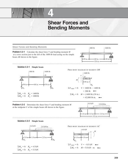
Shear Forces and Bending Moments
Shear Forces and Bending Moments
Shear Forces and Bending Moments

Create successful ePaper yourself
Turn your PDF publications into a flip-book with our unique Google optimized e-Paper software.
4<br />
<strong>Shear</strong> <strong>Forces</strong> <strong>and</strong><br />
<strong>Bending</strong> <strong>Moments</strong><br />
<strong>Shear</strong> <strong>Forces</strong> <strong>and</strong> <strong>Bending</strong> <strong>Moments</strong><br />
800 lb<br />
1600 lb<br />
Problem 4.3-1 Calculate the shear force V <strong>and</strong> bending moment M<br />
at a cross section just to the left of the 1600-lb load acting on the simple<br />
beam AB shown in the figure.<br />
A<br />
30 in. 60 in. 30 in.<br />
120 in.<br />
B<br />
B<br />
R B<br />
Solution 4.3-1 Simple beam<br />
Free-body diagram of segment DB<br />
800 lb<br />
1600 lb<br />
1600 lb<br />
A<br />
D<br />
V<br />
B<br />
M<br />
D<br />
R A ©F VERT 0:V 1600 lb 1400 lb<br />
30 in.<br />
30 in. 60 in. 30 in.<br />
R B<br />
200 lb<br />
M A<br />
0: R B<br />
1400 lb<br />
©M D 0:M (1400 lb)(30 in.)<br />
M B<br />
0: R A<br />
1000 lb<br />
42,000 lb-in.<br />
Problem 4.3-2 Determine the shear force V <strong>and</strong> bending moment M<br />
at the midpoint C of the simple beam AB shown in the figure.<br />
A<br />
6.0 kN<br />
C<br />
2.0 kN/m<br />
B<br />
1.0 m 1.0 m<br />
4.0 m<br />
2.0 m<br />
Solution 4.3-2<br />
Simple beam<br />
A<br />
6.0 kN<br />
C<br />
2.0 kN/m<br />
1.0 m 1.0 m 2.0 m<br />
R A<br />
B<br />
R B<br />
Free-body diagram of segment AC<br />
6.0 kN<br />
A<br />
C<br />
V M<br />
1.0 m 1.0 m<br />
R A<br />
M A<br />
0:<br />
M B<br />
0:<br />
R B<br />
4.5 kN<br />
R A<br />
5.5 kN<br />
©F VERT 0:V 0.5 kN<br />
©M C 0:M 5.0 kN m<br />
259
260 CHAPTER 4 <strong>Shear</strong> <strong>Forces</strong> <strong>and</strong> <strong>Bending</strong> <strong>Moments</strong><br />
Problem 4.3-3 Determine the shear force V <strong>and</strong> bending moment M at<br />
the midpoint of the beam with overhangs (see figure). Note that one load<br />
acts downward <strong>and</strong> the other upward.<br />
P<br />
P<br />
b<br />
L<br />
b<br />
Solution 4.3-3<br />
Beam with overhangs<br />
P<br />
©M B 0<br />
b<br />
A<br />
R A 1 [P(L b b)]<br />
L<br />
P<br />
L<br />
b<br />
R A RB<br />
P ¢1 2b L ≤(upward)<br />
B<br />
P<br />
©M A 0:R B P ¢1 2b L ≤(downward)<br />
Free-body diagram (C is the midpoint)<br />
©F VERT 0:<br />
V R A P P ¢1 2b L ≤ P<br />
©M C 0:<br />
M<br />
A<br />
C<br />
b L/2<br />
R A V<br />
M P ¢1 2b L ≤ ¢L 2 ≤ P ¢b L 2 ≤<br />
M PL<br />
PL<br />
Pb Pb <br />
2 2 0<br />
2bP<br />
L<br />
Problem 4.3-4 Calculate the shear force V <strong>and</strong> bending moment M at a<br />
cross section located 0.5 m from the fixed support of the cantilever beam<br />
AB shown in the figure.<br />
A<br />
4.0 kN<br />
1.5 kN/m<br />
B<br />
1.0 m 1.0 m 2.0 m<br />
Solution 4.3-4<br />
A<br />
Cantilever beam<br />
4.0 kN<br />
1.5 kN/m<br />
1.0 m 1.0 m 2.0 m<br />
Free-body diagram of segment DB<br />
Point D is 0.5 m from support A.<br />
B<br />
©F VERT 0:<br />
V 4.0 kN (1.5 kNm)(2.0 m)<br />
4.0 kN 3.0 kN 7.0 kN<br />
©M D 0:M (4.0 kN)(0.5 m)<br />
(1.5 kNm)(2.0 m)(2.5 m)<br />
2.0 kN m 7.5 kN m<br />
9.5 kN m<br />
M<br />
V<br />
D<br />
4.0 kN<br />
1.5 kN/m<br />
B<br />
0.5 m<br />
1.0 m<br />
2.0 m
SECTION 4.3 <strong>Shear</strong> <strong>Forces</strong> <strong>and</strong> <strong>Bending</strong> <strong>Moments</strong> 261<br />
Problem 4.3-5 Determine the shear force V <strong>and</strong> bending moment M<br />
at a cross section located 16 ft from the left-h<strong>and</strong> end A of the beam<br />
with an overhang shown in the figure.<br />
A<br />
400 lb/ft 200 lb/ft<br />
B<br />
C<br />
10 ft 10 ft<br />
6 ft<br />
6 ft<br />
Solution 4.3-5<br />
A<br />
Beam with an overhang<br />
400 lb/ft 200 lb/ft<br />
B<br />
C<br />
A<br />
10 ft 10 ft 6 ft 6 ft<br />
R A R B<br />
Free-body diagram of segment AD<br />
400 lb/ft<br />
R A<br />
10 ft<br />
6 ft<br />
D<br />
V<br />
M<br />
M B<br />
0:<br />
M A<br />
0:<br />
R A<br />
2460 lb<br />
R B<br />
2740 lb<br />
Point D is 16 ft from support A.<br />
©F VERT 0:<br />
V 2460 lb (400 lbft)(10 ft)<br />
1540 lb<br />
©M D 0:M (2460 lb)(16 ft)<br />
(400 lbft)(10 ft)(11 ft)<br />
4640 lb-ft<br />
Problem 4.3-6 The beam ABC shown in the figure is simply<br />
supported at A <strong>and</strong> B <strong>and</strong> has an overhang from B to C. The<br />
loads consist of a horizontal force P 1<br />
4.0 kN acting at the<br />
end of a vertical arm <strong>and</strong> a vertical force P 2<br />
8.0 kN acting at<br />
the end of the overhang.<br />
Determine the shear force V <strong>and</strong> bending moment M at<br />
a cross section located 3.0 m from the left-h<strong>and</strong> support.<br />
(Note: Disregard the widths of the beam <strong>and</strong> vertical arm <strong>and</strong><br />
use centerline dimensions when making calculations.)<br />
P 1 = 4.0 kN<br />
1.0 m<br />
A<br />
P 2 = 8.0 kN<br />
B<br />
C<br />
4.0 m 1.0 m<br />
Solution 4.3-6 Beam with vertical arm<br />
P 1 = 4.0 kN<br />
P 2 = 8.0 kN<br />
1.0 m<br />
A<br />
B<br />
4.0 m 1.0 m<br />
R A<br />
R B<br />
M B<br />
0: R A<br />
1.0 kN (downward)<br />
M A<br />
0: R B<br />
9.0 kN (upward)<br />
Free-body diagram of segment AD<br />
Point D is 3.0 m from support A.<br />
A<br />
D<br />
M<br />
4.0 kN • m<br />
3.0 m<br />
R A<br />
V<br />
©F VERT 0:V R A 1.0 kN<br />
©M D 0:M R A (3.0 m) 4.0 kN m<br />
7.0 kN m
262 CHAPTER 4 <strong>Shear</strong> <strong>Forces</strong> <strong>and</strong> <strong>Bending</strong> <strong>Moments</strong><br />
Problem 4.3-7 The beam ABCD shown in the figure has overhangs<br />
at each end <strong>and</strong> carries a uniform load of intensity q.<br />
For what ratio b/L will the bending moment at the midpoint of the<br />
beam be zero?<br />
A<br />
B<br />
q<br />
C<br />
D<br />
b<br />
L<br />
b<br />
Solution 4.3-7 Beam with overhangs<br />
q<br />
Free-body diagram of left-h<strong>and</strong> half of beam:<br />
Point E is at the midpoint of the beam.<br />
A<br />
D<br />
B C<br />
q<br />
b<br />
L<br />
b<br />
R B R A<br />
M = 0 (Given)<br />
C E<br />
b L/2 V<br />
From symmetry <strong>and</strong> equilibrium of vertical forces:<br />
R B<br />
R B R C q ¢b L 2 ≤<br />
©M E 0 <br />
R B ¢ L 2 ≤ q ¢1 2 ≤ ¢b L 2 ≤ 2<br />
0<br />
q ¢b L 2 ≤ ¢L 2 ≤ q ¢1 2 ≤ ¢b L 2 ≤ 2<br />
0<br />
Solve for b/L :<br />
b<br />
L 1 2<br />
Problem 4.3-8 At full draw, an archer applies a pull of 130 N to the<br />
bowstring of the bow shown in the figure. Determine the bending moment<br />
at the midpoint of the bow.<br />
70°<br />
1400 mm<br />
350 mm
SECTION 4.3 <strong>Shear</strong> <strong>Forces</strong> <strong>and</strong> <strong>Bending</strong> <strong>Moments</strong> 263<br />
Solution 4.3-8<br />
Archer’s bow<br />
B<br />
Free-body diagram of segment BC<br />
B<br />
<br />
P<br />
A<br />
<br />
C<br />
H<br />
T<br />
H<br />
2<br />
b<br />
C<br />
M<br />
©M C 0 <br />
b<br />
P 130 N<br />
70°<br />
H 1400 mm<br />
1.4 m<br />
b 350 mm<br />
0.35 m<br />
Free-body diagram of point A<br />
T(cos H b)¢ ≤ T(sin b)(b) M 0<br />
2<br />
M T H ¢ cosb b sin b≤<br />
2<br />
P 2 ¢H b tan b≤<br />
2<br />
Substitute numerical values:<br />
M 130 N B 1.4 m (0.35 m)(tan 70)R<br />
2 2<br />
M 108 N m<br />
T<br />
<br />
P<br />
A<br />
T<br />
T tensile force in the bowstring<br />
F HORIZ<br />
0: 2T cos P 0<br />
T <br />
P<br />
2 cos b
264 CHAPTER 4 <strong>Shear</strong> <strong>Forces</strong> <strong>and</strong> <strong>Bending</strong> <strong>Moments</strong><br />
Problem 4.3-9 A curved bar ABC is subjected to loads in the form<br />
of two equal <strong>and</strong> opposite forces P, as shown in the figure. The axis of<br />
the bar forms a semicircle of radius r.<br />
Determine the axial force N, shear force V, <strong>and</strong> bending moment M<br />
acting at a cross section defined by the angle .<br />
P<br />
A<br />
B<br />
<br />
O<br />
r<br />
C<br />
P<br />
P<br />
A<br />
M<br />
<br />
V<br />
N<br />
Solution 4.3-9<br />
Curved bar<br />
P<br />
A<br />
B<br />
<br />
O<br />
r<br />
C<br />
P<br />
P<br />
P cos <br />
P sin <br />
A<br />
B<br />
M<br />
<br />
V<br />
N<br />
O<br />
©F N 0 Q b N P sin u 0<br />
N P sin u<br />
F V 0<br />
<br />
R a V P cos u 0<br />
V P cos u<br />
©M O 0 M Nr 0<br />
M Nr Pr sin u<br />
Problem 4.3-10 Under cruising conditions the distributed load<br />
acting on the wing of a small airplane has the idealized variation<br />
shown in the figure.<br />
Calculate the shear force V <strong>and</strong> bending moment M at the<br />
inboard end of the wing.<br />
1600 N/m<br />
900 N/m<br />
2.6 m<br />
2.6 m<br />
1.0 m<br />
Solution 4.3-10 Airplane wing<br />
1600 N/m<br />
900 N/m<br />
M<br />
V<br />
A<br />
2.6 m<br />
2.6 m<br />
1.0 m<br />
B<br />
Loading (in three parts)<br />
700 N/m 1<br />
900 N/m<br />
2<br />
A<br />
3<br />
B<br />
<strong>Shear</strong> Force<br />
F VERT<br />
0 c T <br />
<strong>Bending</strong><br />
V 1 (700 Nm)(2.6 m) (900 Nm)(5.2 m)<br />
2<br />
1 (900 Nm)(1.0 m) 0<br />
2<br />
V 6040 N 6.04 kN<br />
(Minus means the shear force acts opposite to the<br />
direction shown in the figure.)<br />
Moment<br />
©M A 0 <br />
M 1 2<br />
(900 Nm)(5.2 m)(2.6 m)<br />
1 2<br />
m<br />
(700 Nm)(2.6 m)¢2.6 ≤<br />
3<br />
1.0 m<br />
(900 Nm)(1.0 m)¢5.2 m ≤ 0<br />
3<br />
M 788.67 N • m 12,168 N • m 2490 N • m<br />
15,450 N • m<br />
15.45 kN m
SECTION 4.3 <strong>Shear</strong> <strong>Forces</strong> <strong>and</strong> <strong>Bending</strong> <strong>Moments</strong> 265<br />
Problem 4.3-11 A beam ABCD with a vertical arm CE is supported as<br />
a simple beam at A <strong>and</strong> D (see figure). A cable passes over a small pulley<br />
that is attached to the arm at E. One end of the cable is attached to the<br />
beam at point B.<br />
What is the force P in the cable if the bending moment in the<br />
beam just to the left of point C is equal numerically to 640 lb-ft?<br />
(Note: Disregard the widths of the beam <strong>and</strong> vertical arm <strong>and</strong> use<br />
centerline dimensions when making calculations.)<br />
A<br />
B<br />
Cable<br />
C<br />
E<br />
D<br />
8 ft<br />
P<br />
6 ft 6 ft 6 ft<br />
Solution 4.3-11<br />
Beam with a cable<br />
E<br />
P<br />
Free-body diagram of section AC<br />
P<br />
P<br />
__ 4P<br />
9<br />
A<br />
B<br />
Cable<br />
C<br />
6 ft 6 ft 6 ft<br />
8 ft<br />
D<br />
__ 4P<br />
9<br />
P<br />
__ 4P<br />
9<br />
A<br />
©M C 0 <br />
4P __<br />
5<br />
__ 3P<br />
5<br />
6 ft B 6 ft<br />
C<br />
V<br />
M<br />
N<br />
UNITS:<br />
P in lb<br />
M in lb-ft<br />
M 4P 5 (6 ft) 4P 9<br />
(12 ft) 0<br />
M 8P<br />
15 lb-ft<br />
Numerical value of M equals 640 lb-ft.<br />
∴ 640 lb-ft 8P<br />
15 lb-ft<br />
<strong>and</strong> P 1200 lb<br />
Problem 4.3-12 A simply supported beam AB supports a trapezoidally<br />
distributed load (see figure). The intensity of the load varies linearly<br />
from 50 kN/m at support A to 30 kN/m at support B.<br />
Calculate the shear force V <strong>and</strong> bending moment M at the midpoint<br />
of the beam.<br />
50 kN/m<br />
A<br />
30 kN/m<br />
B<br />
3 m
266 CHAPTER 4 <strong>Shear</strong> <strong>Forces</strong> <strong>and</strong> <strong>Bending</strong> <strong>Moments</strong><br />
Solution 4.3-12 Beam with trapezoidal load<br />
50 kN/m<br />
Free-body diagram of section CB<br />
30 kN/m<br />
Point C is at the midpoint of the beam.<br />
40 kN/m<br />
A<br />
B<br />
30 kN/m<br />
V<br />
3 m<br />
M<br />
C<br />
B<br />
R A RB<br />
1.5 m<br />
55 kN<br />
Reactions<br />
©M B 0 R A (3 m) (30 kNm)(3 m)(1.5 m)<br />
(20 kNm)(3 m)( 1 2 )(2 m) 0<br />
R A<br />
65 kN<br />
©F VERT 0 c<br />
R A R B 1 2 (50 kNm 30 kNm)(3 m) 0<br />
R B<br />
55 kN<br />
F VERT<br />
0 c <br />
T <br />
V (30 kNm)(1.5 m) 1 2(10 kNm)(1.5 m)<br />
55 kN 0<br />
V 2.5 kN<br />
©M C 0 <br />
M (30 kN/m)(1.5 m)(0.75 m)<br />
1 2 (10 kNm)(1.5 m)(0.5 m)<br />
(55 kN)(1.5 m) 0<br />
M 45.0 kN m<br />
Problem 4.3-13 Beam ABCD represents a reinforced-concrete<br />
foundation beam that supports a uniform load of intensity q 1<br />
3500 lb/ft<br />
(see figure). Assume that the soil pressure on the underside of the beam is<br />
uniformly distributed with intensity q 2<br />
.<br />
(a) Find the shear force V B<br />
<strong>and</strong> bending moment M B<br />
at point B.<br />
(b) Find the shear force V m<br />
<strong>and</strong> bending moment M m<br />
at the midpoint<br />
of the beam.<br />
A<br />
q 1 = 3500 lb/ft<br />
B<br />
C<br />
q 2<br />
3.0 ft 8.0 ft 3.0 ft<br />
D<br />
Solution 4.3-13 Foundation beam<br />
q 1 = 3500 lb/ft<br />
(b) V <strong>and</strong> M at midpoint E<br />
A B C D<br />
3500 lb/ft<br />
A<br />
B<br />
M B M E<br />
0:<br />
F VERT<br />
0:<br />
M m<br />
(2000 lb/ft)(7 ft)(3.5 ft)<br />
2000 lb/ft V B<br />
3 ft<br />
V B 6000 lb<br />
(3500 lb/ft)(4 ft)(2 ft)<br />
A B E M m<br />
q 2<br />
3.0 ft 8.0 ft 3.0 ft<br />
2000 lb/ft<br />
V m<br />
F VERT<br />
0: q 2<br />
(14 ft) q 1<br />
(8 ft)<br />
3 ft<br />
4 ft<br />
∴ q 2 8 14 q 1 2000 lbft<br />
F VERT<br />
0: V m<br />
(2000 lb/ft)(7 ft) (3500 lb/ft)(4 ft)<br />
(a) V <strong>and</strong> M at point B<br />
V m 0<br />
©M B 0:M B 9000 lb-ft<br />
M m 21,000 lb-ft
SECTION 4.3 <strong>Shear</strong> <strong>Forces</strong> <strong>and</strong> <strong>Bending</strong> <strong>Moments</strong> 267<br />
Problem 4.3-14 The simply-supported beam ABCD is loaded by<br />
a weight W 27 kN through the arrangement shown in the figure.<br />
The cable passes over a small frictionless pulley at B <strong>and</strong> is attached<br />
at E to the end of the vertical arm.<br />
Calculate the axial force N, shear force V, <strong>and</strong> bending moment<br />
M at section C, which is just to the left of the vertical arm.<br />
(Note: Disregard the widths of the beam <strong>and</strong> vertical arm <strong>and</strong> use<br />
centerline dimensions when making calculations.)<br />
A<br />
E<br />
Cable<br />
1.5 m<br />
B C<br />
2.0 m 2.0 m 2.0 m<br />
D<br />
W = 27 kN<br />
Solution 4.3-14<br />
Beam with cable <strong>and</strong> weight<br />
E<br />
Free-body diagram of pulley at B<br />
Cable<br />
1.5 m<br />
27 kN<br />
A<br />
B C<br />
D<br />
21.6 kN<br />
2.0 m 2.0 m 2.0 m<br />
10.8 kN<br />
27 kN<br />
27 kN<br />
R A R D<br />
R A<br />
18 kN<br />
R D<br />
9kN<br />
Free-body diagram of segment ABC of beam<br />
10.8 kN<br />
21.6 kN<br />
A<br />
B<br />
C<br />
2.0 m 2.0 m<br />
V<br />
18 kN<br />
©F HORIZ 0:N 21.6 kN (compression)<br />
©F VERT 0:V 7.2 kN<br />
©M C 0:M 50.4 kN m<br />
M<br />
N
268 CHAPTER 4 <strong>Shear</strong> <strong>Forces</strong> <strong>and</strong> <strong>Bending</strong> <strong>Moments</strong><br />
Problem 4.3-15 The centrifuge shown in the figure rotates in a horizontal<br />
plane (the xy plane) on a smooth surface about the z axis (which is vertical)<br />
with an angular acceleration . Each of the two arms has weight w per unit<br />
length <strong>and</strong> supports a weight W 2.0 wL at its end.<br />
Derive formulas for the maximum shear force <strong>and</strong> maximum bending<br />
moment in the arms, assuming b L/9 <strong>and</strong> c L/10.<br />
y<br />
b L c<br />
W<br />
x<br />
W<br />
<br />
Solution 4.3-15<br />
Rotating centrifuge<br />
L<br />
b c<br />
W<br />
g<br />
__ (L + b + c)<br />
x<br />
wx __<br />
g<br />
Tangential acceleration r<br />
Substitute numerical data:<br />
W<br />
Inertial force Mr <br />
g r<br />
Maximum V <strong>and</strong> M occur at x b.<br />
V max W g (L b c) Lb w<br />
g x dx<br />
W<br />
g<br />
(L b c)<br />
wL (L 2b)<br />
2g<br />
M max W (L b c)(L c)<br />
g<br />
Lb<br />
w<br />
x(x b)dx<br />
g<br />
b<br />
W (L b c)(L c)<br />
g<br />
w L2 <br />
(2L 3b)<br />
6g<br />
b<br />
W 2.0 wLb L 9<br />
91wL 2 <br />
V max <br />
30g<br />
M max <br />
229wL 3 <br />
75g<br />
c L 10
SECTION 4.5 <strong>Shear</strong>-Force <strong>and</strong> <strong>Bending</strong>-Moment Diagrams 269<br />
<strong>Shear</strong>-Force <strong>and</strong> <strong>Bending</strong>-Moment Diagrams<br />
When solving the problems for Section 4.5, draw the shear-force <strong>and</strong><br />
bending-moment diagrams approximately to scale <strong>and</strong> label all critical<br />
ordinates, including the maximum <strong>and</strong> minimum values.<br />
Probs. 4.5-1 through 4.5-10 are symbolic problems <strong>and</strong> Probs. 4.5-11<br />
through 4.5-24 are numerical problems. The remaining problems (4.5-25<br />
through 4.5-30) involve specialized topics, such as optimization, beams<br />
with hinges, <strong>and</strong> moving loads.<br />
Problem 4.5-1 Draw the shear-force <strong>and</strong> bending-moment diagrams for<br />
a simple beam AB supporting two equal concentrated loads P (see figure).<br />
A<br />
a<br />
P<br />
P<br />
a<br />
B<br />
L<br />
Solution 4.5-1<br />
Simple beam<br />
a<br />
P<br />
P<br />
a<br />
A<br />
B<br />
R A = P<br />
L<br />
R B = P<br />
V<br />
0<br />
P<br />
P<br />
Pa<br />
M<br />
0
270 CHAPTER 4 <strong>Shear</strong> <strong>Forces</strong> <strong>and</strong> <strong>Bending</strong> <strong>Moments</strong><br />
Problem 4.5-2 A simple beam AB is subjected to a counterclockwise<br />
couple of moment M 0<br />
acting at distance a from the left-h<strong>and</strong> support<br />
(see figure).<br />
Draw the shear-force <strong>and</strong> bending-moment diagrams for this beam.<br />
A<br />
a<br />
L<br />
M 0<br />
B<br />
Solution 4.5-2<br />
Simple beam<br />
A<br />
B<br />
R A = M 0<br />
L<br />
a<br />
L<br />
R B = M 0<br />
L<br />
V<br />
0<br />
M 0<br />
M 0<br />
L<br />
M<br />
0<br />
M 0 (1 a L )<br />
M 0 a<br />
L<br />
Problem 4.5-3 Draw the shear-force <strong>and</strong> bending-moment diagrams<br />
for a cantilever beam AB carrying a uniform load of intensity q over<br />
one-half of its length (see figure).<br />
A<br />
q<br />
L<br />
— 2<br />
L —2<br />
B<br />
Solution 4.5-3<br />
Cantilever beam<br />
M A = 3qL2<br />
8<br />
A<br />
q<br />
B<br />
R A = qL<br />
2<br />
L<br />
— 2<br />
L —2<br />
qL —2<br />
V<br />
0<br />
M<br />
0<br />
<br />
3qL 2<br />
8<br />
qL<br />
<br />
2<br />
8
SECTION 4.5 <strong>Shear</strong>-Force <strong>and</strong> <strong>Bending</strong>-Moment Diagrams 271<br />
Problem 4.5-4 The cantilever beam AB shown in the figure<br />
is subjected to a concentrated load P at the midpoint <strong>and</strong> a<br />
counterclockwise couple of moment M 1<br />
PL/4 at the free end.<br />
Draw the shear-force <strong>and</strong> bending-moment diagrams for<br />
this beam.<br />
A<br />
P<br />
M 1 = —–<br />
PL<br />
4<br />
B<br />
—<br />
L<br />
—2<br />
L<br />
2<br />
Solution 4.5-4<br />
Cantilever beam<br />
P<br />
M A<br />
A<br />
B<br />
M 1 PL 4<br />
R A P<br />
R A<br />
L/2 L/2<br />
M A PL<br />
4<br />
V<br />
M<br />
0<br />
0<br />
P<br />
PL<br />
4<br />
PL 4<br />
Problem 4.5-5 The simple beam AB shown in the figure is subjected to<br />
a concentrated load P <strong>and</strong> a clockwise couple M 1<br />
PL/4 acting at the<br />
third points.<br />
Draw the shear-force <strong>and</strong> bending-moment diagrams for this beam.<br />
A<br />
P<br />
M 1 = PL —–<br />
4<br />
L<br />
— 3<br />
L —3<br />
L —3<br />
B<br />
Solution 4.5-5<br />
Simple beam<br />
A<br />
P<br />
M 1 = PL —–<br />
4<br />
B<br />
R A = 5P —–<br />
12<br />
L<br />
— 3<br />
L —3<br />
L —3<br />
R B = 7P —–<br />
12<br />
V<br />
0<br />
5P/12<br />
7P/12<br />
5PL/36<br />
7PL/36<br />
M<br />
0<br />
PL/18
272 CHAPTER 4 <strong>Shear</strong> <strong>Forces</strong> <strong>and</strong> <strong>Bending</strong> <strong>Moments</strong><br />
Problem 4.5-6 A simple beam AB subjected to clockwise couples M 1<br />
<strong>and</strong> 2M 1<br />
acting at the third points is shown in the figure.<br />
Draw the shear-force <strong>and</strong> bending-moment diagrams for this beam.<br />
A<br />
M 1 2M 1<br />
B<br />
L<br />
— 3<br />
L —3<br />
L —3<br />
Solution 4.5-6<br />
Simple beam<br />
M 1 2M 1<br />
A<br />
B<br />
R A = 3M —– 1<br />
L<br />
—<br />
L —3<br />
L —3<br />
L<br />
R 3 B = 3M —– 1<br />
L<br />
0<br />
V 3M —– 1<br />
L<br />
M 0 M 1<br />
M 1 M 1<br />
Problem 4.5-7 A simply supported beam ABC is loaded by a vertical<br />
load P acting at the end of a bracket BDE (see figure).<br />
Draw the shear-force <strong>and</strong> bending-moment diagrams for beam ABC.<br />
A<br />
B<br />
D<br />
E<br />
C<br />
P<br />
—<br />
L —4<br />
L —2<br />
L<br />
4<br />
L<br />
Solution 4.5-7<br />
Beam with bracket<br />
A<br />
P<br />
B<br />
PL<br />
—–<br />
4<br />
C<br />
R A = P —–<br />
2<br />
—<br />
L<br />
3L<br />
— 4 4<br />
R C = P —–<br />
2<br />
V<br />
0<br />
P<br />
—–<br />
2<br />
—–<br />
P<br />
<br />
2<br />
M<br />
0<br />
PL<br />
—–<br />
8<br />
3PL<br />
—–<br />
8
SECTION 4.5 <strong>Shear</strong>-Force <strong>and</strong> <strong>Bending</strong>-Moment Diagrams 273<br />
Problem 4.5-8 A beam ABC is simply supported at A <strong>and</strong> B <strong>and</strong><br />
has an overhang BC (see figure). The beam is loaded by two forces<br />
P <strong>and</strong> a clockwise couple of moment Pa that act through the<br />
arrangement shown.<br />
Draw the shear-force <strong>and</strong> bending-moment diagrams for<br />
beam ABC.<br />
A<br />
P P Pa<br />
C<br />
B<br />
a a a a<br />
Solution 4.5-8<br />
Beam with overhang<br />
upper<br />
beam:<br />
P<br />
P<br />
C<br />
a a a<br />
Pa<br />
P<br />
P<br />
lower<br />
beam:<br />
P<br />
B<br />
a a a<br />
P<br />
C<br />
2P<br />
V 0<br />
P<br />
P<br />
M 0<br />
Pa<br />
Problem 4.5-9 Beam ABCD is simply supported at B <strong>and</strong> C <strong>and</strong> has<br />
overhangs at each end (see figure). The span length is L <strong>and</strong> each<br />
overhang has length L/3. A uniform load of intensity q acts along the<br />
entire length of the beam.<br />
Draw the shear-force <strong>and</strong> bending-moment diagrams for this beam.<br />
A<br />
L<br />
3<br />
B<br />
q<br />
L<br />
C<br />
L<br />
3<br />
D<br />
Solution 4.5-9<br />
Beam with overhangs<br />
q<br />
A<br />
L/3<br />
B<br />
L<br />
C<br />
L/3<br />
__ 5qL<br />
R B = __ 5qL<br />
R 6<br />
C = 6<br />
__ qL<br />
qL/3<br />
V 0<br />
2<br />
__ qL<br />
– __ qL<br />
– 3 __ 5qL 2 2<br />
72<br />
M<br />
0<br />
–qL 2 /18 X 1 –qL 2 /18<br />
D<br />
x 1 L 5<br />
6<br />
0.3727L
274 CHAPTER 4 <strong>Shear</strong> <strong>Forces</strong> <strong>and</strong> <strong>Bending</strong> <strong>Moments</strong><br />
Problem 4.5-10 Draw the shear-force <strong>and</strong> bending-moment diagrams<br />
for a cantilever beam AB supporting a linearly varying load of maximum<br />
intensity q 0<br />
(see figure).<br />
A<br />
L<br />
B<br />
q 0<br />
Solution 4.5-10<br />
Cantilever beam<br />
__ x<br />
q=q 0<br />
L<br />
q 0<br />
q__<br />
0 L<br />
M 2<br />
B = 6<br />
A<br />
x<br />
L<br />
B<br />
__ q 0 L<br />
R B = 2<br />
V<br />
0<br />
q__<br />
0 x<br />
V = – 2<br />
2L<br />
__ q 0 L<br />
– 2<br />
M<br />
0<br />
q__<br />
0 x<br />
M = – 3<br />
6L<br />
__ q 0 L<br />
– 2<br />
6<br />
Problem 4.5-11 The simple beam AB supports a uniform load of<br />
intensity q 10 lb/in. acting over one-half of the span <strong>and</strong> a concentrated<br />
load P 80 lb acting at midspan (see figure).<br />
Draw the shear-force <strong>and</strong> bending-moment diagrams for this beam.<br />
A<br />
P = 80 lb<br />
q = 10 lb/in.<br />
B<br />
—<br />
L<br />
= 40 in. —<br />
L<br />
= 40 in.<br />
2 2<br />
Solution 4.5-11<br />
Simple beam<br />
P = 80 lb<br />
10 lb/in.<br />
A<br />
B<br />
R A =140 lb<br />
40 in.<br />
40 in.<br />
R B = 340 lb<br />
140<br />
V<br />
(lb)<br />
0<br />
60<br />
6 in.<br />
–340<br />
M<br />
(lb/in.)<br />
0<br />
5600<br />
M max = 5780<br />
46 in.
SECTION 4.5 <strong>Shear</strong>-Force <strong>and</strong> <strong>Bending</strong>-Moment Diagrams 275<br />
Problem 4.5-12 The beam AB shown in the figure supports a uniform<br />
load of intensity 3000 N/m acting over half the length of the beam. The<br />
beam rests on a foundation that produces a uniformly distributed load<br />
over the entire length.<br />
Draw the shear-force <strong>and</strong> bending-moment diagrams for this beam.<br />
A<br />
3000 N/m<br />
B<br />
0.8 m<br />
1.6 m<br />
0.8 m<br />
Solution 4.5-12<br />
Beam with distributed loads<br />
3000 N/m<br />
A<br />
B<br />
1500 N/m<br />
0.8 m<br />
1200<br />
1.6 m<br />
0.8 m<br />
V<br />
(N)<br />
0<br />
960<br />
–1200<br />
M<br />
(N . m) 0<br />
480<br />
480<br />
Problem 4.5-13 A cantilever beam AB supports a couple <strong>and</strong> a<br />
concentrated load, as shown in the figure.<br />
Draw the shear-force <strong>and</strong> bending-moment diagrams for this beam.<br />
A<br />
400 lb-ft<br />
200 lb<br />
B<br />
5 ft 5 ft<br />
Solution 4.5-13<br />
Cantilever beam<br />
M A = 1600 lb-ft<br />
A<br />
400 lb-ft<br />
200 lb<br />
B<br />
R A = 200 lb<br />
5 ft 5 ft<br />
+200<br />
V<br />
(lb)<br />
0<br />
0<br />
M<br />
(lb-ft)<br />
–1600<br />
–600<br />
–1000
276 CHAPTER 4 <strong>Shear</strong> <strong>Forces</strong> <strong>and</strong> <strong>Bending</strong> <strong>Moments</strong><br />
Problem 4.5-14 The cantilever beam AB shown in the figure is<br />
subjected to a uniform load acting throughout one-half of its length <strong>and</strong> a<br />
concentrated load acting at the free end.<br />
Draw the shear-force <strong>and</strong> bending-moment diagrams for this beam.<br />
A<br />
2.0 kN/m<br />
2 m 2 m<br />
2.5 kN<br />
B<br />
Solution 4.5-14<br />
Cantilever beam<br />
2.0 kN/m<br />
2.5 kN<br />
M A = 14 kN . m<br />
R A = 6.5 kN<br />
V<br />
(kN)<br />
0<br />
0<br />
M<br />
(kN . m)<br />
A<br />
2 m 2 m<br />
6.5<br />
2.5<br />
–5.0<br />
–14.0<br />
B<br />
Problem 4.5-15 The uniformly loaded beam ABC has simple supports at<br />
A <strong>and</strong> B <strong>and</strong> an overhang BC (see figure).<br />
Draw the shear-force <strong>and</strong> bending-moment diagrams for this beam.<br />
A<br />
25 lb/in.<br />
B<br />
C<br />
72 in.<br />
48 in.<br />
Solution 4.5-15<br />
Beam with an overhang<br />
25 lb/in.<br />
A<br />
B<br />
C<br />
72 in.<br />
R A = 500 lb<br />
500<br />
V<br />
0<br />
(lb) 20 in.<br />
5000<br />
M 0<br />
(lb-in.)<br />
20 in.<br />
40 in.<br />
1200<br />
48 in.<br />
R B = 2500 lb<br />
–1300<br />
–28,800
SECTION 4.5 <strong>Shear</strong>-Force <strong>and</strong> <strong>Bending</strong>-Moment Diagrams 277<br />
Problem 4.5-16 A beam ABC with an overhang at one end supports a<br />
uniform load of intensity 12 kN/m <strong>and</strong> a concentrated load of magnitude<br />
2.4 kN (see figure).<br />
Draw the shear-force <strong>and</strong> bending-moment diagrams for this beam.<br />
A<br />
12 kN/m<br />
B<br />
2.4 kN<br />
C<br />
1.6 m 1.6 m 1.6 m<br />
Solution 4.5-16<br />
Beam with an overhang<br />
12 kN/m<br />
2.4 kN<br />
A<br />
B<br />
C<br />
V<br />
(kN)<br />
M<br />
(kN . m)<br />
0<br />
0<br />
1.6 m 1.6 m 1.6 m<br />
R A = 13.2 kN<br />
R B = 8.4 kN<br />
13.2<br />
2.4<br />
1.1m<br />
M max<br />
–6.0<br />
5.76<br />
0.64 m<br />
M max = 7.26<br />
1.1m<br />
–3.84<br />
Problem 4.5-17 The beam ABC shown in the figure is simply<br />
supported at A <strong>and</strong> B <strong>and</strong> has an overhang from B to C. The<br />
loads consist of a horizontal force P 1<br />
400 lb acting at the end<br />
of the vertical arm <strong>and</strong> a vertical force P 2<br />
900 lb acting at the<br />
end of the overhang.<br />
Draw the shear-force <strong>and</strong> bending-moment diagrams for this<br />
beam. (Note: Disregard the widths of the beam <strong>and</strong> vertical arm<br />
<strong>and</strong> use centerline dimensions when making calculations.)<br />
P 1 = 400 lb<br />
1.0 ft<br />
A<br />
P 2 = 900 lb<br />
B<br />
C<br />
4.0 ft 1.0 ft<br />
Solution 4.5-17<br />
Beam with vertical arm<br />
1.0 ft<br />
A<br />
P 1 = 400 lb<br />
A<br />
R A = 125 lb<br />
400 lb-ft<br />
125 lb<br />
P 2 = 900 lb<br />
B<br />
C<br />
4.0 ft 1.0 ft<br />
R B = 1025 lb<br />
900 lb<br />
B<br />
C<br />
1025 lb<br />
V<br />
(lb)<br />
M<br />
(lb)<br />
0<br />
0<br />
400<br />
125<br />
900<br />
900
278 CHAPTER 4 <strong>Shear</strong> <strong>Forces</strong> <strong>and</strong> <strong>Bending</strong> <strong>Moments</strong><br />
Problem 4.5-18 A simple beam AB is loaded by two segments of<br />
uniform load <strong>and</strong> two horizontal forces acting at the ends of a vertical<br />
arm (see figure).<br />
Draw the shear-force <strong>and</strong> bending-moment diagrams for this beam.<br />
A<br />
4 kN/m<br />
1 m<br />
8 kN<br />
1 m<br />
4 kN/m<br />
B<br />
8 kN<br />
2 m 2 m<br />
2 m<br />
2 m<br />
Solution 4.5-18 Simple beam<br />
4 kN/m<br />
16 kN . m<br />
A<br />
2 m 2 m 2 m<br />
R A = 6 kN<br />
4 kN/m<br />
2 m<br />
B<br />
R B = 10 kN<br />
V<br />
(kN)<br />
M<br />
(kN . m)<br />
0<br />
0<br />
6.0<br />
1.5 m<br />
1.5 m<br />
2.0<br />
4.5 4.0<br />
16.0<br />
12.0<br />
10.0<br />
Problem 4.5-19 A beam ABCD with a vertical arm CE is supported as a<br />
simple beam at A <strong>and</strong> D (see figure). A cable passes over a small pulley<br />
that is attached to the arm at E. One end of the cable is attached to the<br />
beam at point B. The tensile force in the cable is 1800 lb.<br />
Draw the shear-force <strong>and</strong> bending-moment diagrams for beam ABCD.<br />
(Note: Disregard the widths of the beam <strong>and</strong> vertical arm <strong>and</strong> use centerline<br />
dimensions when making calculations.)<br />
A<br />
B<br />
Cable<br />
C<br />
E<br />
D<br />
1800 lb<br />
8 ft<br />
6 ft 6 ft 6 ft<br />
Solution 4.5-19<br />
Beam with a cable<br />
E<br />
1800 lb<br />
Free-body diagram of beam ABCD<br />
1800 lb<br />
A<br />
Cable<br />
B<br />
C<br />
D<br />
8 ft<br />
1800<br />
1440<br />
1800<br />
1440<br />
5760 lb-ft<br />
A C D<br />
B<br />
800<br />
1080 720<br />
800<br />
6 ft 6 ft 6 ft<br />
R D = 800 lb<br />
R D = 800 lb<br />
640<br />
Note: All forces have units of pounds.<br />
4800<br />
V<br />
(lb)<br />
0<br />
M<br />
(lb-ft)<br />
0<br />
960<br />
800<br />
800<br />
4800
SECTION 4.5 <strong>Shear</strong>-Force <strong>and</strong> <strong>Bending</strong>-Moment Diagrams 279<br />
Problem 4.5-20 The beam ABCD shown in the figure has<br />
overhangs that extend in both directions for a distance of 4.2 m<br />
from the supports at B <strong>and</strong> C, which are 1.2 m apart.<br />
Draw the shear-force <strong>and</strong> bending-moment diagrams for this<br />
overhanging beam.<br />
5.1 kN/m<br />
A<br />
B<br />
10.6 kN/m<br />
C<br />
5.1 kN/m<br />
D<br />
4.2 m 4.2 m<br />
1.2 m<br />
Solution 4.5-20<br />
Beam with overhangs<br />
32.97<br />
5.1 kN/m<br />
10.6 kN/m<br />
5.1 kN/m<br />
V<br />
(kN)<br />
0<br />
6.36<br />
6.36<br />
A<br />
B<br />
C<br />
D<br />
32.97<br />
4.2 m 4.2 m<br />
R<br />
1.2 m<br />
B = 39.33 kN R C = 39.33 kN<br />
M 0<br />
(kN . m)<br />
61.15 61.15<br />
59.24<br />
Problem 4.5-21 The simple beam AB shown in the figure supports a<br />
concentrated load <strong>and</strong> a segment of uniform load.<br />
Draw the shear-force <strong>and</strong> bending-moment diagrams for this beam.<br />
A<br />
4.0 k<br />
C<br />
2.0 k/ft<br />
B<br />
5 ft<br />
20 ft<br />
10 ft<br />
Solution 4.5-21<br />
Simple beam<br />
A<br />
4.0 k<br />
C<br />
2.0 k/ft<br />
B<br />
R A = 8 k<br />
5 ft 5 ft<br />
10 ft<br />
R B = 16 k<br />
V<br />
(k)<br />
0<br />
8<br />
4<br />
12 ft<br />
40<br />
C<br />
60 64<br />
8 ft<br />
16<br />
M max = 64 k-ft<br />
M<br />
(k-ft)<br />
0<br />
12 ft<br />
C<br />
8 ft
280 CHAPTER 4 <strong>Shear</strong> <strong>Forces</strong> <strong>and</strong> <strong>Bending</strong> <strong>Moments</strong><br />
Problem 4.5-22 The cantilever beam shown in the figure supports<br />
a concentrated load <strong>and</strong> a segment of uniform load.<br />
Draw the shear-force <strong>and</strong> bending-moment diagrams for this<br />
cantilever beam.<br />
A<br />
3 kN<br />
0.8 m 0.8 m<br />
1.0 kN/m<br />
1.6 m<br />
B<br />
Solution 4.5-22<br />
Cantilever beam<br />
4.6<br />
M A =<br />
6.24 kN . m<br />
A<br />
3 kN<br />
1.0 kN/m<br />
B<br />
V<br />
(kN)<br />
0<br />
1.6<br />
0.8 m 0.8 m<br />
R A = 4.6 kN<br />
1.6 m<br />
M<br />
(kN . m)<br />
0<br />
2.56<br />
1.28<br />
6.24<br />
Problem 4.5-23 The simple beam ACB shown in the figure is subjected<br />
to a triangular load of maximum intensity 180 lb/ft.<br />
Draw the shear-force <strong>and</strong> bending-moment diagrams for this beam.<br />
180 lb/ft<br />
A<br />
C<br />
B<br />
6.0 ft<br />
7.0 ft<br />
Solution 4.5-23<br />
Simple beam<br />
A<br />
180 lb/ft<br />
C<br />
B<br />
V<br />
(lb)<br />
0<br />
240<br />
x 1 = 4.0 ft<br />
300<br />
390<br />
M max = 640<br />
R A = 240 lb<br />
6.0 ft<br />
1.0 ft<br />
R B = 390 lb<br />
M<br />
(lb-ft)<br />
0<br />
360<br />
Problem 4.5-24 A beam with simple supports is subjected to a<br />
trapezoidally distributed load (see figure). The intensity of the load varies<br />
from 1.0 kN/m at support A to 3.0 kN/m at support B.<br />
Draw the shear-force <strong>and</strong> bending-moment diagrams for this beam.<br />
A<br />
1.0 kN/m<br />
3.0 kN/m<br />
B<br />
2.4 m
SECTION 4.5 <strong>Shear</strong>-Force <strong>and</strong> <strong>Bending</strong>-Moment Diagrams 281<br />
Solution 4.5-24<br />
A<br />
1.0 kN/m<br />
Simple beam<br />
3.0 kN/m<br />
B<br />
V<br />
(kN)<br />
0<br />
2.0<br />
x 1 = 1.2980 m<br />
x<br />
R A = 2.0 kN<br />
2.4 m<br />
R B = 2.8 kN<br />
Set V 0:<br />
V 2.0 x x2<br />
2.4 (x meters; V kN) M<br />
2.8<br />
M max = 1.450<br />
x 1<br />
1.2980 m<br />
(kN . m)<br />
0<br />
Problem 4.5-25 A beam of length L is being designed to support a uniform load<br />
of intensity q (see figure). If the supports of the beam are placed at the ends,<br />
creating a simple beam, the maximum bending moment in the beam is qL 2 /8.<br />
However, if the supports of the beam are moved symmetrically toward the middle<br />
of the beam (as pictured), the maximum bending moment is reduced.<br />
Determine the distance a between the supports so that the maximum bending<br />
moment in the beam has the smallest possible numerical value.<br />
Draw the shear-force <strong>and</strong> bending-moment diagrams for this<br />
condition.<br />
A<br />
q<br />
a<br />
L<br />
B<br />
Solution 4.5-25<br />
Beam with overhangs<br />
q<br />
Solve for a: a (2 2)L 0.5858L<br />
M<br />
0<br />
A<br />
(L a)/2 (L a)/2<br />
a<br />
R A = qL/2<br />
R B = qL/2<br />
M 2<br />
M 1 M 1<br />
The maximum bending moment is smallest when<br />
M 1<br />
M 2<br />
(numerically).<br />
q(L a)2<br />
M 1 <br />
8<br />
M 2 R a A ¢<br />
2 ≤ qL2<br />
8 qL (2a L)<br />
8<br />
M 1 M 2 (L a) 2 L(2a L)<br />
B<br />
M 1 M 2 q (L a)2<br />
8<br />
qL2<br />
8<br />
V 0<br />
M 0<br />
(3 22) 0.02145qL2<br />
0.2071L<br />
0.2929 qL<br />
0.2929L<br />
0.2071 qL<br />
0.02145 qL 2<br />
x 1 x 1<br />
0.2071 qL<br />
0.2929 qL<br />
0.02145 qL 2 0.02145 qL 2<br />
x 1 = 0.3536 a<br />
= 0.2071 L
282 CHAPTER 4 <strong>Shear</strong> <strong>Forces</strong> <strong>and</strong> <strong>Bending</strong> <strong>Moments</strong><br />
Problem 4.5-26 The compound beam ABCDE shown in the figure<br />
consists of two beams (AD <strong>and</strong> DE) joined by a hinged connection at D.<br />
The hinge can transmit a shear force but not a bending moment. The<br />
loads on the beam consist of a 4-kN force at the end of a bracket attached<br />
at point B <strong>and</strong> a 2-kN force at the midpoint of beam DE.<br />
Draw the shear-force <strong>and</strong> bending-moment diagrams for this<br />
compound beam.<br />
4 kN<br />
A<br />
1 m<br />
2 kN 1 m<br />
B C D<br />
E<br />
2 m<br />
2 m<br />
2 m<br />
2 m<br />
Solution 4.5-26<br />
Compound beam<br />
4 kN<br />
4 kN . m Hinge<br />
2 kN<br />
A<br />
B C D<br />
E<br />
2 m<br />
2 m<br />
2 m<br />
1 m 1 m<br />
R A = 2.5 kN<br />
R C = 2.5 kN<br />
R E = 1 kN<br />
V<br />
(kN) 0<br />
2.5<br />
1.5<br />
1.0<br />
D<br />
1.0<br />
5.0<br />
M<br />
(kN . m)<br />
0<br />
2.67 m<br />
1.0<br />
2.0<br />
D<br />
1.0<br />
Problem 4.5-27 The compound beam ABCDE shown in the figure<br />
consists of two beams (AD <strong>and</strong> DE) joined by a hinged connection at D.<br />
The hinge can transmit a shear force but not a bending moment. A force P<br />
acts upward at A <strong>and</strong> a uniform load of intensity q acts downward on<br />
beam DE.<br />
Draw the shear-force <strong>and</strong> bending-moment diagrams for this<br />
compound beam.<br />
A<br />
P<br />
B C<br />
L L L<br />
D<br />
q<br />
2L<br />
E<br />
Solution 4.5-27<br />
Compound beam<br />
A<br />
P<br />
B<br />
C<br />
D<br />
q<br />
E<br />
Hinge<br />
L L L<br />
R B = 2P + qL R C = P + 2qL<br />
V<br />
P<br />
qL<br />
0<br />
D<br />
2L<br />
R E = qL<br />
–qL<br />
M<br />
0<br />
PL<br />
−P−qL<br />
D<br />
−qL 2<br />
L<br />
L<br />
qL<br />
2
SECTION 4.5 <strong>Shear</strong>-Force <strong>and</strong> <strong>Bending</strong>-Moment Diagrams 283<br />
Problem 4.5-28 The shear-force diagram for a simple beam<br />
is shown in the figure.<br />
Determine the loading on the beam <strong>and</strong> draw the bendingmoment<br />
diagram, assuming that no couples act as loads on<br />
the beam.<br />
V<br />
0<br />
12 kN<br />
–12 kN<br />
2.0 m<br />
1.0 m<br />
1.0 m<br />
Solution 4.5-28<br />
Simple beam (V is given)<br />
6.0 kN/m 12 kN<br />
A<br />
B<br />
R A = 12kN<br />
2 m 1 m 1 m<br />
R B = 12kN<br />
V<br />
(kN)<br />
0<br />
12<br />
12<br />
−12<br />
M<br />
(kN . m)<br />
0<br />
Problem 4.5-29 The shear-force diagram for a beam is shown<br />
in the figure. Assuming that no couples act as loads on the beam,<br />
determine the forces acting on the beam <strong>and</strong> draw the bendingmoment<br />
diagram.<br />
V<br />
652 lb<br />
0<br />
572 lb<br />
580 lb<br />
500 lb<br />
–128 lb<br />
–448 lb<br />
4 ft 16 ft<br />
4 ft<br />
Solution 4.5-29<br />
Force diagram<br />
<strong>Forces</strong> on a beam (V is given)<br />
20 lb/ft<br />
V<br />
(lb)<br />
652<br />
0<br />
572<br />
580<br />
500<br />
–128<br />
4 ft 16 ft<br />
4 ft<br />
652 lb 700 lb 1028 lb 500 lb<br />
M<br />
(lb-ft)<br />
2448<br />
–448<br />
0<br />
14.50 ft<br />
–2160
284 CHAPTER 4 <strong>Shear</strong> <strong>Forces</strong> <strong>and</strong> <strong>Bending</strong> <strong>Moments</strong><br />
Problem 4.5-30 A simple beam AB supports two connected wheel loads P<br />
<strong>and</strong> 2P that are distance d apart (see figure). The wheels may be placed at<br />
any distance x from the left-h<strong>and</strong> support of the beam.<br />
(a) Determine the distance x that will produce the maximum shear force<br />
in the beam, <strong>and</strong> also determine the maximum shear force V max<br />
.<br />
(b) Determine the distance x that will produce the maximum bending<br />
moment in the beam, <strong>and</strong> also draw the corresponding bendingmoment<br />
diagram. (Assume P 10 kN, d 2.4 m, <strong>and</strong> L 12 m.)<br />
A<br />
x<br />
P<br />
d<br />
L<br />
2P<br />
B<br />
Solution 4.5-30<br />
A<br />
x<br />
Moving loads on a beam<br />
P<br />
d<br />
L<br />
2P<br />
P 10 kN<br />
d 2.4 m<br />
L 12 m<br />
B<br />
Reaction at support B:<br />
R B P L x 2P L (x d) P (2d 3x)<br />
L<br />
<strong>Bending</strong> moment at D:<br />
M D R B (L x d)<br />
P<br />
(2d 3x)(L x d)<br />
L<br />
(a) Maximum shear force<br />
By inspection, the maximum shear force occurs at<br />
support B when the larger load is placed close to, but<br />
not directly over, that support.<br />
dM D<br />
dx<br />
P L [3x2 (3L 5d)x 2d(L d)]<br />
<br />
P<br />
(6x 3L 5d) 0<br />
L<br />
Eq.(1)<br />
A<br />
R A = L<br />
Pd<br />
x L d 9.6 m<br />
x = L − d<br />
V max R B P ¢3 d ≤ 28 kN<br />
L<br />
P<br />
d<br />
R B = P(3 −<br />
d<br />
L)<br />
2P<br />
B<br />
Solve for x: x L 6 ¢3 5d L ≤ 4.0 m<br />
Substitute x into Eq (1):<br />
M max <br />
(b) Maximum bending moment<br />
64<br />
M max = 78.4<br />
By inspection, the maximum bending moment occurs<br />
M<br />
at point D, under the larger load 2P.<br />
(kN . m)<br />
P 2P<br />
0<br />
4.0 m 2.4 m 5.6 m<br />
x d<br />
A<br />
D<br />
B<br />
P<br />
Note:R A <br />
2 ¢3 d<br />
≤ 16 kN<br />
L<br />
L<br />
R<br />
P<br />
R B <br />
2 ¢3 d<br />
B ≤ 14 kN<br />
L<br />
<br />
P<br />
L B 3¢L 6 ≤ 2<br />
¢3 5d L ≤ 2<br />
(3L 5d)<br />
L ¢<br />
6 ≤ ¢3 5d ≤ 2d(L d)R<br />
L<br />
PL<br />
12 ¢3 d L ≤ 2<br />
78.4 kN m