Chapter 2 Review of Forces and Moments - Brown University
Chapter 2 Review of Forces and Moments - Brown University
Chapter 2 Review of Forces and Moments - Brown University

You also want an ePaper? Increase the reach of your titles
YUMPU automatically turns print PDFs into web optimized ePapers that Google loves.
2.1.4 Classification <strong>of</strong> forces: External forces, constraint forces <strong>and</strong> internal forces.<br />
When analyzing forces in a structure or machine, it is conventional to classify forces as external forces;<br />
constraint forces or internal forces.<br />
External forces arise from interaction between the system <strong>of</strong> interest <strong>and</strong> its surroundings.<br />
Examples <strong>of</strong> external forces include gravitational forces; lift or drag forces arising from wind loading;<br />
electrostatic <strong>and</strong> electromagnetic forces; <strong>and</strong> buoyancy forces; among others. Force laws governing these<br />
effects are listed later in this section.<br />
Constraint forces are exerted by one part <strong>of</strong> a structure on another, through joints, connections or contacts<br />
between components. Constraint forces are very complex, <strong>and</strong> will be discussed in detail in Section 8.<br />
Internal forces are forces that act inside a solid part <strong>of</strong> a structure or component. For example, a stretched<br />
rope has a tension force acting inside it, holding the rope together. Most solid objects contain very<br />
complex distributions <strong>of</strong> internal force. These internal forces ultimately lead to structural failure, <strong>and</strong> also<br />
cause the structure to deform. The purpose <strong>of</strong> calculating forces in a structure or component is usually to<br />
deduce the internal forces, so as to be able to design stiff, lightweight <strong>and</strong> strong components. We will<br />
not, unfortunately, be able to develop a full theory <strong>of</strong> internal forces in this course – a proper discussion<br />
requires underst<strong>and</strong>ing <strong>of</strong> partial differential equations, as well as vector <strong>and</strong> tensor calculus. However, a<br />
brief discussion <strong>of</strong> internal forces in slender members will be provided in Section 9.<br />
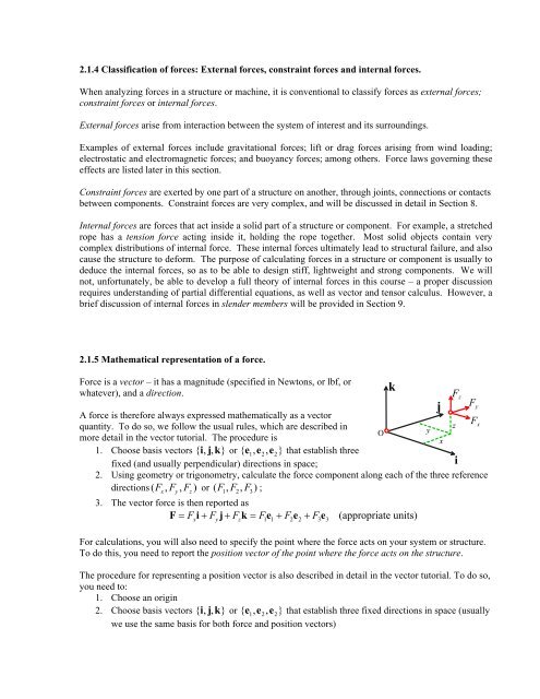
2.1.5 Mathematical representation <strong>of</strong> a force.<br />
Force is a vector – it has a magnitude (specified in Newtons, or lbf, or<br />
whatever), <strong>and</strong> a direction.<br />
A force is therefore always expressed mathematically as a vector<br />
F<br />
quantity. To do so, we follow the usual rules, which are described in<br />
z x<br />
O<br />
y<br />
more detail in the vector tutorial. The procedure is<br />
x<br />
1. Choose basis vectors { i, j, k } or { e1, e2, e<br />
2}<br />
that establish three<br />
fixed (<strong>and</strong> usually perpendicular) directions in space;<br />
i<br />
2. Using geometry or trigonometry, calculate the force component along each <strong>of</strong> the three reference<br />
directions ( Fx , Fy, F<br />
z)<br />
or ( F1, F2, F<br />
3)<br />
;<br />
3. The vector force is then reported as<br />
F= Fxi+ Fyj+ Fzk = F1e1+ F2e2+<br />
F3e<br />
3<br />
(appropriate units)<br />
For calculations, you will also need to specify the point where the force acts on your system or structure.<br />
To do this, you need to report the position vector <strong>of</strong> the point where the force acts on the structure.<br />
The procedure for representing a position vector is also described in detail in the vector tutorial. To do so,<br />
you need to:<br />
1. Choose an origin<br />
2. Choose basis vectors { i, j, k } or { e1, e2, e<br />
2}<br />
that establish three fixed directions in space (usually<br />
we use the same basis for both force <strong>and</strong> position vectors)<br />
k<br />
j<br />
F z<br />
F y