Chapter 2 Review of Forces and Moments - Brown University
Chapter 2 Review of Forces and Moments - Brown University
Chapter 2 Review of Forces and Moments - Brown University

You also want an ePaper? Increase the reach of your titles
YUMPU automatically turns print PDFs into web optimized ePapers that Google loves.
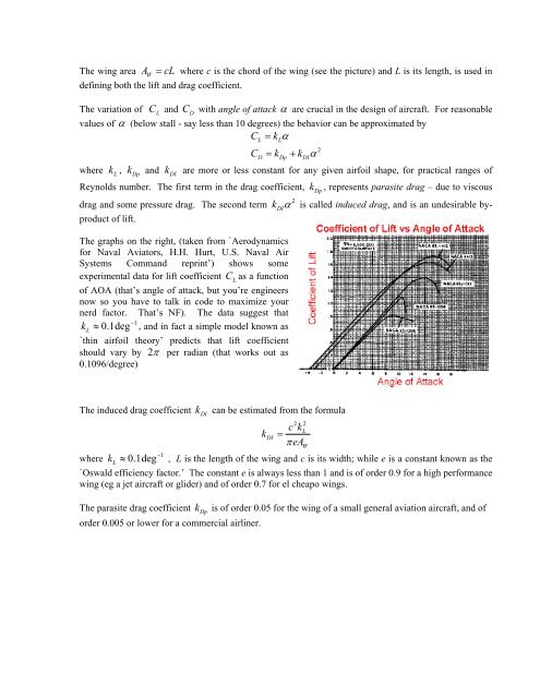
The wing area A cL W<br />
= where c is the chord <strong>of</strong> the wing (see the picture) <strong>and</strong> L is its length, is used in<br />
defining both the lift <strong>and</strong> drag coefficient.<br />
The variation <strong>of</strong> C<br />
L<br />
<strong>and</strong> C<br />
D<br />
with angle <strong>of</strong> attack α are crucial in the design <strong>of</strong> aircraft. For reasonable<br />
values <strong>of</strong> α (below stall - say less than 10 degrees) the behavior can be approximated by<br />
CL<br />
= kLα<br />
2<br />
CD = kDp + kDIα<br />
where k<br />
L<br />
, k<br />
Dp<br />
<strong>and</strong> k DI<br />
are more or less constant for any given airfoil shape, for practical ranges <strong>of</strong><br />
Reynolds number. The first term in the drag coefficient, k<br />
Dp<br />
, represents parasite drag – due to viscous<br />
2<br />
drag <strong>and</strong> some pressure drag. The second term kDIα is called induced drag, <strong>and</strong> is an undesirable byproduct<br />
<strong>of</strong> lift.<br />
The graphs on the right, (taken from `Aerodynamics<br />
for Naval Aviators, H.H. Hurt, U.S. Naval Air<br />
Systems Comm<strong>and</strong> reprint’) shows some<br />
experimental data for lift coefficient CL<br />
as a function<br />
<strong>of</strong> AOA (that’s angle <strong>of</strong> attack, but you’re engineers<br />
now so you have to talk in code to maximize your<br />
nerd factor. That’s NF). The data suggest that<br />
−1<br />
k L<br />
≈ 0.1deg , <strong>and</strong> in fact a simple model known as<br />
`thin airfoil theory’ predicts that lift coefficient<br />
should vary by 2π per radian (that works out as<br />
0.1096/degree)<br />
The induced drag coefficient k<br />
DI<br />
can be estimated from the formula<br />
2 2<br />
ckL<br />
kDI<br />
=<br />
πeAW<br />
−1<br />
where k L<br />
≈ 0.1deg , L is the length <strong>of</strong> the wing <strong>and</strong> c is its width; while e is a constant known as the<br />
`Oswald efficiency factor.’ The constant e is always less than 1 <strong>and</strong> is <strong>of</strong> order 0.9 for a high performance<br />
wing (eg a jet aircraft or glider) <strong>and</strong> <strong>of</strong> order 0.7 for el cheapo wings.<br />
The parasite drag coefficient k<br />
Dp<br />
is <strong>of</strong> order 0.05 for the wing <strong>of</strong> a small general aviation aircraft, <strong>and</strong> <strong>of</strong><br />
order 0.005 or lower for a commercial airliner.