A Decimal-to-Decimal Antilogarithmic Converter - Homepage Usask ...
A Decimal-to-Decimal Antilogarithmic Converter - Homepage Usask ...
A Decimal-to-Decimal Antilogarithmic Converter - Homepage Usask ...

You also want an ePaper? Increase the reach of your titles
YUMPU automatically turns print PDFs into web optimized ePapers that Google loves.
A <strong>Decimal</strong>-<strong>to</strong>-<strong>Decimal</strong> <strong>Antilogarithmic</strong> <strong>Converter</strong><br />
Dongdong Chen, Yu Zhang, Li Chen, Daniel Teng, Khan Wahid and Seok-Bum Ko<br />
Department of Electrical and Computer Engineering<br />
University of Saskatchewan, Saska<strong>to</strong>on, Canada<br />
Abstract— This paper presents a novel design and<br />
implementation of a 7-digit fixed-point decimal-<strong>to</strong>-decimal<br />
antilogarithmic converter. A linear approximation algorithm is<br />
proposed and simulated in MATLAB models. The maximum<br />
absolute error of the proposed decimal antilogarithmic<br />
converter is in the range of -0.000999 E absolute 0.000857 and<br />
the maximum percent error is in the range of -0.000715 E percent<br />
0.000691. The proposed decimal-<strong>to</strong>-decimal antilogarithmic<br />
converter is modeled in VHDL and implemented using a Xilinx<br />
Virtex-II Pro P30 FPGA device. The converter is implemented<br />
using combinational logic only and it computes decimal<br />
antilogarithms results in a single clock cycle, running at 53.1<br />
MHz.<br />
Index Terms – <strong>Decimal</strong>-<strong>to</strong>-decimal <strong>Antilogarithmic</strong> <strong>Converter</strong>,<br />
FPGA<br />
I. INTRODUCTION<br />
The logarithm and antilogarithm are useful arithmetic<br />
concepts in several areas of science and engineering. Some<br />
applications of digital signal processing, such as 3-D graphics<br />
processing and image segmentation algorithm, are<br />
implemented by using logarithmic and antilogarithmic unit <strong>to</strong><br />
replace the normal computer arithmetic, due <strong>to</strong> its capability<br />
of reducing the heavy arithmetic calculation requirement and<br />
high power consumption. For instance, the multiplication and<br />
division can be simplified <strong>to</strong> the level of addition and<br />
subtraction.<br />
Nowadays, despite the widespread use of binary<br />
arithmetic, decimal computation still plays an important role<br />
in many areas such as some commercial, financial and<br />
Internet-based applications [1]. Recently, decimal hardware<br />
arithmetic unit is attracting more and more researchers’<br />
attention and the specifications for it has been added <strong>to</strong> the<br />
draft revision of IEEE-754 standard for Floating-Point<br />
arithmetic (IEEE-754r) [2]. In this paper, a straight-line<br />
approximation algorithm-based approach is proposed and<br />
analyzed <strong>to</strong> calculate antilogarithms of a 7-digit fixed-point<br />
decimal number. The 7-digit decimal number is compliant<br />
with the mantissa region of the decimal-32 floating point<br />
number in IEEE-754r. Furthermore, the hardware<br />
implementation of this decimal antilogarithmic unit is<br />
described. To our knowledge, this paper is the first publication<br />
for the decimal-<strong>to</strong>-decimal antilogarithmic converter which is<br />
compliant with IEEE-754r standard.<br />
The paper is organized as follows: Section II describes the<br />
straight-line approximation algorithm approaches for decimal<br />
antilogarithms calculation. In section III, a method for decimal<br />
CCECE/CCGEI May 5-7 2008 Niagara Falls. Canada<br />
978-1-4244-1643-1/08/$25.00 2008 IEEE<br />
linear approximation is described. Section IV depicts an<br />
overview of the architecture of the proposed decimal<br />
antilogarithmic units; Section V presents the implementation<br />
results on FPGA. Section VI gives the conclusions.<br />
II. DECIMAL ANTILOGARITHMIC ALGORITHM<br />
Mitchell firstly described a methodology <strong>to</strong> obtain<br />
antilogarithms of a binary number ( 2 ( bin ) ) based on a straightline<br />
approximation <strong>to</strong> the antilogarithms function [3]. Based<br />
on the Mitchell’s algorithm, several methodologies <strong>to</strong> obtain<br />
antilogarithms of a binary number based on a straight-line<br />
approximation and VLSI implementation are described in [4]-<br />
[5]. However, it is obvious that the method described above is<br />
error-prone because many fractions such as 0.1 can not be<br />
exactly represented as binary numbers. Using binary based<br />
approach, the errors generated by conversion between decimal<br />
and binary format can not be avoided. Therefore, there is a<br />
need for a new decimal antilogarithmic algorithm which is<br />
error-free in conversion between decimal and binary format.<br />
The decimal antilogarithm calculations are based on<br />
piecewise approximations <strong>to</strong> the antilogarithm curve of the<br />
decimal logarithm. A linear approximation algorithm <strong>to</strong><br />
( )<br />
calculate 10 dec is summarized as follows: Let M is the<br />
logarithm of a decimal number in which the characteristic of<br />
the logarithm is represented by k and the mantissa is<br />
represented by am + b . M is represented as equation (1).<br />
M = log ( dec) = k + 1+ 1 og ( m)<br />
= k + am + b . (1)<br />
( )<br />
10 10<br />
The antilogarithm of M is approximated by Anti log<br />
10(<br />
M ) ' .<br />
Anti log<br />
10( M ) = 10 M , (2)<br />
10 M log( ) 10 k 10<br />
am +<br />
= Anti M = b . (3)<br />
To achieve the antilogarithmic approximation, 10 k is obtained<br />
by shifting the result since characteristic k is the 1-digit<br />
integer. The approximation of logarithm am + b is the 6-digit<br />
fraction bounded by 0≤ am + b < 1, so 10 am+ b is obtained by<br />
approximation.<br />
k<br />
Anti log<br />
10( M )' = 10 ( cm + d ) . (4)<br />
The absolute error is defined as:<br />
k am+<br />
b<br />
Eabs<br />
= 10 (10 − ( cm+ d))<br />
. (5)<br />
The percent error is defined as:<br />
cm + d<br />
E<br />
per<br />
= 1− . (6)<br />
10<br />
am+<br />
b<br />
001223<br />
Authorized licensed use limited <strong>to</strong>: University of Saskatchewan. Downloaded on January 27, 2010 at 02:09 from IEEE Xplore. Restrictions apply.
For example, a decimal logarithm M is assumed<br />
as M = 4.514562 , which represents the logarithm of a 7-digit<br />
fixed-point number, and it is consistent with the mantissa<br />
region of the decimal-32 floating point number in IEEE-754r.<br />
According <strong>to</strong> the algorithm described above,<br />
4 0.514562<br />
10 M log( ) 10 k 10 am +<br />
= Anti M = b = 10 10 in which<br />
10 am+ b is achieved by a linear approximation and 10 k is<br />
obtained by a shift operation.<br />
The mean-squared error is defined as (7), here, 1>m 2 mm 1 0<br />
2<br />
2 1 m2<br />
am+<br />
b<br />
E = { 10 − ( cm+<br />
d)<br />
} dm<br />
m − m<br />
. (7)<br />
m1<br />
To minimize<br />
2 1<br />
2<br />
E with respect <strong>to</strong> c and d, it is necessary that<br />
2<br />
∂E<br />
2<br />
+<br />
= 0= −2 {(10 ) − ( + )}<br />
∂<br />
m am b<br />
m cm d dm, (8)<br />
c<br />
m1<br />
2<br />
∂E<br />
2<br />
+<br />
= 0= −2 {(10 ) − ( + )}<br />
∂<br />
m am b<br />
cm d dm . (9)<br />
d<br />
m1<br />
Thus, according <strong>to</strong> (7), (8), and (9), the coefficients c and<br />
d can be determined <strong>to</strong> achieve the minimal mean-squared<br />
error for any partition of the interval [0,1) . The minimal<br />
mean-squared error was used <strong>to</strong> determine c and d in binary<br />
antilogarithms [6]. However, <strong>to</strong> guarantee certain accuracy,<br />
the maximal absolute error is the better parameter than the<br />
mean squared error and the percent error. Thus, tuning the<br />
obtained coefficients is proposed as a means <strong>to</strong> achieve the<br />
minimum absolute error. Figure 1 demonstrates the<br />
optimization of linear approximation for minimum absolute<br />
error in 1 partition, in which the curve of the original absolute<br />
error is moved and the optimized absolute error is reduced<br />
from the original linear approximation’s 1.945 <strong>to</strong> 1.214.<br />
the same dynamic range of 9-bit binary accuracy, is<br />
sufficiently accurate for some DSP applications. This method<br />
determines the bound of partition regions as well as the<br />
coefficients of linear approximation in each region. The<br />
optimized coefficients can guarantee minimum absolute error<br />
with relative small mean-squared error with least partition<br />
region numbers.<br />
First, the absolute error restriction for achieving 10 -3<br />
accuracy of antilogarithm, and the initial bound of partition<br />
region are set. Second, a tuning region for coefficients<br />
optimization is manually defined, in which the determined<br />
coefficients according <strong>to</strong> (7), (8) and (9) are adjusted and the<br />
partition region is corrected simultaneously <strong>to</strong> keep maximal<br />
absolute errors smaller than the absolute error restriction.<br />
Thus, the bound of partition regions and coefficients can<br />
acquire the minimum error. After optimization, the decimal<br />
logarithmic curve is divided in<strong>to</strong> 36 partition regions. To<br />
minimize the complexity of the implementation of the<br />
antilogarithmic unit while keeping the accuracy of 10 -3 , the<br />
coefficients, c and d are truncated <strong>to</strong> 5 digits, respectively. In<br />
doing so 45 partition regions are obtained. The result of<br />
c(5digits)×m(5digits)+d(5digits) gives the result for<br />
implementing linear approximation of the decimal<br />
antilogarithmic unit and guarantee 10 -3 accuracy for any 7-<br />
digit fixed-point decimal number. Table I shows the<br />
coefficients and bound of partition regions, maximal positive<br />
and negative absolute errors of the proposed decimal-<strong>to</strong>decimal<br />
antilogarithmic unit.<br />
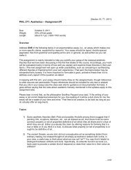
NO<br />
YES<br />
Y=1?<br />
START<br />
Determine the bound of partition<br />
[X, Y] , Initial X=L_min, Initial Y=L_min+STEP<br />
STEP=0.001<br />
Decide the coefficients c and d<br />
for mean-squared error<br />
NO<br />
YES<br />
Y=1?<br />
10<br />
8<br />
6<br />
Linear Approxmation Analysis of <strong>Decimal</strong> Antilog<br />
10 m curve<br />
Original Linear Approxmation<br />
Adjusted Linear Approximation<br />
Original Absolute Error<br />
Optimized Absolute Error<br />
Original Max Absolute Error<br />
Optimized Max Absolute Error<br />
X=X<br />
Y=Y+STEP<br />
Define the Tuning Range manually and<br />
adjust the coefficients for minimum error<br />
YES<br />
Minimum<br />
Error
TABLE I.<br />
PARAMETERS OF LINEAR APPROXIMATION FOR A DECIMAL ANTILOGARITHMIC CONVERTER<br />
Partition Region c d Max +Abs Error Max –Abs Error<br />
1 [0.000 0.039] 2.4248 0.99930 0.684317E-3 -0.930285E-3<br />
2 [0.040 0.084] 2.6616 0.98923 0.798574E-3 -0.809191E-3<br />
3 [0.085 0.129] 2.9496 0.96463 0.856913E-3 -0.867725E-3<br />
4 [0.130 0.172] 3.2627 0.92397 0.844411E-3 -0.872633E-3<br />
5 [0.173 0.211] 3.5844 0.86844 0.679335E-3 -0.853829E-3<br />
6 [0.212 0.249] 3.9171 0.79815 0.841876E-3 -0.893172E-3<br />
7 [0.250 0.286] 4.2745 0.70872 0.756582E-3 -0.799898E-3<br />
8 [0.287 0.322] 4.6438 0.60283 0.823262E-3 -0.865506E-3<br />
9 [0.323 0.356] 5.0362 0.47630 0.846450E-3 -0.923869E-3<br />
10 [0.357 0.387] 5.4275 0.33669 0.671638E-3 -0.732032E-3<br />
11 [0.388 0.417] 5.8208 0.18416 0.644767E-3 -0.855853E-3<br />
12 [0.418 0.446] 6.2299 0.01338 0.738941E-3 -0.897674E-3<br />
13 [0.447 0.476] 6.6694 -0.18309 0.829339E-3 -0.913325E-3<br />
14 [0.477 0.500] 7.1005 -0.38826 0.696594E-3 -0.754848E-3<br />
15 [0.501 0.520] 7.4799 -0.57838 0.406162E-3 -0.530416E-3<br />
16 [0.521 0.546] 7.8739 -0.78415 0.718181E-3 -0.868334E-3<br />
17 [0.547 0.569] 8.3263 -1.0313 0.677309E-3 -0.602936E-3<br />
18 [0.570 0.590] 8.7566 -1.2764 0.534182E-3 -0.575841E-3<br />
19 [0.591 0.612] 9.2010 -1.5389 0.656037E-3 -0.618655E-3<br />
20 [0.613 0.635] 9.6902 -1.8387 0.718669E-3 -0.742884E-3<br />
21 [0.636 0.653] 10.164 -2.1397 0.375793E-3 -0.632906E-3<br />
22 [0.654 0.672] 10.618 -2.4367 0.476620E-3 -0.797813E-3<br />
23 [0.673 0.692] 11.078 -2.7462 0.603285E-3 -0.729004E-3<br />
24 [0.693 0.711] 11.590 -3.1006 0.574145E-3 -0.661232E-3<br />
25 [0.712 0.728] 12.101 -3.4645 0.655445E-4 -0.961083E-3<br />
26 [0.729 0.748] 12.628 -3.8487 0.622556E-3 -0.701621E-3<br />
27 [0.749 0.765] 13.150 -4.2394 0.364906E-3 -0.812337E-3<br />
28 [0.766 0.779] 13.632 -4.6080 0.289514E-3 -0.544311E-3<br />
29 [0.780 0.791] 14.046 -4.9308 0.000000E-3 -0.717038E-3<br />
30 [0.792 0.803] 14.464 -5.2614 0.288500E-3 -0.463958E-3<br />
31 [0.804 0.818] 14.900 -5.6123 0.173857E-3 -0.825859E-3<br />
32 [0.819 0.833] 15.424 -6.0409 0.477911E-3 -0.554259E-3<br />
33 [0.834 0.848] 15.966 -6.4928 0.347947E-3 -0.720727E-3<br />
34 [0.849 0.863] 16.527 -6.9689 0.269096E-3 -0.837693E-3<br />
35 [0.864 0.878] 17.108 -7.4705 0.376626E-3 -0.767618E-3<br />
36 [0.879 0.893] 17.717 -8.0057 0.258218E-3 -0.958477E-3<br />
37 [0.894 0.905] 18.289 -8.5168 0.176663E-4 -0.931448E-3<br />
38 [0.906 0.919] 18.844 -9.0196 0.324158E-3 -0.658204E-3<br />
39 [0.920 0.932] 19.439 -9.5669 0.271120 E-3 -0.883869E-3<br />
40 [0.933 0.947] 20.098 -10.182 0.504407E-3 -0.855058E-3<br />
41 [0.948 0.961] 20.756 -10.806 0.268748E-3 -0.821870E-3<br />
42 [0.962 0.972] 21.338 -11.365 0.547859E-3 -0.295290E-3<br />
43 [0.973 0.983] 21.883 -11.895 0.526360E-3 -0.350400E-3<br />
44 [0.984 0.994] 22.438 -12.441 0.287008E-3 -0.644965E-3<br />
45 [0.995 0.999] 22.878 -12.878 0.206594E-3 -0.226477E-3<br />
1.5 x 10⁻³ <strong>Decimal</strong> Linear Approximation Absolute Error Analysis<br />
Absolute Error<br />
Max.+ Absolute Error<br />
1 Max. - Absolute Error<br />
1.5 x 10⁻³ <strong>Decimal</strong> Linear Approximation Percent Error Analysis<br />
Percent Error<br />
Max.+ Percent Error<br />
1 Max. - Percent Error<br />
0.5<br />
0.5<br />
Absolute Error<br />
0<br />
Percent Error<br />
0<br />
-0.5<br />
-0.5<br />
-1<br />
-1<br />
-1.5<br />
10 0 10 1 10 2 10 3 10 4 10 5<br />
The N value<br />
-1.5<br />
10 0 10 1 10 2 10 3 10 4 10 5<br />
The N value<br />
Figure 3. Absolute Error Analysis of <strong>Decimal</strong> <strong>Antilogarithmic</strong> <strong>Converter</strong><br />
Figure 4. Percent Error Analysis of <strong>Decimal</strong> <strong>Antilogarithmic</strong> <strong>Converter</strong><br />
001225<br />
Authorized licensed use limited <strong>to</strong>: University of Saskatchewan. Downloaded on January 27, 2010 at 02:09 from IEEE Xplore. Restrictions apply.
IV. HARDWARE IMPLEMENTATION<br />
Figure 5 shows the architecture of the proposed 7-digit<br />
fixed-point decimal antilogarithmic converter. It takes one<br />
clock cycle <strong>to</strong> achieve the approximation result of the<br />
antilogarithms of a 7-digit fixed-point decimal number. The<br />
hardware implementation of this antilogarithmic converter<br />
includes three parts. The first part consisted of a characteristic<br />
decoder tells the shifter register how many digits should be<br />
shifted according <strong>to</strong> the characteristic part of logarithms; the<br />
second part mainly composed of a size of 2 7 × 20coefficients<br />
ROM and the linear approximation logic completes the<br />
decimal linear approximation of antilogarithms; the third part<br />
is a shifter which can shift the linear approximation result <strong>to</strong><br />
correct antilogarithm.<br />
detail in [7], and then the linear approximation is achieved by<br />
the carry-save-tree and carry-propagation-addition. The<br />
decimal antilogarithmic converter is implemented only using<br />
combinational logic so that antilogarithm results can be<br />
obtained in a single clock cycle.<br />
V. IMPLEMENTATION RESULTS<br />
The proposed architecture based on decimal linear<br />
approximation algorithm for decimal-<strong>to</strong>-decimal<br />
antilogarithmic converter is modeled in VHDL and<br />
implemented using a Xilinx Virtex2p XC2VP30 FPGA board<br />
with package ff1517 and speed -7. The implementation results<br />
of this decimal-<strong>to</strong>-decimal antilogarithmic convert are shown<br />
in Table II.<br />
TABLE II. IMPLEMENTATION RESULTS<br />
Xilinx Virtex2p XC2VP30 Device Utilization Summary<br />
Logic Utilization Used Available Utilization<br />
Number of occupied Slices 1077 13696 7%<br />
Maximum Frequency<br />
53.1 MHz<br />
Latency<br />
1 clock cycle<br />
7<br />
2 × 20<br />
Figure 5. Architecture of Proposed <strong>Decimal</strong> <strong>Antilogarithmic</strong> <strong>Converter</strong><br />
At the beginning, a 7-digit fixed-point number is<br />
represented by 28-bit BCD code. The 28-bit BCD code<br />
includes 4-bit characteristic or integer part and 24-bit mantissa<br />
part which are format of decimal logarithm result. The shifter<br />
detec<strong>to</strong>r determines how many digits should be shifted in<br />
shifter register according <strong>to</strong> the characteristic part of<br />
logarithms. The mantissa part of logarithms is sent <strong>to</strong> the<br />
coefficients detec<strong>to</strong>r and the corresponding coefficients are<br />
chosen from the ROM (realized by dual port BRAM IP<br />
provided by XILINX) according <strong>to</strong> the 4-bit signal from<br />
coefficients detec<strong>to</strong>r. The coefficient c is multiplied with 5-<br />
digit of MSB of m and then added <strong>to</strong> the coefficient d. Finally,<br />
the result of c(5digits)×m(5digits)+d(5digits) is shifted<br />
according <strong>to</strong> the signal from shifter detec<strong>to</strong>r. The results from<br />
shifter register are used for linear approximation for decimal<br />
antilogarithmic unit.<br />
The linear approximation logic can be realized by a<br />
combinational decimal multiplication and a decimal addition.<br />
To reduce the circuit complexity and improve the performance<br />
of <strong>Antilogarithmic</strong> converter, the architecture of linear<br />
approximation logic is designed according <strong>to</strong> the literature [7]-<br />
[8]. A 1-digit decimal carry-look-ahead adder is designed<br />
according <strong>to</strong> the literature [8], and this decimal carry-lookahead<br />
adder is used <strong>to</strong> create a carry-save-adder tree. When<br />
the 5-digit coefficients and 5-digit m are sent <strong>to</strong> the linear<br />
approximation logic, the partial product is firstly generated in<br />
the block of partial product generation which is presented in<br />
VI. CONCLUSIONS<br />
The proposed decimal antilogarithmic converter based on<br />
decimal linear approximation algorithm can guarantee 10 -3<br />
accuracy for any 7-digit fixed-point decimal number. It a) is<br />
error-free in conversion between decimal and binary format,<br />
and b) uses the optimization process of linear approximation<br />
for minimal absolute error. The decimal antilogarithmic<br />
converter takes one clock cycle <strong>to</strong> achieve the approximation<br />
result. We believe, the presented architecture can be modified<br />
<strong>to</strong> reduce complexity and in turns, achieves higher speed and<br />
less area.<br />
ACKNOWLEDGMENT<br />
The authors would like <strong>to</strong> acknowledge the Natural<br />
Science and Engineering Research Council of Canada<br />
(NSERC) for its support <strong>to</strong> this research work.<br />
REFERENCES<br />
[1] M. Cowlishaw, “<strong>Decimal</strong> Floating-Point: Algorism for Computers,”<br />
IEEE Symp.on Computer Arithmetic, pp. 104-111, Jun. 2003.<br />
[2] 754 Working Group. Draft IEEE Standard for Floating-Point<br />
Arithmetic. Available at http://754r.ucbtest.org/drafts/<br />
[3] J. Mitchell Jr., “Computer Multiplication and Division Using Binary<br />
Logarithms,” IRE Trans. Elect. Comp., vol. 11, pp. 512-517, Aug. 1962.<br />
[4] E. Hall, D. Lynch, and S. Dwyer, “Generation of Products and<br />
Quotients Using Approximate Binary Logarithms for Digital Filtering<br />
Applications,” IEEE Trans. Computers, vol. 19, pp. 97-105, Feb. 1970.<br />
[5] K. H. Abed and Raymond E. Siferd, “VLSI implementation of a lowpower<br />
<strong>Antilogarithmic</strong> converter,” IEEE Trans. Comput., vol. 52, no. 9,<br />
pp. 1421–1433, Sep. 2003.<br />
[6] E.L. Hall, D.D. Lynch, and S.J. Dwyer, “Generation of Products and<br />
Quotients Using Approximate Binary Logarithms for Digital Filtering<br />
Applications,” IEEE Trans. Computers, vol. 19, pp. 97-105, Feb. 1970.<br />
[7] T. Lang and A. Nannarelli, “A Radix-10 Combinational Multiplier,”<br />
Asilomar Conference on Signals, Systems and Computers, pp. 313-317,<br />
Oct. 2006.<br />
[8] Y. You, Y. Kim and J. Choi, “Dynamic <strong>Decimal</strong> Adder Circuit Design<br />
by using the Carry Lookahead,” IEEE Design and Diagnostics of<br />
Electronic Circuits and systems, pp. 242-244, Apr. 2006.<br />
001226<br />
Authorized licensed use limited <strong>to</strong>: University of Saskatchewan. Downloaded on January 27, 2010 at 02:09 from IEEE Xplore. Restrictions apply.