Etude de la combustion de gaz de synthèse issus d'un processus de ...
Etude de la combustion de gaz de synthèse issus d'un processus de ... Etude de la combustion de gaz de synthèse issus d'un processus de ...
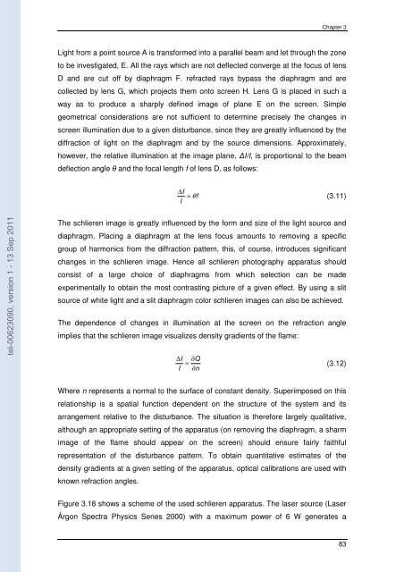
Chapter 3 Light from a point source A is transformed into a parallel beam and let through the zone to be investigated, E. All the rays which are not deflected converge at the focus of lens D and are cut off by diaphragm F. refracted rays bypass the diaphragm and are collected by lens G, which projects them onto screen H. Lens G is placed in such a way as to produce a sharply defined image of plane E on the screen. Simple geometrical considerations are not sufficient to determine precisely the changes in screen illumination due to a given disturbance, since they are greatly influenced by the diffraction of light on the diaphragm and by the source dimensions. Approximately, however, the relative illumination at the image plane, ∆I/I, is proportional to the beam deflection angle θ and the focal length f of lens D, as follows: ∆I ≈ θf (3.11) I tel-00623090, version 1 - 13 Sep 2011 The schlieren image is greatly influenced by the form and size of the light source and diaphragm. Placing a diaphragm at the lens focus amounts to removing a specific group of harmonics from the diffraction pattern, this, of course, introduces significant changes in the schlieren image. Hence all schlieren photography apparatus should consist of a large choice of diaphragms from which selection can be made experimentally to obtain the most contrasting picture of a given effect. By using a slit source of white light and a slit diaphragm color schlieren images can also be achieved. The dependence of changes in illumination at the screen on the refraction angle implies that the schlieren image visualizes density gradients of the flame: ∆I ∂Q ≈ (3.12) I ∂ n Where n represents a normal to the surface of constant density. Superimposed on this relationship is a spatial function dependent on the structure of the system and its arrangement relative to the disturbance. The situation is therefore largely qualitative, although an appropriate setting of the apparatus (on removing the diaphragm, a sharm image of the flame should appear on the screen) should ensure fairly faithful representation of the disturbance pattern. To obtain quantitative estimates of the density gradients at a given setting of the apparatus, optical calibrations are used with known refraction angles. Figure 3.18 shows a scheme of the used schlieren apparatus. The laser source (Laser Árgon Spectra Physics Series 2000) with a maximum power of 6 W generates a 83
Experimental set ups and diagnostics continuous beam of light, composed for two respectively equal main rays with wave length of 488 and 514.5 nm. This laser beam is cut, by the acoustic-optical deflector (Errol) in a succession of luminous impulses of adjustable duration and frequency. At the exit of the acoustic-optical deflector, the rays cross a convergent lens making them to converge into a focal point in the image where is placed a diaphragm of 50µ diameter. The diaphragm is placed in the center of the object of a spherical mirror with focal length of 1m, in order to reflecting the luminous rays into a parallel beam that crosses the combustion chamber (Taillefet, 1999). tel-00623090, version 1 - 13 Sep 2011 Figure 3.18– Schlieren scheme (Malheiro, 2002) When a phenomenon in the chamber cause a change of the refractive index, the light is deviated and passes with the same dimensions to the screen that can be record by a camera. To this end, a fast camera APX RS PHOTRON (CMOS, 10 bits, run at 6000 fps, 1024×512 pixels) is used to record the schlieren flame images during combustion. Exposure time is imposed by the acoustic-optical deflector and is fixed to 5 ms. 84
- Page 35 and 36: Bibliographic revision established
- Page 37 and 38: Bibliographic revision Hydrogen Hyd
- Page 39 and 40: Bibliographic revision of low moist
- Page 41 and 42: Bibliographic revision scrubbing an
- Page 43 and 44: Bibliographic revision suggests tha
- Page 45 and 46: Bibliographic revision 1 d( δ A) 1
- Page 47 and 48: Bibliographic revision Since n is
- Page 49 and 50: Bibliographic revision 2 ( rsr ) 2
- Page 51 and 52: Bibliographic revision This evoluti
- Page 53 and 54: Bibliographic revision The burning
- Page 55 and 56: Bibliographic revision δVG = − a
- Page 57 and 58: Bibliographic revision 2 1 − −
- Page 59 and 60: Bibliographic revision where the su
- Page 61 and 62: Bibliographic revision the stretche
- Page 63 and 64: Bibliographic revision burning velo
- Page 65 and 66: Experimental set ups and diagnostic
- Page 67 and 68: Experimental set ups and diagnostic
- Page 69 and 70: Experimental set ups and diagnostic
- Page 71 and 72: Experimental set ups and diagnostic
- Page 73 and 74: Experimental set ups and diagnostic
- Page 75 and 76: Experimental set ups and diagnostic
- Page 77 and 78: Experimental set ups and diagnostic
- Page 79 and 80: Experimental set ups and diagnostic
- Page 81 and 82: Experimental set ups and diagnostic
- Page 83 and 84: Experimental set ups and diagnostic
- Page 85: Experimental set ups and diagnostic
- Page 89 and 90: Chapter 4 CHAPTER 4 EXPERIMENTAL AN
- Page 91 and 92: Chapter 4 4.1 Laminar burning veloc
- Page 93 and 94: Chapter 4 4.1.1.1 Flame morphology
- Page 95 and 96: Chapter 4 P i = 1.0 bar, Ti = 293 K
- Page 97 and 98: Chapter 4 Figure 4.5 shows schliere
- Page 99 and 100: Chapter 4 P i = 2.0 bar, T i = 293
- Page 101 and 102: Chapter 4 Sn (m/s) 3.0 2.5 2.0 1.5
- Page 103 and 104: Chapter 4 5 ms 10 ms 15 ms 20 ms 25
- Page 105 and 106: Chapter 4 behaviour of the curves r
- Page 107 and 108: Chapter 4 1.50 Sn (m/s) 1.25 1.00 0
- Page 109 and 110: Chapter 4 0.5 0.4 φ =1.0 Su (m/s)
- Page 111 and 112: Chapter 4 variation of the normaliz
- Page 113 and 114: Chapter 4 4.1.1.6 Comparison with o
- Page 115 and 116: Chapter 4 The values of laminar bur
- Page 117 and 118: Chapter 4 Pressure (bar) 7 6 5 4 3
- Page 119 and 120: Chapter 4 0.5 0.4 φ=1.2 Su (m/s) 0
- Page 121 and 122: Chapter 4 0.3 φ=0.8 Su (m/s) 0.2 0
- Page 123 and 124: Chapter 4 a minimum pressure to exp
- Page 125 and 126: Chapter 4 Notice the similar behavi
- Page 127 and 128: Chapter 4 A very good agreement bet
- Page 129 and 130: Chapter 4 ( ) Q = h T − T (4.21)
- Page 131 and 132: Chapter 4 tel-00623090, version 1 -
- Page 133 and 134: Chapter 4 are tested and discussed.
- Page 135 and 136: Chapter 4 7 500 Pressure (bar) 6 5
Chapter 3<br />
Light from a point source A is transformed into a parallel beam and let through the zone<br />
to be investigated, E. All the rays which are not <strong>de</strong>flected converge at the focus of lens<br />
D and are cut off by diaphragm F. refracted rays bypass the diaphragm and are<br />
collected by lens G, which projects them onto screen H. Lens G is p<strong>la</strong>ced in such a<br />
way as to produce a sharply <strong>de</strong>fined image of p<strong>la</strong>ne E on the screen. Simple<br />
geometrical consi<strong>de</strong>rations are not sufficient to <strong>de</strong>termine precisely the changes in<br />
screen illumination due to a given disturbance, since they are greatly influenced by the<br />
diffraction of light on the diaphragm and by the source dimensions. Approximately,<br />
however, the re<strong>la</strong>tive illumination at the image p<strong>la</strong>ne, ∆I/I, is proportional to the beam<br />
<strong>de</strong>flection angle θ and the focal length f of lens D, as follows:<br />
∆I<br />
≈ θf<br />
(3.11)<br />
I<br />
tel-00623090, version 1 - 13 Sep 2011<br />
The schlieren image is greatly influenced by the form and size of the light source and<br />
diaphragm. P<strong>la</strong>cing a diaphragm at the lens focus amounts to removing a specific<br />
group of harmonics from the diffraction pattern, this, of course, introduces significant<br />
changes in the schlieren image. Hence all schlieren photography apparatus should<br />
consist of a <strong>la</strong>rge choice of diaphragms from which selection can be ma<strong>de</strong><br />
experimentally to obtain the most contrasting picture of a given effect. By using a slit<br />
source of white light and a slit diaphragm color schlieren images can also be achieved.<br />
The <strong>de</strong>pen<strong>de</strong>nce of changes in illumination at the screen on the refraction angle<br />
implies that the schlieren image visualizes <strong>de</strong>nsity gradients of the f<strong>la</strong>me:<br />
∆I<br />
∂Q<br />
≈ (3.12)<br />
I ∂ n<br />
Where n represents a normal to the surface of constant <strong>de</strong>nsity. Superimposed on this<br />
re<strong>la</strong>tionship is a spatial function <strong>de</strong>pen<strong>de</strong>nt on the structure of the system and its<br />
arrangement re<strong>la</strong>tive to the disturbance. The situation is therefore <strong>la</strong>rgely qualitative,<br />
although an appropriate setting of the apparatus (on removing the diaphragm, a sharm<br />
image of the f<strong>la</strong>me should appear on the screen) should ensure fairly faithful<br />
representation of the disturbance pattern. To obtain quantitative estimates of the<br />
<strong>de</strong>nsity gradients at a given setting of the apparatus, optical calibrations are used with<br />
known refraction angles.<br />
Figure 3.18 shows a scheme of the used schlieren apparatus. The <strong>la</strong>ser source (Laser<br />
Árgon Spectra Physics Series 2000) with a maximum power of 6 W generates a<br />
83


