Caged Ball LM Guide SPR/SPS - THK Technical Support
Caged Ball LM Guide SPR/SPS - THK Technical Support
Caged Ball LM Guide SPR/SPS - THK Technical Support

You also want an ePaper? Increase the reach of your titles
YUMPU automatically turns print PDFs into web optimized ePapers that Google loves.
<strong>Caged</strong> <strong>Ball</strong><br />
<strong>LM</strong> <strong>Guide</strong><br />
<strong>SPR</strong> / <strong>SPS</strong><br />
Adopts 8 Rows of Raceways<br />
Achieves Super-Low Waving and Ultra-High Rigidity<br />
For details, visit <strong>THK</strong> at www.thk.com<br />
Product information is updated regularly on the <strong>THK</strong> website.<br />
CATALOG No.362-1E
aged <strong>Ball</strong><br />
M <strong>Guide</strong><br />
New Advanced <strong>LM</strong> <strong>Guide</strong><br />
Achieves super-low waving and ultra-high rigidity by adopting<br />
8 rows of raceways in the <strong>LM</strong> <strong>Guide</strong>.<br />
These models adopt (1) 8 rows of raceways, (2) small-diameter balls and (3) super-long<br />
blocks, in order to realize super-low waving and ultra-high rigidity that surpass the<br />
conventional <strong>LM</strong> <strong>Guide</strong>. With this approach, the number of effective balls is<br />
substantially increased, and the amplitude of the rolling element in motion is<br />
minimized. The new models realize super-low waving comparable to hydrostatic<br />
guides. In addition, the deformation of the ball is minimized to achieve ultra-high<br />
rigidity that surpasses even roller guides. The two models contribute to higher<br />
accuracy of equipment.
Cross section of<br />
Radial type model <strong>SPR</strong><br />
<br />
<br />
<br />
<br />
Cross section of<br />
4-way type model <strong>SPS</strong><br />
Primary applications<br />
Super-precision processing machines/High-precision machining center<br />
/Lathe/Surface grinder/Semiconductor manufacturing equipment/<br />
FPD manufacturing machines/High-performance measuring machines
aged <strong>Ball</strong><br />
M <strong>Guide</strong><br />
<br />
<br />
Super-low waving and ultra-high rigidity have been verified.<br />
[Waving evaluation]<br />
The waving values of models <strong>SPR</strong>/<strong>SPS</strong><br />
are approximately 1/10 of that (100 to 300 nm)<br />
of conventional ordinary <strong>LM</strong> <strong>Guide</strong>s.<br />
Conditions<br />
Tested model<br />
Rail span<br />
Block span<br />
Measurement point<br />
Measurement direction<br />
<strong>SPS</strong>25LR<br />
250mm<br />
250mm<br />
250 mm above the center of the table<br />
Vertical and horizontal<br />
Appearance of the specimen<br />
<br />
Waving (vertical direction)<br />
Deflectionm Deflectionm<br />
Straightness (vertical direction)<br />
<br />
<br />
<br />
<br />
<br />
<br />
<br />
<br />
Strokemm <br />
Straightness (horizontal direction)<br />
<br />
<br />
<br />
<br />
<br />
<br />
<br />
<br />
Strokemm<br />
[Rigidity comparison evaluation]<br />
Models <strong>SPR</strong>/<strong>SPS</strong> achieve very high rigidity.<br />
Deflectionm<br />
Deflectionm<br />
<br />
<br />
<br />
<br />
<br />
Strokemm<br />
<br />
<br />
<br />
Waving (horizontal direction)<br />
<br />
<br />
<br />
Strokemm<br />
* Internal evaluation record<br />
Deflectionm<br />
<br />
<br />
<br />
<br />
<br />
<strong>SPS</strong>25LR<br />
Roller guide<br />
Conventional ball guide<br />
Radial rigidity<br />
Deflectionm<br />
<br />
<br />
<br />
<br />
<br />
Reverse radial rigidity<br />
<strong>SPS</strong>25LR<br />
Roller guide<br />
Conventional ball guide<br />
<br />
<br />
Applied loadkN<br />
<br />
<br />
Applied loadkN<br />
* This test was intended to compare the clearance C1.
Product Overview<br />
<strong>Caged</strong> <strong>Ball</strong> <strong>LM</strong> <strong>Guide</strong> <br />
Rated Loads in All Directions<br />
Models <strong>SPR</strong>/<strong>SPS</strong> are capable of receiving loads in all four directions: radial, reverse-radial and lateral directions.<br />
The basic load ratings of model <strong>SPR</strong> are represented by the symbols in the radial direction indicated in the fi gure on the right,<br />
and the actual values are provided in the dimensional tables* 1 for <strong>SPR</strong>. The values in the reverse-radial and lateral directions<br />
of model <strong>SPR</strong> are obtained from the table.<br />
The basic load ratings of model <strong>SPS</strong> are equal in all the four directions (radial, reverse radial and lateral directions), and their<br />
actual values are provided in the specifi cation table* 1 for <strong>SPS</strong>.<br />
<br />
Rated Loads in All Directions with Model <strong>SPR</strong><br />
<br />
<br />
<br />
Model <strong>SPR</strong><br />
Direction Basic dynamic<br />
load rating<br />
Basic static<br />
load rating<br />
Radial direction C C 0<br />
Reverse-radial<br />
direction<br />
C L=0.71C C 0L=0.71C 0<br />
Lateral direction C T=0.44C C 0T=0.35C 0<br />
<br />
<br />
<br />
<br />
<br />
<br />
*1: Dimensional table for models <strong>SPR</strong>/<strong>SPS</strong><br />
Model <strong>SPR</strong>-LR page 9<br />
Model <strong>SPS</strong>-LR page 11<br />
Equivalent Load<br />
When the <strong>LM</strong> block of model <strong>SPR</strong> receives a reverse-radial load and a lateral load simultaneously, the equivalent load is<br />
obtained from the equation below.<br />
<br />
Equivalent Factor of Model <strong>SPR</strong><br />
P E X Y<br />
Equivalent load in reverseradial<br />
direction<br />
1 2<br />
PE Equivalent load [N]<br />
Note: If a reverse-radial load and a horizontal load are simultaneously applied,<br />
calculate the equivalent reverse-radial load.<br />
Reverse-radial direction<br />
PL Reverse-radial load [N]<br />
PT Lateral load [N]<br />
X, Y Equivalent factor<br />
When the <strong>LM</strong> block of model <strong>SPS</strong> receives loads in all directions simultaneously, the equivalent load is obtained from the<br />
equation below.<br />
PE<br />
Equivalent load [N]<br />
Radial direction<br />
Reverse-radial direction<br />
PR Radial load [N]<br />
PL<br />
PT<br />
Reverse-radial load [N]<br />
Lateral load [N]
Product Overview<br />
<strong>Caged</strong> <strong>Ball</strong> <strong>LM</strong> <strong>Guide</strong> <br />
Service life<br />
The service life of an <strong>LM</strong> <strong>Guide</strong> is subject to variations even under the same operational conditions. Therefore, it is necessary<br />
to use the nominal life defi ned below as a reference value for obtaining the service life of the <strong>LM</strong> <strong>Guide</strong>.<br />
[Nominal life]<br />
The nominal life means the total travel distance that 90% of<br />
a group of units of the same <strong>LM</strong> <strong>Guide</strong> model can achieve<br />
without fl aking (scale-like pieces on the metal surface) after<br />
individually running under the same conditions.<br />
<br />
<br />
<br />
<br />
*1 : Basic dynamic load rating (C)<br />
It refers to a load with a constant magnitude and direction under<br />
which the nominal life (L) of a group of identical <strong>LM</strong> <strong>Guide</strong> units<br />
independently operating is 50 km.<br />
L : Nominal life [km]<br />
C : Basic dynamic load rating* 1 [N]<br />
PC : Calculated load [N]<br />
fH : Hardness factor (see Fig.1)<br />
fT : Temperature factor<br />
fC : Contact factor (see Table1)<br />
fW : Load factor (see Table2)<br />
[Service life time]<br />
Once the nominal life (L) has been obtained, the service life<br />
time can be obtained using the equation on the right if the<br />
stroke length and the number reciprocations are constant.<br />
<br />
<br />
<br />
<br />
Lh : Service life time [h]<br />
s : Stroke length [mm]<br />
n1 : Number of reciprocations per minute [min -1 ]<br />
fH: Hardness Factor<br />
To ensure the achievement of the optimum load capacity of the <strong>LM</strong> <strong>Guide</strong>,<br />
the raceway hardness must be between 58 and 64 HRC.<br />
If the hardness is lower than this range, the basic dynamic load rating and<br />
the basic static load rating decrease. Therefore, it is necessary to multiply<br />
each rating by the respective hardness factor (fH).<br />
Since the <strong>LM</strong> <strong>Guide</strong> has suffi cient hardness, the fH value for the <strong>LM</strong> <strong>Guide</strong> is<br />
normally 1.0 unless otherwise specifi ed.<br />
Hardness factor fH<br />
1.0<br />
0.9<br />
0.8<br />
0.7<br />
0.6<br />
0.5<br />
0.4<br />
0.3<br />
0.2<br />
0.1<br />
60 50 40 30 20 10<br />
Raceway hardness (HRC)<br />
Fig.1 Hardness factor (fH)<br />
fT: Temperature factor<br />
Since the service temperature of <strong>Caged</strong> <strong>Ball</strong> <strong>LM</strong> <strong>Guide</strong>s is normally 80°C or<br />
below, the fT value is 1.0.<br />
fC: Contact Factor<br />
When multiple <strong>LM</strong> blocks are used in close contact with each other, it<br />
is diffi cult to achieve uniform load distribution due to moment loads and<br />
mounting-surface accuracy. When using multiple blocks in close contact<br />
with each other, multiply the basic load rating (C or C0) by the corresponding<br />
contact factor indicated in Table1.<br />
Note) If uneven load distribution is expected in a large machine, take into<br />
account the respective contact factor indicated in Table1.<br />
Table 1 Contact Factor (fC)<br />
Number of blocks used in close contact Contact factor f C<br />
2 0.81<br />
3 0.72<br />
4 0.66<br />
5 0.61<br />
6 or more 0.6<br />
Normal use 1<br />
fW: Load Factor<br />
In general, reciprocating machines tend to involve vibrations or impact<br />
during operation. It is extremely diffi cult to accurately determine all vibrations<br />
generated during high-speed operation and impact during frequent start<br />
and stop.<br />
Therefore, where the effects of speed and vibration are estimated to be<br />
signifi cant, divide the basic dynamic load rating (C) by a load factor selected<br />
from Table2, which contains empirically obtained data.<br />
Table 2<br />
Load Factor (fW)<br />
Vibrations/impact Speed (V) f W<br />
Faint<br />
Very low<br />
V0.25m/s<br />
1 to 1.2<br />
Weak<br />
Low<br />
0.25
Accuracy Standard<br />
The accuracy of model <strong>SPR</strong>/<strong>SPS</strong> is specifi ed in terms of running parallelism (* 1 ), dimensional tolerance for height and width,<br />
and height and width difference between a pair (* 2, * 3 ) when two or more <strong>LM</strong> blocks are used on one rail or when two or more<br />
rails are mounted on the same plane.<br />
The accuracy of model <strong>SPR</strong>/<strong>SPS</strong> is categorized into Super precision grade (SP) and Ultra precision grade (UP) by model<br />
numbers, as indicated in the table below.<br />
C<br />
*1 : Running of Parallelism<br />
Refers to the tolerance for parallelism between the <strong>LM</strong> block<br />
D<br />
and the <strong>LM</strong> rail reference surface when the <strong>LM</strong> block travels<br />
the whole length of the <strong>LM</strong> rail with the <strong>LM</strong> rail secured on the<br />
reference reference surface using bolts.<br />
M<br />
*2 : Difference in Height M<br />
Indicates a difference between the minimum and maximum<br />
values of height (M) of each of the <strong>LM</strong> blocks used on the same<br />
plane in combination.<br />
*3 : Difference in Width W2<br />
A<br />
B<br />
Indicates a difference between the minimum and maximum<br />
values of the width (W2) between each of the <strong>LM</strong> blocks, mounted<br />
on one <strong>LM</strong> rail in combination, and the <strong>LM</strong> rail.<br />
W2<br />
Unit: mm<br />
<br />
Accuracy standard Super precision grade Ultra precision grade<br />
Model No.<br />
Item SP UP<br />
Dimensional tolerance in<br />
height M<br />
0<br />
-0.02<br />
0<br />
-0.01<br />
Difference in height M 0.005 0.003<br />
Dimensional tolerance in<br />
0<br />
0<br />
<strong>SPR</strong>/<strong>SPS</strong>25<br />
width W 2 -0.015<br />
-0.01<br />
<strong>SPR</strong>/<strong>SPS</strong>30<br />
<strong>SPR</strong>/<strong>SPS</strong>35 Difference in width W 2 0.005 0.003<br />
Running parallelism of surface C<br />
against surface A<br />
as shown in the table below<br />
Running parallelism of surface D<br />
against surface B<br />
as shown in the table below<br />
Dimensional tolerance in<br />
height M<br />
0<br />
-0.03<br />
0<br />
-0.015<br />
Difference in height M 0.005 0.003<br />
Dimensional tolerance in<br />
0<br />
0<br />
width W 2 -0.025<br />
-0.015<br />
<strong>SPR</strong>/<strong>SPS</strong>45<br />
Difference in width W 2 0.005 0.003<br />
Running parallelism of surface C<br />
against surface A<br />
as shown in the table below<br />
Running parallelism of surface D<br />
against surface B<br />
as shown in the table below<br />
<strong>LM</strong> Rail Length and Running Parallelism by Accuracy Standard for Models <strong>SPR</strong>/<strong>SPS</strong><br />
Unit:m<br />
<strong>LM</strong> rail length [mm]<br />
Running Parallelism Values<br />
Above<br />
Or less<br />
Super precision grade Ultra precision grade<br />
SP<br />
UP<br />
50 1.5 1<br />
50 80 1.5 1<br />
80 125 1.5 1<br />
125 200 1.5 1<br />
200 250 1.5 1<br />
250 315 1.5 1<br />
315 400 2 1.5<br />
400 500 2.5 1.5<br />
500 630 3 2<br />
630 800 3.5 2<br />
800 1000 4 2.5<br />
1000 1250 4.5 3<br />
1250 1600 5 4<br />
1600 2000 5.5 4.5<br />
2000 2500 6 5<br />
2500 3090 6.5 5.5
Product Overview<br />
<strong>Caged</strong> <strong>Ball</strong> <strong>LM</strong> <strong>Guide</strong> <br />
Since the radial clearance of an <strong>LM</strong> <strong>Guide</strong> greatly affects the running accuracy, load carrying capacity and rigidity of the <strong>LM</strong><br />
Radial Clearance Standard<br />
<strong>Guide</strong>, it is important to select an appropriate clearance according to the application.<br />
<br />
Unit:m<br />
Indication symbol Light Preload Medium Preload<br />
Model No.<br />
C1<br />
C0<br />
<strong>SPR</strong>/<strong>SPS</strong>25 -8 to -5 -10 to -8<br />
<strong>SPR</strong>/<strong>SPS</strong>30 -8 to -5 -12 to -9<br />
<strong>SPR</strong>/<strong>SPS</strong>35 -9 to -5 -13 to -10<br />
<strong>SPR</strong>/<strong>SPS</strong>45 -11 to -7 -16 to -12<br />
*1 : Preload<br />
Preload is an internal load applied to the rolling elements (balls,<br />
rollers, etc.) of an <strong>LM</strong> block in advance in order to increase its<br />
rigidity.<br />
The clearances of all model <strong>SPR</strong>/<strong>SPS</strong> units are adjusted as<br />
specifi ed before shipment, therefore they do not need further<br />
preload adjustment.<br />
Shoulder Height of the Mounting Base and the Corner Radius<br />
<br />
<br />
<br />
Shoulder for the <strong>LM</strong> Rail<br />
<br />
Radial clearance<br />
Normally, the mounting base for the <strong>LM</strong> rail and the <strong>LM</strong> block has a reference-surface on the side face of the shoulder of the<br />
base in order to allow easy installation and highly accurate positioning.<br />
The corner of the mounting shoulder must be machined to have a recess, or machined to be smaller than the corner radius<br />
"r," to prevent interference with the chamfer of the <strong>LM</strong> rail or the <strong>LM</strong> block.<br />
<br />
Shoulder for the <strong>LM</strong> Block<br />
Unit: mm<br />
Model No.<br />
Corner radius for<br />
the <strong>LM</strong> rail<br />
Shoulder height for<br />
the <strong>LM</strong> rail<br />
Corner radius for<br />
the <strong>LM</strong> block<br />
Shoulder height for<br />
the <strong>LM</strong> block<br />
r 1 (max)<br />
H 1<br />
r 2 (max)<br />
H 2<br />
H 3<br />
<strong>SPR</strong>/<strong>SPS</strong>25 0.5 3.5 1 5 4.5<br />
<strong>SPR</strong>/<strong>SPS</strong>30 1 4 1 6 5<br />
<strong>SPR</strong>/<strong>SPS</strong>35 1 5 1 7 6<br />
<strong>SPR</strong>/<strong>SPS</strong>45 1 7 1.5 8 8
Error Allowance in the Parallelism between Two Rails<br />
A mounting surface error of the <strong>LM</strong> <strong>Guide</strong> may affect the service life. The following tables show approximate error allowances<br />
in parallelism (P) between two rails in general use.<br />
<br />
Unit: m<br />
Model No. Clearance C0 Clearance C1<br />
<strong>SPR</strong>/<strong>SPS</strong>25 7 8.5<br />
<strong>SPR</strong>/<strong>SPS</strong>30 9 10.5<br />
<strong>SPR</strong>/<strong>SPS</strong>35 10.5 13<br />
<strong>SPR</strong>/<strong>SPS</strong>45 14.5 17.5<br />
<br />
Error Allowance in Vertical Level between Two Rails<br />
The values in the tables represent error allowances in vertical level (S) between two rails per axis-to-axis distance of 500 mm,<br />
and are proportionate to the axis-to-axis distances.<br />
<br />
Unit: m<br />
Model No. Clearance C0 Clearance C1<br />
<br />
<strong>SPR</strong> 75 120<br />
<strong>SPS</strong> 70 105<br />
<br />
Error Allowance in Level in the Axial Direction<br />
The values in the table represent level error allowances (Y) in the axial direction per 500 mm in distance between the <strong>LM</strong> blocks,<br />
and are proportional to the distance between the <strong>LM</strong> blocks.<br />
<br />
Unit: m<br />
Model No. Clearance C0 Clearance C1<br />
<strong>SPR</strong> 9 16<br />
<strong>SPS</strong> 14 21
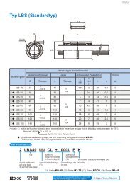
Dimensional Table<br />
<strong>Caged</strong> <strong>Ball</strong> <strong>LM</strong> <strong>Guide</strong> <br />
Model <strong>SPR</strong>-LR<br />
<br />
<br />
<br />
<br />
<br />
<br />
<br />
<br />
<br />
<br />
Model<br />
No.<br />
Outer dimensions<br />
<strong>LM</strong> block dimensions<br />
Height Width Length Mounting hole<br />
M W L B C C S L 1 T K N f o E e o D o<br />
Grease<br />
nipple<br />
<strong>SPR</strong>25LR 31 72 180.1 47 40 120 M810.5 158.1 10 26.5 6.3 9.2 12 4.5 3.9 B-M6F<br />
<strong>SPR</strong>30LR 38 90 207.8 58 45 135 M1014 182.6 12 33 8.0 10.9 12 4.5 3.9 B-M6F<br />
<strong>SPR</strong>35LR 44 100 235.5 66 50 150 M1216 208.3 14 38 9.5 12.4 12 6 5.2 B-M6F<br />
<strong>SPR</strong>45LR 52 120 288.5 78 65 195 M1418.5 256.5 16 44 10.5 12.3 16 6 5.2 B-PT1/8<br />
Model number coding <br />
Model number<br />
With QZ<br />
Lubricator<br />
No. of <strong>LM</strong> blocks<br />
used on the same<br />
rail<br />
Contamination<br />
protection<br />
accessory<br />
symbol<br />
(see page 16)<br />
<strong>LM</strong> rail length<br />
(in mm)<br />
Radial clearance<br />
symbol (see page 7)<br />
Symbol for No.<br />
of rails used on<br />
the same plane<br />
Type of <strong>LM</strong> block<br />
Accuracy symbol<br />
(see page 6)<br />
Note) This model number indicates that an <strong>LM</strong> block and an <strong>LM</strong> rail constitute one set (i.e., the required number of sets when 2 rails are used in parallel is 2).<br />
We recommend mounting the grease nipple in the standard position. If desiring to mount it on the side or in other positions, contact <strong>THK</strong>.
Unit: mm<br />
<strong>LM</strong> rail dimensions Basic load rating Static permissible moment [kN-m]* 3 Mass<br />
Width Height Pitch Mounting hole Length C C o<br />
M A M B M C <strong>LM</strong> block <strong>LM</strong> rail<br />
H 3<br />
W 1<br />
0<br />
-0.05<br />
W 2 M 1 F d 1d 2h Max* 2 [kN] [kN]<br />
1<br />
block Double<br />
blocks<br />
1<br />
block Double<br />
blocks<br />
1<br />
block<br />
4.5 35 18.5 18.2 40 91412 2680 59.9 156 3.22 14.5 1.69 7.59 1.72 1.5 4.1<br />
[kg]<br />
[kg/m]<br />
5 45 22.5 21.4 52.5 1117.514 3090 83.2 212 5.08 22.7 2.66 11.9 3.02 2.7 6.9<br />
6 50 25 25 52.5 142017 3090 111 278 7.56 33.6 3.96 17.6 4.37 4.0 9.0<br />
8 60 30 30.2 60 162320 3060 178 434 13.8 64.4 7.73 33.7 8.05 7.0 11.6<br />
*1 Pilot holes for side nipples are not drilled through in order to prevent foreign material from entering the product.<br />
<strong>THK</strong> will mount grease nipples per your request. Therefore, do not use the side nipple pilot holes for purposes other than mounting a grease nipple.<br />
*2 The maximum length under Length indicates the standard maximum length of an <strong>LM</strong> rail.<br />
*3 Static permissible moment: 1 block: static permissible moment value with 1 <strong>LM</strong> block<br />
Double blocks: static permissible moment value with 2 blocks closely contacting with each other<br />
*4 In case of oil lubrication, be sure to let <strong>THK</strong> know the mounting orientation and the exact position in each <strong>LM</strong> block where the piping joint should be attached.
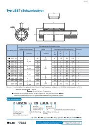
Dimensional Table<br />
<strong>Caged</strong> <strong>Ball</strong> <strong>LM</strong> <strong>Guide</strong> <br />
Model <strong>SPS</strong>-LR<br />
<br />
<br />
<br />
<br />
<br />
<br />
<br />
<br />
<br />
<br />
Outer dimensions<br />
<strong>LM</strong> block dimensions<br />
Model<br />
No.<br />
Height Width Length<br />
M W L B<br />
Mounting hole<br />
Pitch<br />
C<br />
C S L 1 T K N f o E e o D o<br />
Grease<br />
nipple<br />
<strong>SPS</strong>25LR 31 72 180.1 47 40 120 M810.5 158.1 10 26.5 6.3 9.2 12 4.5 3.9 B-M6F<br />
<strong>SPS</strong>30LR 38 90 207.8 58 45 135 M1014 182.6 12 33 8.0 10.9 12 4.5 3.9 B-M6F<br />
<strong>SPS</strong>35LR 44 100 235.5 66 50 150 M1216 208.3 14 38 9.5 12.4 12 6 5.2 B-M6F<br />
<strong>SPS</strong>45LR 52 120 288.5 78 65 195 M1418.5 256.5 16 44 10.5 12.3 16 6 5.2 B-PT1/8<br />
Model number coding <br />
Model number<br />
With QZ<br />
Lubricator<br />
No. of <strong>LM</strong> blocks<br />
used on the same<br />
rail<br />
Contamination<br />
protection<br />
accessory<br />
symbol<br />
(see page 16)<br />
<strong>LM</strong> rail length<br />
(in mm)<br />
Radial clearance<br />
symbol (see page 7)<br />
Symbol for No.<br />
of rails used on<br />
the same plane<br />
Type of <strong>LM</strong> block<br />
Accuracy symbol<br />
(see page 6)<br />
Note) This model number indicates that an <strong>LM</strong> block and an <strong>LM</strong> rail constitute one set (i.e., the required number of sets when 2 rails are used in parallel is 2).<br />
We recommend mounting the grease nipple in the standard position. If desiring to mount it on the side or in other positions, contact <strong>THK</strong>.
Unit: mm<br />
<strong>LM</strong> rail dimensions Basic load rating Static permissible moment [kN-m]* 3 Mass<br />
Width Height Pitch Mounting hole Length C C o<br />
M A M B M C <strong>LM</strong> block <strong>LM</strong> rail<br />
H 3<br />
W 1<br />
0<br />
-0.05<br />
W 2 M 1 F d 1d 2h Max* 2 [kN] [kN]<br />
1<br />
block Double<br />
blocks<br />
1<br />
block Double<br />
blocks<br />
1<br />
block<br />
4.5 35 18.5 18.2 40 91412 2680 42.4 110 2.91 13.1 2.91 13.1 1.38 1.5 4.1<br />
[kg]<br />
[kg/m]<br />
5 45 22.5 21.4 52.5 1117.514 3090 58.8 150 4.59 20.6 4.59 20.6 2.44 2.7 6.9<br />
6 50 25 25 52.5 142017 3090 78.2 196 6.83 30.4 6.83 30.4 3.52 4.0 9.0<br />
8 60 30 30.2 60 162320 3060 126 307 13.2 58.2 13.2 58.2 6.46 7.0 11.6<br />
*1 Pilot holes for side nipples are not drilled through in order to prevent foreign material from entering the product.<br />
<strong>THK</strong> will mount grease nipples per your request. Therefore, do not use the side nipple pilot holes for purposes other than mounting a grease nipple.<br />
*2 The maximum length under Length indicates the standard maximum length of an <strong>LM</strong> rail.<br />
*3 Static permissible moment: 1 block: static permissible moment value with 1 <strong>LM</strong> block<br />
Double blocks: static permissible moment value with 2 blocks closely contacting with each other<br />
*4 In case of oil lubrication, be sure to let <strong>THK</strong> know the mounting orientation and the exact position in each <strong>LM</strong> block where the piping joint should be attached.
Dimensional Table<br />
<strong>Caged</strong> <strong>Ball</strong> <strong>LM</strong> <strong>Guide</strong> <br />
Standard Length and Maximum Length of the <strong>LM</strong> Rail<br />
Table1 shows the standard <strong>LM</strong> rail lengths and the maximum lengths of models <strong>SPR</strong>/<strong>SPS</strong> variations.<br />
For the G dimension when a special length is required, we recommend selecting the corresponding G value from the table.<br />
The longer the G dimension is, the less stable the G area may become after installation, thus causing an adverse impact to<br />
accuracy.<br />
G F F<br />
G<br />
L0<br />
Standard Length and Maximum Length of the <strong>LM</strong> Rail for Models <strong>SPR</strong>/<strong>SPS</strong><br />
Unit: mm<br />
Model No. <strong>SPR</strong>/<strong>SPS</strong> 25 <strong>SPR</strong>/<strong>SPS</strong> 30 <strong>SPR</strong>/<strong>SPS</strong> 35 <strong>SPR</strong>/<strong>SPS</strong> 45<br />
280 570 570 780<br />
360 675 675 900<br />
440 780 780 1020<br />
520 885 885 1140<br />
600 990 990 1260<br />
680 1095 1095 1380<br />
760 1200 1200 1500<br />
840 1305 1305 1620<br />
920 1410 1410 1740<br />
1000 1515 1515 1860<br />
1080 1620 1620 1980<br />
1160 1725 1725 2100<br />
1240 1830 1830 2220<br />
<strong>LM</strong> rail standard length (L0)<br />
1320 1935 1935 2340<br />
1400 2040 2040 2460<br />
1480 2145 2145 2580<br />
1560 2250 2250 2700<br />
1640 2355 2355 2820<br />
1720 2460 2460 2940<br />
1800 2565 2565 3060<br />
1880 2670 2670<br />
1960 2775 2775<br />
2040 2880 2880<br />
2200 2985 2985<br />
2360 3090 3090<br />
2520<br />
2680<br />
Standard pitch F 40 52.5 52.5 60<br />
G 20 22.5 22.5 30<br />
Max length 2680 3090 3090 3060<br />
Note: If jointed rails are not allowed.
<strong>SPR</strong>/<strong>SPS</strong> OPTIONS<br />
Options<br />
For models <strong>SPR</strong>/<strong>SPS</strong>, contamination protection and lubrication accessories<br />
are available. Make a selection according to the application and the installation site.<br />
<br />
End Seal<br />
<br />
Double Seals<br />
<br />
<br />
Laminated Contact<br />
Scraper LaCS<br />
Metal Scraper<br />
(Non-contact)<br />
<br />
QZ Lubricator<br />
<br />
Inner Seal<br />
<br />
<br />
C/GC Caps exclusively<br />
for <strong>LM</strong> rail mounting holes<br />
*Requires special Rail<br />
<br />
Side Seal
Options<br />
<strong>Caged</strong> <strong>Ball</strong> <strong>LM</strong> <strong>Guide</strong> <br />
Contamination Protection Accessories<br />
When foreign material enters an <strong>LM</strong> system, it will cause abnormal wear or shorten the service life. It is necessary to prevent<br />
foreign material from entering the system. Therefore, when possible entrance of foreign material is predicted, it is important to<br />
select an effective sealing device or dust-prevention device that meets the working conditions.<br />
to Seals<br />
Side Seal<br />
Highly wear-resistant end seals made of special resin rubber<br />
and side seals for increased dust-prevention effect are<br />
available.<br />
Used in locations where dust may enter the <strong>LM</strong> block from the<br />
side or bottom surface, such as vertical, horizontal and<br />
inverted mounts<br />
If desiring a contamination protection accessory, specify it with the corresponding<br />
symbol indicated in table 3.<br />
For the supported <strong>LM</strong> <strong>Guide</strong> model numbers for contamination protection<br />
accessories and the overall <strong>LM</strong> block length with a contamination protection<br />
accessory attached (dimension L), see table 4.<br />
Seal resistance value<br />
For the maximum seal resistance value per <strong>LM</strong> block when a lubricant is applied<br />
on seal UU/SS, refer to the corresponding value provided in table 1.<br />
Side Seal<br />
Table 1 Maximum Seal Resistance Value of Seals <strong>SPR</strong>/<strong>SPS</strong> UU<br />
Unit: N<br />
Model No. Seal UU Seal SS<br />
<strong>SPR</strong>/<strong>SPS</strong>25 3 7<br />
<strong>SPR</strong>/<strong>SPS</strong>30 5 11<br />
<strong>SPR</strong>/<strong>SPS</strong>35 8 16<br />
<strong>SPR</strong>/<strong>SPS</strong>45 10 20<br />
<br />
Inner Seal<br />
Used in locations severely exposed to dust or cutting chips<br />
Inner Seal<br />
<br />
End Seal<br />
Used in locations exposed to dust<br />
<br />
Double Seals<br />
Used in locations exposed to much dust or many cutting<br />
chips<br />
End Seal<br />
End Seal
Scrapers<br />
Laminated Contact Scraper LaCS®<br />
For locations with an even more adverse working conditions,<br />
the Laminated Contact Scraper LaCS is available.<br />
LaCS removes minute foreign material adhering to the <strong>LM</strong><br />
rail in multiple stages and prevents it from entering the <strong>LM</strong><br />
block with a laminated contact structure (3-layer scraper).<br />
Features<br />
Since the 3 layers of scrapers fully contact the <strong>LM</strong> rail, LaCS is highly capable<br />
of removing minute foreign material.<br />
Since it uses oil-impregnated, foam synthetic rubber with a self-lubricating<br />
function, low friction resistance is achieved.<br />
Basic Specifi cations of LaCS<br />
Service temperature range of LaCS: -20°C to +80°C<br />
Resistance of LaCS (for Reference): indicated in table 2<br />
*Note that LaCS is not sold alone.<br />
Table 2 Resistance of LaCS<br />
Model No.<br />
Maximum resistance<br />
<strong>SPR</strong>/<strong>SPS</strong>25 13.0<br />
<strong>SPR</strong>/<strong>SPS</strong>30 20.2<br />
<strong>SPR</strong>/<strong>SPS</strong>35 22.9<br />
<strong>SPR</strong>/<strong>SPS</strong>45 27.4<br />
Unit: N<br />
Note 1: Each resistance value in the table only consists of that of LaCS, and does<br />
not include sliding resistances of seals and other accessories.<br />
Note 2: For the maximum service speed of LaCS, contact <strong>THK</strong>.<br />
<br />
<br />
LaCS<br />
Used in harsh environments exposed to foreign material such<br />
as fi ne dust and liquids.<br />
<strong>Ball</strong> cage<br />
<strong>Ball</strong><br />
Contact scraper<br />
Liquid<br />
Large amount of<br />
foreign material<br />
Metal Scraper (Non-contact)<br />
Used in locations where welding spatter may adhere to the <strong>LM</strong><br />
rail.<br />
Metal scraper<br />
Table 3<br />
Symbols of Contamination Protection Accessories for Models <strong>SPR</strong>/<strong>SPS</strong><br />
Symbol Contamination protection accessory<br />
UU With end seal<br />
SS With end seal + side seal + inner seal<br />
DD With double seals + side seal + inner seal<br />
ZZ With end seal + side seal + inner seal + metal scraper<br />
KK With double seals + side seal + inner seal + metal scraper<br />
SSHH With end seal + side seal + inner seal + LaCS<br />
DDHH With double seals + side seal + inner seal + LaCS<br />
ZZHH<br />
KKHH<br />
With end seal + side seal + inner seal + metal scraper + LaCS<br />
With double seals + side seal + inner seal + metal scraper + LaCS<br />
For the incremental dimension for mounting the grease nipple, contact <strong>THK</strong>.<br />
Table 4<br />
Overall <strong>LM</strong> Block Length (Dimension L) of Models <strong>SPR</strong>/<strong>SPS</strong> with a Contamination Protection Accessory Attached<br />
<br />
Model No. SSUU DD ZZ KK SSHH DDHH ZZHH KKHH<br />
<strong>SPR</strong>/<strong>SPS</strong>25 180.1 187.5 185.8 193.2 200.4 207.8 202.8 210.2<br />
<strong>SPR</strong>/<strong>SPS</strong>30 207.8 216.2 214.3 222.7 231.1 239.5 234.3 242.7<br />
<strong>SPR</strong>/<strong>SPS</strong>35 235.5 243.9 242 250.4 258.8 267.2 262 270.4<br />
<strong>SPR</strong>/<strong>SPS</strong>45 288.5 297.9 295 304.4 311.8 321.2 315 324.4
Options<br />
<strong>Caged</strong> <strong>Ball</strong> <strong>LM</strong> <strong>Guide</strong> <br />
Dedicated C-cap for <strong>LM</strong> Rail Mounting Holes<br />
If any of the <strong>LM</strong> rail mounting holes of an <strong>LM</strong> <strong>Guide</strong> is fi lled with<br />
cutting chips or foreign material, they may enter the <strong>LM</strong> block<br />
structure. Entrance of such foreign material can be prevented by<br />
covering each <strong>LM</strong> rail mounting hole with the dedicated cap.<br />
Since the dedicated cap C for <strong>LM</strong> rail mounting holes uses a special synthetic<br />
resin with high oil resistance and high wear resistance, it is highly durable.<br />
When placing an order, specify the respective cap C model number from the<br />
table below. The cap can also be made of other material (e.g., metal). For<br />
details, contact <strong>THK</strong>.<br />
Model No.<br />
Model No. Bolt Main dimensionsmm<br />
for C Cap used D H<br />
<strong>SPR</strong>/<strong>SPS</strong>25 C8 M8 14.4 3.7<br />
<strong>SPR</strong>/<strong>SPS</strong>30 C10 M10 18.0 3.7<br />
<strong>SPR</strong>/<strong>SPS</strong>35 C12 M12 20.5 4.7<br />
<strong>SPR</strong>/<strong>SPS</strong>45 C14 M14 23.5 5.7<br />
<br />
Dedicated C-cap for the <strong>LM</strong> rail mounting hole<br />
It prevents cutting chips from entering the <strong>LM</strong> rail mounting<br />
hole.<br />
H<br />
D<br />
Metal Cap Dedicated for <strong>LM</strong> Rail Mounting Holes GC Cap<br />
GC cap is a metallic cap that plugs the <strong>LM</strong> rail mounting hole (article<br />
compliant with the RoHS Directives). It prevents the entrance of<br />
foreign material and coolant from the <strong>LM</strong> rail top face (mounting hole)<br />
under harsh environments, and signifi cantly increases the dust control<br />
performance of the <strong>LM</strong> <strong>Guide</strong> if used with a dust control seal.<br />
<br />
Cap GC<br />
D<br />
Model No.<br />
Model No. Bolt Main dimensionsmm<br />
for GC Cap used D H<br />
<strong>SPR</strong>/<strong>SPS</strong>25 GC8 M8 14.36 3.5<br />
<strong>SPR</strong>/<strong>SPS</strong>30 GC10 M10 17.86 3.5<br />
<strong>SPR</strong>/<strong>SPS</strong>35 GC12 M12 20.36 4.6<br />
<strong>SPR</strong>/<strong>SPS</strong>45 GC14 M14 23.36 5.0<br />
H<br />
If designating an <strong>LM</strong> <strong>Guide</strong> model attached with GC cap, observe<br />
the following example of model number coding.<br />
Model number coding<br />
<br />
With GC cap<br />
* Add the symbol (GC) to the<br />
end of the model number.<br />
<br />
The procedure for inserting a GC cap into a mounting hole<br />
consists of using a fl at aligning fi tting to gradually punch the<br />
cap into the hole until it is level with the upper surface of the<br />
<strong>LM</strong> rail, as shown in the fi gure. Fit GC caps without removing<br />
the <strong>LM</strong> rail from the <strong>LM</strong> block.<br />
Note1) <strong>LM</strong> guides with GC caps are special rails.<br />
Note2) They cannot be mounted on stainless steel <strong>LM</strong> rails or <strong>LM</strong> rails that have<br />
undergone surface treatment.<br />
Note3) If this product will be used in special environments, such as in a vacuum or<br />
at very low or high temperatures, contact <strong>THK</strong>.<br />
Note4) GC caps are not sold individually. They are sold as a set with <strong>LM</strong> guides.<br />
Note5) The openings of <strong>LM</strong> rail mounting holes are not chamfered. Take care not to<br />
injure your hands while working.<br />
Note6) After fi tting GC caps, the upper surface of the <strong>LM</strong> rail must be fl attened and<br />
cleaned (wiped).<br />
Dedicated Bellows<br />
For details of the dedicated bellows, contact <strong>THK</strong>.<br />
GC Cap<br />
Plastic hammer<br />
Flat metal piece
Lubrication Accessories<br />
QZ Lubricator<br />
QZ Lubricator feeds the right amount of lubricant to the<br />
raceway on the <strong>LM</strong> rail. This allows an oil fi lm to continuously<br />
be formed between the rolling element and the raceway,<br />
and drastically extends the lubrication and maintenance<br />
intervals.<br />
When the QZ Lubricator is required, specify the desired type with the corresponding<br />
symbol indicated in table 5.<br />
For supported <strong>LM</strong> <strong>Guide</strong> model numbers for the QZ Lubricator and the overall block<br />
length with the QZ Lubricator attached (L dimension), see table 6.<br />
Features<br />
QZ Lubricator<br />
Case<br />
Heavily oil-impregnated fiber net<br />
<br />
High-density fiber net<br />
<strong>Ball</strong><br />
Since it supplements an oil loss, the lubrication maintenance interval can be<br />
significantly extended.<br />
Eco-friendly lubrication system that does not contaminate the surrounding<br />
area since it feeds the right amount of lubricant to the ball raceway.<br />
The user can select a type of lubricant that meets the intended use.<br />
Signifi cantly Extended Maintenance Interval<br />
Attaching QZ Lubricator helps extend the maintenance interval throughout the<br />
whole load range from the light load area to the heavy load area.<br />
*Note that the QZ Lubricator is not sold alone.<br />
Table 5<br />
Parts Symbols for Models <strong>SPR</strong>/<strong>SPS</strong> with the QZ Lubricator Attached<br />
Symbol Contamination protection accessories for <strong>LM</strong> <strong>Guide</strong> with QZ Lubricator attached<br />
QZUU With end seal + QZ Lubricator<br />
QZSS With end seal + side seal + inner seal + QZ Lubricator<br />
QZDD With double seals + side seal + inner seal + QZ Lubricator<br />
QZZZ With end seal + side seal + inner seal + metal scraper + QZ Lubricator<br />
QZKK With double seals + side seal + inner seal + metal scraper + QZ Lubricator<br />
QZSSHH With end seal + side seal + inner seal + LaCS + QZ Lubricator<br />
QZDDHH With double seals + side seal + inner seal + LaCS + QZ Lubricator<br />
QZZZHH With end seal + side seal + inner seal + metal scraper + LaCS + QZ Lubricator<br />
QZKKHH With double seals + side seal + inner seal + metal scraper + LaCS + QZ Lubricator<br />
For the incremental dimension for mounting the grease nipple, contact <strong>THK</strong>.<br />
Oil control plate<br />
Flow of lubricant <strong>Ball</strong> cage<br />
The structure of the QZ Lubricator consists<br />
of three major components:<br />
a heavy oil-impregnated fiber net (functions to store lubricant).<br />
a high-density fiber net (functions to apply lubricant to the raceway).<br />
an oil-control plate (functions to adjust oil flow).<br />
The lubricant contained in the QZ Lubricator is fed by the capillary<br />
phenomenon, which is used also in felt pens and many other products,<br />
as the fundamental principle.<br />
Table 6<br />
Overall <strong>LM</strong> Block Length (Dimension L) of Models <strong>SPR</strong>/<strong>SPS</strong> with the QZ Lubricator Attached<br />
<br />
Model No. QZUUSS QZDD QZZZ QZKK QZSSHH QZDDHH QZZZHH QZKKHH<br />
<strong>SPR</strong>/<strong>SPS</strong>25 202.1 209.5 207.8 215.2 222.4 229.8 224.8 232.2<br />
<strong>SPR</strong>/<strong>SPS</strong>30 229.8 238.2 236.3 244.7 253.1 261.5 256.3 264.7<br />
<strong>SPR</strong>/<strong>SPS</strong>35 267.5 275.9 274 282.4 290.8 299.2 294 302.4<br />
<strong>SPR</strong>/<strong>SPS</strong>45 320.5 329.9 327 336.4 343.8 353.2 347 356.4
<strong>Caged</strong> <strong>Ball</strong> <strong>LM</strong> <strong>Guide</strong> <strong>SPR</strong>/<strong>SPS</strong><br />
Precautions on use<br />
Handling<br />
· This product consists mostly of heavy items (20 kg or more). When moving heavy items, use 2 or more people or moving equipment. This<br />
could cause injury or product damage.<br />
· Do not disassemble the parts. This will cause dust to enter the product resulting in loss of functionality.<br />
· Tilting an <strong>LM</strong> block or <strong>LM</strong> rail may cause them to fall by their own weight.<br />
· Take care not to drop or strike the <strong>LM</strong> guide. This could cause injury or product damage. Giving an impact to it could also cause damage to its<br />
function even if the product looks intact.<br />
· Prevent foreign material, such as dust or cutting chips, from entering the system. This could cause damage to ball circulation components and<br />
loss of functionality.<br />
· When planning to use the <strong>LM</strong> system in an environment where the coolant penetrates the <strong>LM</strong> block, it may cause trouble to product functions<br />
depending on the type of the coolant. Contact <strong>THK</strong> for details.<br />
· Do not use the product at temperature of 80 or higher. Contact <strong>THK</strong> if you desire to use the product at a temperature of 80 or higher.<br />
· If foreign material such as dust or cutting chips adheres to the product, replenish the lubricant after cleaning the product with pure white<br />
kerosene. For available types of detergent, contact <strong>THK</strong>.<br />
· If an <strong>LM</strong> guide will be in an inverted orientation, take preventive measures such as adding a safety mechanism to prevent falls. If the end plate<br />
is damaged due to an accident, etc., balls may fall out of the guide or the <strong>LM</strong> block become detached from the <strong>LM</strong> rail and fall down.<br />
· When using the product in locations exposed to constant vibrations or in special environments such as clean rooms, vacuum and low/high<br />
temperature, contact <strong>THK</strong> in advance.<br />
· When removing the <strong>LM</strong> block from the <strong>LM</strong> rail and then replacing the block, an <strong>LM</strong> block mounting/ removing jig that facilitates such<br />
installation is available. Contact <strong>THK</strong> for details.<br />
· When installing the <strong>LM</strong> <strong>Guide</strong>, be sure not to remove the <strong>LM</strong> block from the <strong>LM</strong> rail to the extent possible. If removing and reattaching the <strong>LM</strong><br />
block is inevitable, contact <strong>THK</strong>.<br />
Lubrication<br />
· Thoroughly remove anti-rust oil and feed lubricant before using the product.<br />
· Do not mix lubricants of different physical properties.<br />
· In locations exposed to constant vibrations or in special environments such as clean rooms, vacuum and low/high temperature, normal<br />
lubricants may not be used. Contact <strong>THK</strong> for details.<br />
· When planning to use a special lubricant, contact <strong>THK</strong> before using it.<br />
· When adopting oil lubrication, the lubricant may not be distributed throughout the <strong>LM</strong> system depending on the mounting orientation of the<br />
system. Contact <strong>THK</strong> for details.<br />
· Lubrication interval varies according to the conditions. Contact <strong>THK</strong> for details.<br />
Storage<br />
When storing the <strong>LM</strong> <strong>Guide</strong>, enclose it in a package designated by <strong>THK</strong> and store it in a horizontal<br />
orientation while avoiding high temperature, low temperature and high humidity.<br />
“<strong>LM</strong> GUIDE,” and “ ” are registered trademarks of <strong>THK</strong> CO., LTD.<br />
●The photo may differ slightly in appearance from the actual product.<br />
●The appearance and specifications of the product are subject to change without notice. Contact <strong>THK</strong> before placing an order.<br />
●Although great care has been taken in the production of this catalog, <strong>THK</strong> will not take any responsibility for damage resulting from typographical errors or omissions.<br />
●For the export of our products or technologies and for the sale for exports, <strong>THK</strong> in principle complies with the foreign exchange law and the Foreign Exchange and<br />
Foreign Trade Control Law as well as other relevant laws.<br />
For export of <strong>THK</strong> products as single items, contact <strong>THK</strong> in advance.<br />
All rights reserved<br />
NORTH AMERICA<br />
<strong>THK</strong> America,Inc.<br />
HEADQUARTERS<br />
Phone:+1-847-310-1111<br />
CHICAGO OFFICE<br />
Phone:+1-847-310-1111<br />
NORTH EAST OFFICE<br />
Phone:+1-845-369-4035<br />
ATLANTA OFFICE<br />
Phone:+1-770-840-7990<br />
LOS ANGELES OFFICE<br />
Phone:+1-949-955-3145<br />
SAN FRANCISCO OFFICE<br />
Phone:+1-925-455-8948<br />
DETROIT OFFICE<br />
Phone:+1-248-858-9330<br />
TORONTO OFFICE<br />
Phone:+1-905-820-7800<br />
SOUTH AMERICA<br />
<strong>THK</strong> BRAZIL INDUSTRIA E COMERCIO LTDA.<br />
Phone:+55-11-3767-0100 Fax:+55-11-3767-0101<br />
EUROPE<br />
<strong>THK</strong> GmbH<br />
EUROPEAN HEADQUARTERS<br />
Phone:+49-2102-7425-555 Fax:+49-2102-7425-556<br />
DÜSSELDORF OFFICE<br />
Phone:+49-2102-7425-0 Fax:+49-2102-7425-299<br />
STUTTGART OFFICE<br />
Phone:+49-7141-4988-500 Fax:+49-7141-4988-888<br />
U.K. OFFICE<br />
Phone:+44-1384-47-1550 Fax:+44-1384-47-1551<br />
HEAD OFFICE 3-11-6, NISHI-GOTANDA, SHINAGAWA-KU, TOKYO 141-8503 JAPAN<br />
INTERNATIONAL SALES DEPARTMENT PHONE:+81-3-5434-0351 FAX:+81-3-5434-0353<br />
Global site : http://www.thk.com/<br />
ITALY OFFICE<br />
GUANGZHOU OFFICE<br />
Phone:+39-02-99011801 Fax:+39-02-99011881 Phone:+86-20-8523-8418 Fax:+86-20-3801-0456<br />
SWEDEN OFFICE<br />
SHENZHEN OFFICE<br />
Fax:+1-847-310-1271 Phone:+46-8-445-7630 Fax:+46-8-445-7639<br />
Phone:+86-755-2642-9587 Fax:+86-755-2642-9604<br />
AUSTRIA OFFICE<br />
XIAN OFFICE<br />
Fax:+1-847-310-1182 Phone:+43-7229-51400 Fax:+43-7229-51400-79 Phone:+86-29-8834-1712 Fax:+86-29-8834-1710<br />
SPAIN OFFICE<br />
<strong>THK</strong> (SHANGHAI) CO.,LTD.<br />
Fax:+1-845-369-4909 Phone:+34-93-652-5740 Fax:+34-93-652-5746 Phone:+86-21-6275-5280 Fax:+86-21-6219-9890<br />
Fax:+1-770-840-7897<br />
TURKEY OFFICE<br />
TAIWAN<br />
Phone:+90-216-362-4050 Fax:+90-216-569-7150 <strong>THK</strong> TAIWAN CO.,LTD.<br />
Fax:+1-949-955-3149<br />
Fax:+1-925-455-8965<br />
Fax:+1-248-858-9455<br />
PRAGUE OFFICE<br />
Phone:+420-2-41025-100<br />
MOSCOW OFFICE<br />
Phone:+7-495-649-80-47<br />
<strong>THK</strong> Europe B.V.<br />
EINDHOVEN OFFICE<br />
Fax:+420-2-41025-199<br />
Fax:+7-495-649-80-44<br />
TAIPEI HEAD OFFICE<br />
Phone:+886-2-2888-3818<br />
TAICHUNG OFFICE<br />
Phone:+886-4-2359-1505<br />
TAINAN OFFICE<br />
Phone:+886-6-289-7668<br />
Fax:+886-2-2888-3819<br />
Fax:+886-4-2359-1506<br />
Fax:+886-6-289-7669<br />
Fax:+1-905-820-7811<br />
Phone:+31-040-290-9500 Fax:+31-040-290-9599 KOREA<br />
<strong>THK</strong> France S.A.S.<br />
SEOUL REPRESENTATIVE OFFICE<br />
Phone:+33-4-3749-1400 Fax:+33-4-3749-1401<br />
CHINA<br />
<strong>THK</strong> (CHINA) CO.,LTD.<br />
HEADQUARTERS<br />
Phone:+86-411-8733-7111 Fax:+86-411-8733-7000<br />
SHANGHAI OFFICE<br />
Phone:+86-21-6219-3000 Fax:+86-21-6219-9890<br />
BEIJING OFFICE<br />
Phone:+86-10-8441-7277 Fax:+86-10-6590-3557<br />
CHENGDU OFFICE<br />
Phone:+86-28-8526-8025 Fax:+86-28-8525-6357<br />
Phone:+82-2-3468-4351 Fax:+82-2-3468-4353<br />
SINGAPORE<br />
<strong>THK</strong> <strong>LM</strong> SYSTEM Pte. Ltd.<br />
Phone:+65-6884-5500 Fax:+65-6884-5550<br />
THAILAND<br />
<strong>THK</strong> <strong>LM</strong> System Pte.Ltd.Representative Office in Thailand<br />
Phone:+660-2751-3001 Fax:+660-2751-3003<br />
INDIA<br />
BANGALORE REPRESENTATIVE OFFICE<br />
Phone:+91-80-2330-1524 Fax:+91-80-2330-1524<br />
©<strong>THK</strong> CO., LTD.<br />
201208020 E18 Printed in Japan