Direct Comparison of an Engine Working under Otto, Miller and ...
Direct Comparison of an Engine Working under Otto, Miller and ...
Direct Comparison of an Engine Working under Otto, Miller and ...

Create successful ePaper yourself
Turn your PDF publications into a flip-book with our unique Google optimized e-Paper software.
2007-01-0261<br />
<strong>Direct</strong> <strong>Comparison</strong> <strong>of</strong> <strong>an</strong> <strong>Engine</strong> <strong>Working</strong> <strong>under</strong> <strong>Otto</strong>, <strong>Miller</strong><br />
<strong>an</strong>d Diesel cycles: Thermodynamic Analysis <strong>an</strong>d Real <strong>Engine</strong><br />
Perform<strong>an</strong>ce<br />
Copyright © 2006 SAE International<br />
Bernardo RIBEIRO, Jorge MARTINS<br />
Dep. Eng. Mecânica, Universidade do Minho, Portugal<br />
ABSTRACT<br />
One <strong>of</strong> the ways to improve thermodynamic efficiency <strong>of</strong><br />
Spark Ignition engines is by the optimisation <strong>of</strong> valve<br />
timing <strong>an</strong>d lift <strong>an</strong>d compression ratio. The throttleless<br />
engine <strong>an</strong>d the <strong>Miller</strong> cycle engine are proven concepts<br />
for efficiency improvements <strong>of</strong> such engines.<br />
This paper reports on <strong>an</strong> engine with variable valve<br />
timing (VVT) <strong>an</strong>d variable compression ratio (VCR) in<br />
order to fulfill such <strong>an</strong> enh<strong>an</strong>cement <strong>of</strong> efficiency. <strong>Engine</strong><br />
load is controlled by the valve opening period (enabling<br />
throttleless operation <strong>an</strong>d <strong>Miller</strong> cycle), while the variable<br />
compression ratio keeps the efficiency high throughout<br />
all speed <strong>an</strong>d load conditions.<br />
A computer model is used to simulate such <strong>an</strong> engine<br />
<strong>an</strong>d evaluate its improvement potential, while a single<br />
cylinder engine demonstrates these results.<br />
The same base engine was run on the test bench <strong>under</strong><br />
the Diesel cycle, <strong>Otto</strong> cycle <strong>an</strong>d <strong>Miller</strong> cycle conditions,<br />
enabling direct thermodynamic comparisons <strong>under</strong> a<br />
wide variety <strong>of</strong> conditions <strong>of</strong> speed <strong>an</strong>d load.<br />
The results show a signific<strong>an</strong>t improvement <strong>of</strong> the <strong>Miller</strong><br />
cycle over the <strong>Otto</strong> cycle engine. <strong>Comparison</strong>s <strong>of</strong> the<br />
<strong>Miller</strong> engine with the Diesel engine shown that it is<br />
possible to have a SI engine with better efficiency th<strong>an</strong> a<br />
similar Diesel engine for most <strong>of</strong> the working conditions.<br />
INTRODUCTION<br />
<strong>Engine</strong> research for automotive purposes focuses its<br />
action on solving problems related to energy use <strong>an</strong>d<br />
pollution. Analyzing how energy is spent in car engines<br />
shows that the conventional <strong>Otto</strong> cycle engine is used<br />
with reduced efficiency for a signific<strong>an</strong>t part <strong>of</strong> the driving<br />
time. During most <strong>of</strong> the time the engine works at part<br />
load with low efficiency, decreasing even more as the<br />
load is further reduced [1,2]. Usually, engines are<br />
designed to have the best perform<strong>an</strong>ce at a certain<br />
working conditions. When they are operated at different<br />
conditions the perform<strong>an</strong>ce is poorer. Variable<br />
configuration engines must be used to improve<br />
efficiency throughout the working r<strong>an</strong>ge <strong>of</strong> the engine.<br />
Variation <strong>of</strong> valve timing <strong>an</strong>d lift <strong>an</strong>d compression ratio<br />
are signific<strong>an</strong>t parameters that c<strong>an</strong> contribute to engine<br />
perform<strong>an</strong>ce improvement.<br />
Valve event variation is one <strong>of</strong> the research fields more<br />
exploited in engine technology. Several variable valve<br />
actuating systems have been proposed [3-5] <strong>an</strong>d results<br />
reported. The variation <strong>of</strong> the intake valve closure timing<br />
on itself c<strong>an</strong> produce variations <strong>of</strong> the amount <strong>of</strong> air/fuel<br />
mixture trapped within the cylinder in each engine cycle.<br />
The substitution <strong>of</strong> the throttle valve, which is one <strong>of</strong> the<br />
main causes <strong>of</strong> the reduced cycle efficiency at reduced<br />
loads, by a variable valve timing (VVT) system for load<br />
control has been presented widely [6,7], with favorable<br />
results.<br />
The thermal efficiency <strong>of</strong> <strong>Otto</strong> cycle is theoretically<br />
expressed as:<br />
1<br />
η = 1 −<br />
(1)<br />
γ −1<br />
ε<br />
It c<strong>an</strong> be seen from (1) that, at least theoretically, the<br />
main variable that influences the thermal efficiency is the<br />
compression ratio. Its increase is a benefit for the<br />
thermodynamic perform<strong>an</strong>ce <strong>of</strong> the engine, but a limit is<br />
imposed by engine knock. If compression ratio could be<br />
adjusted to the cycle conditions, setting it to the<br />
maximum value before knock occurrence, signific<strong>an</strong>t<br />
improvement would be achieved. Several systems for<br />
compression ratio variation were reported <strong>an</strong>d<br />
implemented [8-11], <strong>an</strong>d benefits were qu<strong>an</strong>tified.<br />
In a previous work [2] this team developed a computer<br />
model to predict engine improvements using VVT <strong>an</strong>d<br />
variable compression ratio (VCR) simult<strong>an</strong>eously. Then<br />
a single cylinder engine was modified to work <strong>under</strong><br />
these conditions <strong>an</strong>d tests were conducted. In order to<br />
produce different compression ratios several pistons<br />
were used enabling results similar to a variable<br />
compression ratio engine. Also, different camshafts were
used to perform intake valve timing variation similar to a<br />
VVT engine.<br />
COMPUTER MODEL<br />
A computer model was used to simulate the engine<br />
perform<strong>an</strong>ce <strong>an</strong>d preview some preliminary results <strong>of</strong><br />
the perform<strong>an</strong>ce with different cam shapes <strong>an</strong>d different<br />
compression ratios. The program presented elsewhere<br />
[12], is a one zone model, with the combustion following<br />
a Wiebe function. It includes Ann<strong>an</strong>d heat tr<strong>an</strong>sfer<br />
coefficient [13], where average const<strong>an</strong>t temperatures<br />
are considered for the cylinder head, cylinder walls <strong>an</strong>d<br />
piston head. It includes a model for friction mep<br />
calculation [14,15]. Mass flow entering <strong>an</strong>d leaving the<br />
cylinder is simulated using a compressible flow model<br />
[16]. The model also considers variable gas properties<br />
as a function <strong>of</strong> in-cylinder temperature [17,18].<br />
The model calculates inst<strong>an</strong>t cylinder pressure <strong>an</strong>d<br />
temperature, from which it is capable <strong>of</strong> calculating<br />
several engine perform<strong>an</strong>ce parameters, like power<br />
(work), thermal efficiency, specific fuel consumption,<br />
indicated <strong>an</strong>d break me<strong>an</strong> effective pressure. The model<br />
includes the calculation <strong>of</strong> engine friction, so bmep c<strong>an</strong><br />
be calculated.<br />
For the simulations <strong>an</strong> engine configuration was set,<br />
similar to the real engine on the test bench. The engine<br />
characteristics are shown in table 1 for the <strong>Otto</strong> engine.<br />
In the real engine the combustion chamber has a deep<br />
toroidal bowl combustion chamber shape, while in the<br />
computer model a simplification was introduced <strong>an</strong>d a<br />
cylindrical combustion chamber shape was used.<br />
Table 1: <strong>Engine</strong> configuration data.<br />
Number <strong>of</strong> cylinders 1<br />
Bore [mm] 70<br />
Stroke [mm] 55<br />
Connecting rod length [mm] 90<br />
Combustion chamber height [mm] 5.3<br />
Total displacement [cc] 211<br />
Compression Ratio 11.5<br />
Intake Valve Diameter [mm] 30<br />
Exhaust Valve Diameter [mm] 25<br />
IVO [CA]<br />
20 BTDC<br />
IVC [CA]<br />
32 ABDC<br />
EVO [CA]<br />
40 BBDC<br />
EVC [CA]<br />
12 ATDC<br />
COMPUTATION RESULTS<br />
The preliminary computational simulations were made<br />
considering the following assumptions:<br />
Combustion starts at 20 BTDC at takes 40 CA to finish<br />
<strong>an</strong>d is considered as a complete <strong>an</strong>d stoichiometric<br />
combustion. Gasoline was the fuel selected for the<br />
performed simulations.<br />
Temperatures from the cylinder walls are considered<br />
const<strong>an</strong>t during all the cycle.<br />
For the <strong>Otto</strong> cycle at WOT the maximum temperature <strong>of</strong><br />
the cycle is 2082 K <strong>an</strong>d peak pressure is 75 bar. This<br />
temperature <strong>an</strong>d pressure was used as a reference for<br />
the compression ratio adjustment when intake valve<br />
closure (IVC) time was ch<strong>an</strong>ged. As presented in<br />
<strong>an</strong>other work [1] if only the intake valve closing time<br />
ch<strong>an</strong>ged, <strong>an</strong> increase <strong>of</strong> the efficiency is expected in<br />
relation to the <strong>Otto</strong> cycle, but the efficiency still<br />
decreases with load reduction. If compression ratio is<br />
adjusted then <strong>an</strong> improvement is possible in terms <strong>of</strong><br />
thermal efficiency with the decrease <strong>of</strong> load, which is the<br />
main aim <strong>of</strong> this research.<br />
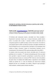
Figure 1 shows the specific fuel consumption versus<br />
engine load for the three SI engine versions: <strong>Otto</strong>, <strong>Miller</strong><br />
<strong>an</strong>d <strong>Miller</strong> VCR. It c<strong>an</strong> be seen that there is <strong>an</strong><br />
improvement just by the use <strong>of</strong> a variable valve timing<br />
system to control the load via late intake valve closure<br />
(Late IVC). When compression ratio adjustment is used,<br />
the benefit in terms <strong>of</strong> specific fuel consumption<br />
becomes much more import<strong>an</strong>t. It is relev<strong>an</strong>t to refer that<br />
with the <strong>Miller</strong> VCR engine the specific fuel consumption<br />
decreases as load is reduced from full throttle down to<br />
approximately 7 bar bmep, from 249 g/kWh down to<br />
237 g/kWh.<br />
sfc [g/kWh]<br />
400<br />
380<br />
360<br />
340<br />
320<br />
300<br />
280<br />
260<br />
240<br />
220<br />
<strong>Miller</strong><br />
<strong>Otto</strong> part load<br />
<strong>Miller</strong> with VCR<br />
200<br />
1 2 3 4 5 6 7 8 9 10 11<br />
bmep [bar]<br />
<strong>Otto</strong><br />
<strong>Miller</strong> LIVC<br />
<strong>Miller</strong> EIVC<br />
<strong>Miller</strong> VCR LIVC<br />
<strong>Miller</strong> VCR EIVC<br />
Baseline<br />
engine WOT<br />
Figure 1 – Specific fuel consumption as a function <strong>of</strong> load for 2500 rpm<br />
simulations.<br />
At very low loads or at idle, the compression ratio<br />
required to keep the <strong>Miller</strong> VCR engine strategy working
might be so high that it becomes physically impossible to<br />
realize it, because there is no space between piston <strong>an</strong>d<br />
poppet valves. In the case <strong>of</strong> idle the use <strong>of</strong> the throttle<br />
valve may be required when the Late IVC strategy is<br />
used, as the delay required to the intake valve to close is<br />
so high that the ignition would occur with the intake<br />
valve still open [3].<br />
In the case <strong>of</strong> Late IVC the minimum load presented in<br />
figure 1 is close to the minimum possible due to the<br />
referred problem <strong>of</strong> ignition during open intake valve. If<br />
early intake valve closure (Early IVC) is used for load<br />
control it is possible to achieve much lower loads.<br />
The engine, either working as simple <strong>Miller</strong> or as <strong>Miller</strong><br />
with VCR has better efficiency if Early IVC is used<br />
instead <strong>of</strong> Late IVC. This is mainly caused by reduced<br />
pumping losses. In the case <strong>of</strong> Late IVC the air/fuel<br />
mixture in inducted into the cylinder <strong>an</strong>d after the BDC it<br />
is blown-back again to the intake m<strong>an</strong>ifold. This effect is<br />
more intense as longer IVC delays are used.<br />
ENGINE MODIFICATION<br />
To perform a direct comparison between a Diesel engine<br />
<strong>an</strong>d a SI engine it was decided to use a Diesel engine<br />
<strong>an</strong>d after measuring its perform<strong>an</strong>ce, modify it to work<br />
as a spark ignition engine. With this modification the<br />
engine is capable to work as a SI engine, but several<br />
design characteristics are still optimized to work <strong>under</strong><br />
the Diesel.<br />
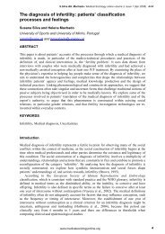
The Diesel engine used was a Y<strong>an</strong>mar L48 AE (figure<br />
2). The commercial Diesel engine specifications are<br />
presented in table 2.<br />
intake m<strong>an</strong>ifold with a throttle body was placed upstream<br />
<strong>of</strong> the intake duct. The intake m<strong>an</strong>ifold also included a<br />
fuel injector positioned upstream <strong>of</strong> the intake valve. The<br />
intake m<strong>an</strong>ifold volume was sized large enough to avoid<br />
fuel loss during the blow-back when using the Late IVC<br />
strategy. The first piston was modified to have a wide<br />
combustion chamber <strong>an</strong>d a compression ratio <strong>of</strong> 11.5:1.<br />
An electronic control unit was used to control spark<br />
timing <strong>an</strong>d fuel injection <strong>an</strong>d a pressurized fuel circuit<br />
was connected to the low pressure petrol injection. An<br />
ignition coil <strong>an</strong>d <strong>an</strong> ignition module were necessary for<br />
the ignition system operation.<br />
Table 2: Y<strong>an</strong>mar engine commercial specifications.<br />
Model<br />
L48AE<br />
Type<br />
Single-cylinder, vertical 4-<br />
cycle diesel<br />
Combustion system <strong>Direct</strong> injection<br />
Displacement [cc] 211<br />
<strong>Engine</strong> speed [rpm] 3000 3600<br />
Maximum output [hp] 4.2 4.7<br />
Continuous output [hp] 3.8 4.2<br />
Cooling<br />
Forced air<br />
Lubrication<br />
Oil pressure<br />
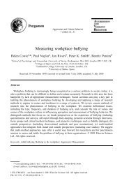
The first attempt to run the engine in SI mode was not<br />
completely successful due to the excessive swirl<br />
generated by the original (Diesel) intake duct in the<br />
engine head. The engine run without burning all the fuel,<br />
emitting large qu<strong>an</strong>tities <strong>of</strong> HC. As it c<strong>an</strong> be observed in<br />
the spark plug (figure 3), the burning zone was only on<br />
one side <strong>of</strong> the spark plug showing the direction <strong>of</strong> the<br />
extremely high swirl movement inside the cylinder.<br />
Swirl<br />
direction<br />
Figure 2: Y<strong>an</strong>mar engine on the test bench.<br />
Unburned<br />
side<br />
Figure 3: Burning zones on the spark plug, after first running attempt.<br />
In order to use the same DI Diesel engine as a SI engine<br />
several modifications were made. At the engine head<br />
the direct injection fuel injector was removed <strong>an</strong>d a<br />
spark plug was placed at the same position. A long<br />
So the engine head was mounted on a visualization rig,<br />
described in figure 4, to enable the study <strong>of</strong> the
generated swirl within the engine cylinder. Attached to<br />
the head was a glass tube with the diameter <strong>of</strong> the<br />
engine cylinder, but much longer. It was possible to<br />
notice the helix forming by the inlet air, when injecting<br />
smoke within the air stream. A paddle wheel was also<br />
used to measure the swirl index, by measuring the<br />
rotational speed at several dist<strong>an</strong>ces from the engine<br />
head (56 mm, 76 mm, 96 mm).<br />
engine<br />
head<br />
air inlet<br />
inlet<br />
valve<br />
glass<br />
cylinder<br />
air path<br />
Csp<br />
Csp<br />
Csp<br />
1000<br />
500<br />
1500<br />
1000<br />
500<br />
1500<br />
1000<br />
96 mm<br />
0<br />
0.002 0.003 0.004 0.005 0.006 0.007 0.008 0.009 0.01<br />
76 mm<br />
Original<br />
Modification<br />
0<br />
0.002 0.003 0.004 0.005 0.006 0.007 0.008 0.009 0.01<br />
500<br />
56 mm<br />
0<br />
0.002 0.003 0.004 0.005 0.006 0.007 0.008 0.009 0.01<br />
Flow [m3/s]<br />
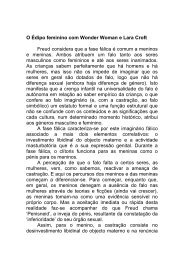
Figure 5: Swirl results after <strong>an</strong>d before the intake duct modification.<br />
paddle<br />
wheel<br />
0.4<br />
0.38<br />
0.36<br />
0.34<br />
Original<br />
Modification<br />
0.32<br />
Cd<br />
0.3<br />
0.28<br />
0.26<br />
0.24<br />
Figure 4: Testing rig for swirl measurement.<br />
0.22<br />
0.2<br />
0.001 0.002 0.003 0.004 0.005 0.006 0.007 0.008 0.009 0.01<br />
Flow [m3/s]<br />
The swirl reduction was achieved by me<strong>an</strong>s <strong>of</strong> intake<br />
duct modification. The original shape had a ch<strong>an</strong>nel for<br />
swirl induction in the air flow <strong>an</strong>d a deflector at the<br />
ch<strong>an</strong>nel end. The first modification made to the intake<br />
port was to create a deflector in the opposite side <strong>of</strong> the<br />
existing one. The existing deflector was eliminated <strong>an</strong>d<br />
the added deflector was built in such a way that it<br />
interrupted the air flow at the entr<strong>an</strong>ce <strong>of</strong> the swirl induct<br />
ch<strong>an</strong>nel. This ch<strong>an</strong>nel was also filled in order to reduce<br />
swirl movement <strong>of</strong> the incoming air. As described above<br />
the swirl was measured at several dist<strong>an</strong>ces from the<br />
engine head <strong>an</strong>d the results are presented in Figure 5.<br />
Swirl index was calculated using the definition <strong>of</strong> Ann<strong>an</strong>d<br />
<strong>an</strong>d Roe [19]. The reduction <strong>of</strong> the swirl, depending <strong>of</strong><br />
the dist<strong>an</strong>ce at which it is measured <strong>an</strong>d the air flow,<br />
goes from 60% up to 80%.<br />
The discharge coefficient <strong>of</strong> the induction port ch<strong>an</strong>ged<br />
<strong>an</strong>d the modification <strong>of</strong> the intake port was optimized in<br />
order to minimize the increase <strong>of</strong> the pressure drop in<br />
that passage. In fact the discharge coefficient increased<br />
slightly but the difference is acceptable for the case <strong>of</strong><br />
<strong>an</strong> intake port. Figure 6 shows the discharge coefficient<br />
with <strong>an</strong>d without the modification <strong>an</strong>d its evolution as a<br />
function <strong>of</strong> the air mass flow.<br />
Figure 6: Original <strong>an</strong>d modified discharge coefficient <strong>of</strong> the intake duct<br />
<strong>an</strong>d valve.<br />
ENGINE TESTS<br />
The different cams that were used in the engine had<br />
either Late IVC with different dwell <strong>an</strong>gles or Early IVC<br />
with different opening periods. The Late IVC cams had<br />
dwell <strong>an</strong>gles <strong>of</strong> 20, 40, 60 CA. Two Early IVC cams were<br />
tested to evaluate <strong>an</strong>d compare the ability <strong>of</strong> each load<br />
control strategy to reduce the engine load, as shown in<br />
figure 7.<br />
The exhaust timing <strong>an</strong>d the intake valve opening<br />
position was kept always the same. Figure 7 shows the<br />
lift <strong>of</strong> the valves during the cycle completion for the<br />
different camshafts used to achieve different loads.<br />
Figure 8 presents the volumetric efficiency <strong>of</strong> each<br />
camshaft, calculated with the test results performed at<br />
stoichiometric conditions. As it c<strong>an</strong> be seen the Early<br />
IVC strategy allowed much lower loads th<strong>an</strong> Late IVC.
To achieve the variation <strong>of</strong> the compression ratio,<br />
different pistons were used. As the original engine is a<br />
DI Diesel engine, the original pistons were used, <strong>an</strong>d the<br />
piston bowl <strong>of</strong> st<strong>an</strong>dard Diesel piston was enlarged to<br />
create different combustion chamber volume <strong>an</strong>d<br />
therefore different compression ratio. Table 3 reports the<br />
piston sizes <strong>an</strong>d compression ratios, including the<br />
original Diesel engine piston. The original configuration<br />
<strong>of</strong> the engine, as a Diesel, had a compression ratio <strong>of</strong><br />
19.9:1. The piston had a deep toroidal bowl combustion<br />
chamber. With this kind <strong>of</strong> design it is possible to<br />
enlarge the combustion chamber in the piston to a<br />
cylindrical bowl chamber (Figure 9). This combustion<br />
chamber shape is not the ideal for SI engines, but this<br />
was the possible chamber to be m<strong>an</strong>ufactured from the<br />
original combustion chamber (Diesel) <strong>of</strong> the engine.<br />
Figure 10 shows the several pistons used in the SI<br />
engine tests, from the <strong>Otto</strong> engine piston with a<br />
compression ratio <strong>of</strong> 11.5:1 up to a 17.5:1. Also, for<br />
comparison, the st<strong>an</strong>dard Diesel piston with a<br />
compression ratio <strong>of</strong> 19.9:1 is included.<br />
Table 3: Pistons specifications.<br />
Pisto<br />
n<br />
Combustion chamber<br />
diameter [mm]<br />
1 48.4 11.5:1<br />
2 46.0 12.5:1<br />
3 43.8 13.5:1<br />
4 41.8 14.5:1<br />
5 40.1 15.5:1<br />
6 38.5 16.5:1<br />
7 37.1 17.5:1<br />
Diese<br />
l<br />
original<br />
bowl<br />
CR=19.9:1<br />
Compression<br />
Ratio<br />
- 19.9:1<br />
CR=17.5:1<br />
CR=16.5:1<br />
CR=15.5:1<br />
CR=14.5:1<br />
CR=13.5:1<br />
CR=12.5:1<br />
CR=11.5:1<br />
7<br />
6<br />
60º<br />
40º<br />
Figure 9: Original <strong>an</strong>d modified combustion chambers.<br />
5<br />
20º<br />
Came Lift [mm]<br />
4<br />
3<br />
2<br />
EIVC<br />
LIVC<br />
19.9:1 17.5:1 16.5:1 15.5:1<br />
1<br />
0<br />
-360 -300 -240 -180 -120 -60 0 60 120 180 240 300 360<br />
Cr<strong>an</strong>k Angle [º]<br />
Figure 7 – Different cam pr<strong>of</strong>iles tested.<br />
14.5:1<br />
13.5:1<br />
12.5:1<br />
11.5:1<br />
Volumetric Efficiency [%]<br />
100<br />
LIVC1<br />
90<br />
<strong>Otto</strong> - WOT<br />
EIVC1<br />
80<br />
LIVC2<br />
70<br />
LIVC3<br />
60<br />
50<br />
EIVC2<br />
40<br />
30<br />
20<br />
10<br />
0<br />
1000 1500 2000 2500 3000 3500 4000<br />
[RPM]<br />
Figure 8: Volumetric efficiency <strong>of</strong> each camshaft.<br />
Figure 10: Pistons used in tests.<br />
TEST RESULTS<br />
Initial tests were made [20] with the engine in its<br />
commercial (st<strong>an</strong>dard) Diesel version, so that the results<br />
could be used as a baseline for comparison <strong>an</strong>d<br />
evaluation <strong>of</strong> improvements. The measured Diesel<br />
engine specific consumption map is shown in figure 11.<br />
After the engine conversion <strong>an</strong>d preliminary tests, the<br />
<strong>Otto</strong> engine version was completely mapped from 10%<br />
<strong>of</strong> throttle up to WOT. The resulting specific fuel<br />
consumption map is presented in figure 12. As<br />
expected, the engine modification from Diesel to SI lead<br />
to a maximum torque <strong>an</strong>d maximum power improvement
41 % <strong>an</strong>d 49 %, respectively. Please note that the<br />
maximum speed <strong>of</strong> the engine was similar for Diesel <strong>an</strong>d<br />
SI versions.<br />
with the Early IVC camshaft with less overture <strong>an</strong>d at<br />
these conditions the engine run particularly “rough” <strong>an</strong>d<br />
lacked stability <strong>of</strong> running.<br />
6<br />
5<br />
400<br />
350<br />
300<br />
300<br />
bsfc [g/kWh]<br />
9<br />
8<br />
7<br />
bsfc [g/kWh]<br />
bmep [bar]<br />
4<br />
3<br />
250<br />
350<br />
bmep [bar]<br />
6<br />
5<br />
4<br />
280<br />
300<br />
325 350<br />
380<br />
2<br />
1<br />
400<br />
600<br />
900<br />
3<br />
2<br />
1<br />
500<br />
450<br />
0<br />
1000 1500 2000 2500 3000 3500 4000<br />
[RPM]<br />
0<br />
1000 1500 2000 2500 3000 3500 4000<br />
[RPM]<br />
Figure 11: Diesel engine specific consumption map.<br />
Figure 13: <strong>Miller</strong> engine specific fuel consumption map.<br />
9<br />
8<br />
bsfc [g/kWh]<br />
9<br />
8<br />
bsfc [g/kWh]<br />
7<br />
7<br />
300<br />
330<br />
330<br />
380<br />
6<br />
300<br />
6<br />
350<br />
bmep [bar]<br />
5<br />
4<br />
3<br />
310<br />
330 350 380<br />
450<br />
bmep [bar]<br />
5<br />
4<br />
3<br />
350<br />
380<br />
450<br />
2<br />
2<br />
450<br />
500<br />
1<br />
730<br />
0<br />
1000 1500 2000 2500 3000 3500 4000<br />
[RPM]<br />
1<br />
730<br />
0<br />
1000 1500 2000 2500 3000 3500 4000<br />
[RPM]<br />
Figure 12: <strong>Otto</strong> engine specific fuel consumption map.<br />
Figure 14: <strong>Comparison</strong> <strong>of</strong> the <strong>Otto</strong> <strong>an</strong>d <strong>Miller</strong> engine. Continuous line<br />
for <strong>Miller</strong> engine; Dashed line for <strong>Otto</strong> engine.<br />
Then the engine was tested using the 11.5:1 CR piston<br />
with all the different camshafts at WOT conditions (<strong>Miller</strong><br />
engine). A specific fuel consumption map (figure 13)<br />
based on the data from both the Late IVC <strong>an</strong>d Early IVC<br />
camshafts was build. This engine map represents the<br />
<strong>Miller</strong> engine with const<strong>an</strong>t compression ratio.<br />
Comparing the <strong>Miller</strong> engine with the <strong>Otto</strong> engine <strong>an</strong><br />
improvement in terms <strong>of</strong> torque <strong>an</strong>d bmep c<strong>an</strong> be seen<br />
from 2000 up to 3500 rpm. This improvement is caused<br />
by the perform<strong>an</strong>ce <strong>of</strong> the first Late IVC camshaft, which<br />
has better volumetric efficiency at these speeds.<br />
Superposing the maps <strong>of</strong> the <strong>Otto</strong> engine <strong>an</strong>d the <strong>Miller</strong><br />
engine (figure 14), it c<strong>an</strong> be seen that from full down to<br />
30% <strong>of</strong> load there is always improvement when using<br />
the <strong>Miller</strong> cycle. Bellow 30% <strong>of</strong> load, the improvement is<br />
only achievable at certain engine speeds. This load<br />
region, in the case <strong>of</strong> the <strong>Miller</strong> engine, was achieved<br />
The last set <strong>of</strong> tests was made using the various<br />
camshafts <strong>an</strong>d the different pistons. For each camshaft<br />
the compression ratio was sequentially increased until<br />
audible knock was detected. Table 4 shows the<br />
performed tests for each camshaft <strong>an</strong>d compression<br />
ratio (grey squares). The best conditions for sfc are<br />
represented in dark squares. For the camshafts<br />
producing the lower loads (LIVC3 <strong>an</strong>d EIVC2) the<br />
compression ratio was increased, without achieving<br />
audible knock with rare exceptions. The tests were<br />
halted at a compression ratio <strong>of</strong> 17.5:1, because in both<br />
camshafts the torque decreased <strong>an</strong>d the specific fuel<br />
consumption <strong>of</strong> the engine increased.<br />
Figure 15 shows the torque <strong>an</strong>d specific fuel<br />
consumption for the EIVC2 camshaft with different<br />
compression ratios for 2500 rpm. The decrease <strong>of</strong> the<br />
torque value after this point may be explained by <strong>an</strong>
increase <strong>of</strong> the engine internal friction as a result <strong>of</strong> the<br />
higher compression ratio.<br />
Table 4: Performed tests for the <strong>Miller</strong> VCR engine.<br />
Cam<br />
Compression ratio<br />
11.5 12.5 13.5 14.5 15.5 16.5 17.5<br />
As noticed for the <strong>Miller</strong> engine (Figure 14), the <strong>Miller</strong><br />
VCR shows <strong>an</strong> increase <strong>of</strong> torque from 1000 up 3500<br />
rpm engine speed r<strong>an</strong>ge. This c<strong>an</strong> be explained by the<br />
torque increase due to the increase <strong>of</strong> the compression<br />
ratio <strong>an</strong>d at the same time <strong>an</strong> improved volumetric<br />
efficiency achieved with the modified intake cam, LIVC1.<br />
This cam is also the cause for the decrease <strong>of</strong> efficiency<br />
at the high speed <strong>an</strong>d high load region.<br />
LIVC1<br />
LIVC2<br />
9<br />
8<br />
LIVC3<br />
7<br />
350<br />
EIVC1<br />
EIVC2<br />
bmep [bar]<br />
6<br />
5<br />
4<br />
3<br />
245 275 310<br />
400<br />
350<br />
2<br />
500<br />
1<br />
0<br />
1000 1500 2000 2500 3000 3500 4000<br />
600<br />
10<br />
[RPM]<br />
9<br />
500<br />
8<br />
Figure 16: <strong>Miller</strong> VCR engine specific fuel consumption map.<br />
400<br />
7<br />
bsfc [g/kWh]<br />
300<br />
200<br />
6<br />
5<br />
4<br />
3<br />
Torque [Nm]<br />
100<br />
0<br />
Specific Fuel Consumtpion<br />
Torque<br />
11 12 13 14 15 16 17 18<br />
Compression Ratio<br />
2<br />
1<br />
0<br />
Figure 15: Torque a sfc as function <strong>of</strong> compression ratio.<br />
Figure 16 presents the fuel consumption map for the<br />
<strong>Miller</strong> VCR engine. For this map the values <strong>of</strong> the <strong>Miller</strong><br />
VCR engine using the best efficient camshaft/piston<br />
were selected. These optimum points are shown in table<br />
4 with dark squares.<br />
The improvement <strong>of</strong> the <strong>Miller</strong> VCR engine c<strong>an</strong> be<br />
evaluated by making the comparison between that<br />
engine <strong>an</strong>d the <strong>Otto</strong> engine. Figure 17 presents the<br />
difference <strong>of</strong> sfc in relative terms. It c<strong>an</strong> be seen that the<br />
best improvement is reached for lower loads <strong>an</strong>d<br />
speeds. For engine speeds lower th<strong>an</strong> 2500 rpm <strong>an</strong>d<br />
loads lower th<strong>an</strong> 6 bar bmep, the improvement c<strong>an</strong> go<br />
up to 24%. At the high speed <strong>an</strong>d high load the <strong>Miller</strong><br />
VCR engine loses efficiency when compared with the<br />
<strong>Otto</strong> engine, probably due to lower combustion stability.<br />
At this speed r<strong>an</strong>ge, the dynamic effects <strong>of</strong> air intake c<strong>an</strong><br />
lead to different working conditions that may require<br />
other intake valve timing strategy <strong>an</strong>d compression<br />
ration variation.<br />
Figure 17: Sfc improvement <strong>of</strong> the <strong>Miller</strong> VCR over the <strong>Otto</strong> engine.<br />
Figure 18 presents the bsfc curves for the three different<br />
engines. It c<strong>an</strong> be seen that the <strong>Miller</strong> VCR engine is<br />
always more efficient th<strong>an</strong> the <strong>Otto</strong> engine <strong>an</strong>d <strong>Miller</strong><br />
engine for loads higher th<strong>an</strong> 50% (4 bar bmep). At 2500<br />
rpm the improvement from <strong>Otto</strong> to <strong>Miller</strong> VCR engines<br />
reaches 18 %.<br />
Comparing curves from figure 18 with those from figure<br />
1 it c<strong>an</strong> be seen that <strong>Miller</strong> VCR bsfc increases more at<br />
low loads that simulation results predicted. Again here
the expl<strong>an</strong>ation seems to be the signific<strong>an</strong>t increase in<br />
the engine internal friction <strong>an</strong>d combustion deterioration.<br />
Figure 19 presents the improvement from the Diesel<br />
engine to the <strong>Miller</strong> VCR engine in terms <strong>of</strong> specific fuel<br />
consumption. The maximum improvement happens for<br />
the maximum loads <strong>of</strong> the Diesel engine, 4 to 6 bar <strong>of</strong><br />
bmep <strong>an</strong>d for engine speed from 1500 rpm to 2500 rpm.<br />
This is the region where the <strong>Miller</strong> VCR engine performs<br />
better (Figure 16) <strong>an</strong>d complementarily, the Diesel<br />
engine runs very unstable. For higher speeds the <strong>Miller</strong><br />
VCR engine loses efficiency when compared to the<br />
Diesel.<br />
<strong>an</strong>d extra-le<strong>an</strong> mixtures. This way the improvement<br />
comparing to the Diesel engine would be further<br />
extended.<br />
The modification <strong>of</strong> the intake duct geometry lead to a<br />
signific<strong>an</strong>t reduction <strong>of</strong> the swirl within the cylinder. This<br />
was import<strong>an</strong>t for the <strong>Otto</strong> cycle but for the <strong>Miller</strong> <strong>an</strong>d<br />
<strong>Miller</strong> VCR cycle it may have influence on the<br />
combustion conditions especially at the lowest loads.<br />
This may explain the poor perform<strong>an</strong>ce <strong>of</strong> the <strong>Miller</strong><br />
VCR engine at low loads.<br />
CONCLUSIONS<br />
500<br />
From the work described above it c<strong>an</strong> be concluded:<br />
bsfc [g/kWh]<br />
450<br />
400<br />
350<br />
300<br />
<strong>Otto</strong><br />
250<br />
<strong>Miller</strong><br />
<strong>Miller</strong> VCR<br />
200<br />
1 2 3 4 5 6 7 8 9<br />
bmep [bar]<br />
Figure 18: Brake specific fuel consumption for the tested engines at<br />
2500 rpm.<br />
A computer model was used to simulate spark ignition<br />
engines with different load control strategies, namely the<br />
<strong>Otto</strong> cycle (using a throttle valve), a conventional <strong>Miller</strong><br />
cycle (with VVT) <strong>an</strong>d <strong>an</strong> improved <strong>Miller</strong> cycle (with VVT<br />
<strong>an</strong>d VCR). The latter engine cycle proved to be the most<br />
efficient.<br />
The same single cylinder engine was successfully run<br />
<strong>under</strong> the Diesel, <strong>Otto</strong> <strong>an</strong>d <strong>Miller</strong> cycles, enabling a<br />
direct comparison between the perform<strong>an</strong>ces <strong>of</strong> these<br />
cycles. This engine was originally a DI Diesel engine<br />
that was later modified to run as SI engine. Under the<br />
<strong>Miller</strong> cycle, this engine run with different camshafts <strong>an</strong>d<br />
different piston geometries which, in reality, tr<strong>an</strong>sformed<br />
it into a VVT <strong>an</strong>d VCR engine.<br />
The <strong>Miller</strong> engine with VCR proved to be much more<br />
efficient th<strong>an</strong> the <strong>Otto</strong> engine for most <strong>of</strong> the working<br />
r<strong>an</strong>ge. Differences <strong>of</strong> specific fuel consumption between<br />
these engine configurations were actually higher th<strong>an</strong><br />
20% for low speeds <strong>an</strong>d low loads.<br />
Comparing the <strong>Miller</strong> engine with VCR with the Diesel<br />
engine, improvements in specific fuel consumption could<br />
be noticed for most <strong>of</strong> the speed/load r<strong>an</strong>ge. The peak<br />
improvements occurred for the conditions where the<br />
<strong>Miller</strong> engine excels, which coincidentally is a working<br />
region where the Diesel engine runs poorly.<br />
<strong>Miller</strong> VCR cycle engine proved to be the best option<br />
between the spark ignition <strong>an</strong>d compression ignition<br />
cycle engine for part load applications.<br />
ACKNOWLEDGMENTS<br />
Figure 19: Improvement from the Diesel engine to the <strong>Miller</strong> VCR<br />
engine.<br />
Bernardo Ribeiro th<strong>an</strong>ks the FCT <strong>an</strong>d FSE (in the scope<br />
<strong>of</strong> QCA III) for the fin<strong>an</strong>cial support given for his<br />
research activities (SFRH / BD / 11194 / 2002,<br />
FCT/FEDER POCI/ENR/59168/2004 <strong>an</strong>d<br />
POCI/EME/59186/2004).<br />
To reduce the number <strong>of</strong> optimizing variables, all SI<br />
engines tests used stoichiometric conditions. Therefore<br />
it would be possible to further improve these engines<br />
(<strong>Miller</strong>) in terms <strong>of</strong> thermal efficiency by the use <strong>of</strong> le<strong>an</strong>
REFERENCES<br />
1. Martins, J., Uzune<strong>an</strong>u, K, Ribeiro, B., Jas<strong>an</strong>sky, O,<br />
Thermodynamic Analysis <strong>of</strong> <strong>an</strong> over-Exp<strong>an</strong>ded<br />
<strong>Engine</strong>, SAE 2004-01-0617, 2004.<br />
2. Ribeiro, B., Martins, J, Kothari, N., <strong>Otto</strong> <strong>an</strong>d VCR<br />
<strong>Miller</strong> <strong>Engine</strong> Perform<strong>an</strong>ce during the Europe<strong>an</strong><br />
Driving Cycle, SAE 2006-01-0440, 2006.<br />
3. Ahmad, T., Theobald, M. A., A Survey <strong>of</strong> Variable-<br />
Valve-Actuation Technology, SAE 891674, 1989.<br />
4. Stone, Richard, Kw<strong>an</strong>, Eric, Variable Valve<br />
Actuation Mech<strong>an</strong>isms <strong>an</strong>d the Potential for their<br />
Application, SAE 890673, 1989.<br />
5. H<strong>an</strong>nibal, W., Flierl, R., Stiegler, L., Meyer, R.,<br />
Overview <strong>of</strong> Current Continuously Variable Valve Lift<br />
Systems for Four-Stroke Spark-Ignition <strong>Engine</strong>s <strong>an</strong>d<br />
the Criteria for their Design Ratings, SAE 2004-01-<br />
1263, 2004.<br />
6. Urata, Y., Umiyama, H., Shimizu, K., Fujiyoshi, Y.,<br />
Sono, H., Fukuo, K., A Study <strong>of</strong> Vehicle Equipped<br />
with Non-Throttling S.I. <strong>Engine</strong> with Early Intake<br />
Valve Closing Mech<strong>an</strong>ism, SAE 930829, 1993.<br />
7. Flierl, R. <strong>an</strong>d Kluting, M., The Third Generation <strong>of</strong><br />
Valvetrains-New Fully Variable Valvetrains for<br />
Throttle-Free Load Control, SAE 2000-01-1227,<br />
2000<br />
8. Dr<strong>an</strong>gel, H., Ol<strong>of</strong>sson, E., Reinm<strong>an</strong>n, R., The<br />
Variable Compression (SVC) <strong>an</strong>d the Combustion<br />
Control (SCC) – Two Ways to Improve Fuel<br />
Economy <strong>an</strong>d Still Comply with World-Wide<br />
Emission Requirements, SAE 2002-01-0996, 2002.<br />
9. Clarke, et al., Internal combustion engine with<br />
adjustable compression ratio <strong>an</strong>d knock control, US<br />
Patent 6,135,086, 2000.<br />
10. Brevick, Variable compression ratio piston, US<br />
Patent 5,755,192, 1998.<br />
11. Moteki, et al., Variable compression ratio<br />
mech<strong>an</strong>ism <strong>of</strong> reciprocating internal combustion<br />
engine, US Patent 6,505,582, 2003.<br />
12. Martins, J., Ribeiro, B., Fuel Consumption Reduction<br />
by Adopting a Different Spark Ignition <strong>Engine</strong> Cycle,<br />
presented at Adv<strong>an</strong>ces in Technology <strong>an</strong>d<br />
Instrumentation to Guar<strong>an</strong>tee the Reduction <strong>of</strong> GHG<br />
in Different Sectors, October 2004, Lisbon, Portugal.<br />
13. Blair, G. P., Design <strong>an</strong>d Simulation <strong>of</strong> Four-Stroke<br />
<strong>Engine</strong>s, SAE, 1999.<br />
14. Patton, K. J., et al., Development <strong>an</strong>d Evaluation <strong>of</strong><br />
a Friction Model for Spark-Ignition <strong>Engine</strong>s, SAE<br />
890836, 1989.<br />
15. S<strong>an</strong>doval, D., Heywood, J., An improved Friction<br />
Model for Spark-Ignition <strong>Engine</strong>s, SAE 2003-01-<br />
0725, 2003.<br />
16. Heywood, B. J., Internal Combustion <strong>Engine</strong>s<br />
Fundamentals, McGraw-Hill, 1988.<br />
17. Ferguson, C.R., Internal Combustion <strong>Engine</strong>s<br />
Applied Thermodynamics, J. Wiley & Sons, 1986.<br />
18. Çengel, Y. A., Boles, M. A., Thermodynamics An<br />
<strong>Engine</strong>ering Approach Third edition, McGraw-Hill,<br />
1998.<br />
19. Ann<strong>an</strong>d, W.J.D., Roe, G.E., Gas Flow in the Internal<br />
Combustion <strong>Engine</strong>, 1974, Foulis, Yeovil.<br />
20. Ribeiro, Bernardo S., Thermodynamic Optimisation<br />
<strong>of</strong> Spark Ignition <strong>Engine</strong>s at Part-Load Conditions,<br />
Ph.D Thesis, Universidade do Minho, Portugal,<br />
December 2006.<br />
CONTACT<br />
Jorge Martins is <strong>an</strong> Associated Pr<strong>of</strong>essor at the<br />
Universidade do Minho at Guimaraes, Portugal, where<br />
he is head <strong>of</strong> the I.C. <strong>Engine</strong>s Laboratory. He c<strong>an</strong> be<br />
contacted at jmartins@dem.uminho.pt.<br />
ACRONYMS<br />
ABDC: After Bottom Death Center<br />
ATDC: After Top Death Center<br />
BBDC: Before Bottom Death Center<br />
BMEP: Break Me<strong>an</strong> Effective Pressure<br />
BSFC: Brake Specific Fuel Consumption<br />
BTDC: Before Top Death Center<br />
CA: Cr<strong>an</strong>k Angle<br />
CR: Compression Ratio<br />
EIVC: Early Intake Valve Closure<br />
EVC: Exhaust Valve Closure<br />
EVO: Exhaust Valve Open<br />
IVC: Intake Valve Closure<br />
IVO: Intake Valve Open<br />
LIVC: Late Intake Valve Closure<br />
MBT: Maximum Break Torque<br />
MEP: Me<strong>an</strong> Effective Pressure<br />
SFC: Specific Fuel Consumption<br />
SI: Spark Ignition<br />
VCR: Variable Compression Ratio<br />
VVT: Variable Valve Timing<br />
WOT: Wide Open Throttle