Introduction to Geology, Lab 3a - MIT OpenCourseWare
Introduction to Geology, Lab 3a - MIT OpenCourseWare
Introduction to Geology, Lab 3a - MIT OpenCourseWare

Create successful ePaper yourself
Turn your PDF publications into a flip-book with our unique Google optimized e-Paper software.
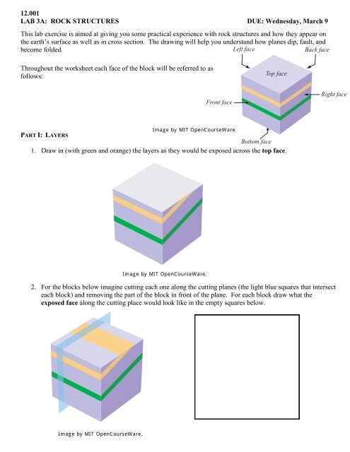
12.001<br />
LAB 3A: ROCK STRUCTURES DUE: Wednesday, March 9<br />
This lab exercise is aimed at giving you some practical experience with rock structures and how they appear on<br />
the earth’s surface as well as in cross section. The drawing will help you understand how planes dip, fault, and<br />
become folded.<br />
Left face<br />
Back face<br />
Throughout the worksheet each face of the block will be referred <strong>to</strong> as<br />
follows:<br />
Top face<br />
Front face<br />
Right face<br />
Image by <strong>MIT</strong> <strong>OpenCourseWare</strong>.<br />
PART I: LAYERS<br />
Bot<strong>to</strong>m face<br />
1. Draw in (with green and orange) the layers as they would be exposed across the <strong>to</strong>p face.<br />
Image by <strong>MIT</strong> <strong>OpenCourseWare</strong>.<br />
2. For the blocks below imagine cutting each one along the cutting planes (the light blue squares that intersect<br />
each block) and removing the part of the block in front of the plane. For each block draw what the<br />
exposed face along the cutting place would look like in the empty squares below.<br />
Image by <strong>MIT</strong> <strong>OpenCourseWare</strong>.
3. Imagine cutting each block along the cutting planes and removing the part of the block in front of the<br />
plane. Draw on the blank blocks below the three exposed faces of both blocks after the cutting plane<br />
has removed the front portion.<br />
Images by <strong>MIT</strong> <strong>OpenCourseWare</strong>.<br />
2
4. These planar layers are at an oblique angle – they are not parallel <strong>to</strong> any face. Using the front and right<br />
sides as a guide, draw on image below how the layers would cross the <strong>to</strong>p face.<br />
Images by <strong>MIT</strong> <strong>OpenCourseWare</strong>.<br />
5. Imagine cutting each block along the gray cutting planes and removing the part of the block in front of<br />
the plane. For both blocks, sketch the exposed front face along the cutting plan after it is cut.<br />
Images by <strong>MIT</strong> <strong>OpenCourseWare</strong>.<br />
3
6. One of the four images below shows a straight-on view of the block from the right after it was cut and<br />
the right portion of the block removed. Circle which of the four choices shows the correct view of the<br />
exposed right face.<br />
Images by <strong>MIT</strong> <strong>OpenCourseWare</strong>.<br />
4
PART II: FOLDS<br />
1. For each syncline below, draw what the exposed face along the cutting plane would look like in the<br />
empty squares.<br />
Images by <strong>MIT</strong> <strong>OpenCourseWare</strong>.<br />
5
2. For both anticlines below, draw what the face exposed along the cutting plane would look like in the<br />
squares provided.<br />
Images by <strong>MIT</strong> <strong>OpenCourseWare</strong>.<br />
3. For the plunging syncline below, sketch the right face of the block.<br />
Image by <strong>MIT</strong> <strong>OpenCourseWare</strong>.<br />
6
4. For each plunging syncline below, draw what the exposed face along the cutting plane would look like in<br />
the squares provided.<br />
Images by <strong>MIT</strong> <strong>OpenCourseWare</strong>.<br />
7
5. Below, the same small block is shown with four different cutting planes. Circle the small image that,<br />
when cut and the front-most portion removed, would result in the image you see above the small squares.<br />
Hint: Pay attention <strong>to</strong> the orientation of the cutting plane and where it intersects each folded layer.<br />
Images by <strong>MIT</strong> <strong>OpenCourseWare</strong>.<br />
8
Answer the following questions:<br />
1. If you were looking at one fold in isolation on the land surface, how would you tell whether it is a<br />
syncline or an anticline?<br />
2. What is the relationship between the plunge of the folds and the dips of the beds located along the axes<br />
of the folds?<br />
3. How would you tell, qualitatively, the dip of the axial plane of a given fold from the dips of the layers<br />
on the two limbs of the fold?<br />
PART III: FAULTS<br />
1. The back half of the block has been faulted <strong>to</strong> the left or right and then eroded <strong>to</strong> form a cube again. In<br />
which direction did the back block shift? (Circle one) What type of fault is represented?<br />
LEFT<br />
RIGHT<br />
Fault type:<br />
Image by <strong>MIT</strong> <strong>OpenCourseWare</strong>.<br />
9
2. In which direction (up or down) has the fault shifted the back block in the image below? (Circle one)<br />
UP<br />
DOWN<br />
Image by <strong>MIT</strong> <strong>OpenCourseWare</strong>.<br />
3. Below, vertical layers have been faulted. The back block has been faulted in one direction only. Which<br />
direction (up, down, left, right) was it? (Circle one) What type of fault is this?<br />
UP<br />
DOWN<br />
LEFT<br />
RIGHT<br />
Fault type:<br />
Image by <strong>MIT</strong> <strong>OpenCourseWare</strong>.<br />
4. With arrows, indicate a possible combination of faulting motions for the back block that would result<br />
in the image below<br />
Image by <strong>MIT</strong> <strong>OpenCourseWare</strong>.<br />
10
5. The block below contains a synclinal fold that has been faulted. In which one direction was the back<br />
block faulted? (Circle one)<br />
UP<br />
DOWN<br />
LEFT<br />
RIGHT<br />
6. If the fault below is an oblique-slip fault, in which directions did the back block get displaced before it<br />
was eroded? (Circle one)<br />
UP and RIGHT<br />
UP and LEFT<br />
DOWN and RIGHT<br />
DOWN and LEFT<br />
Images by <strong>MIT</strong> <strong>OpenCourseWare</strong>.<br />
11
PART 4: RULE OF THE V’S<br />
The purpose of this last part of the lab is <strong>to</strong> get you <strong>to</strong> think about the intersection of geological structures (only<br />
simple planar layers) and <strong>to</strong>pography. When working with geological maps, it is important <strong>to</strong> be able <strong>to</strong> tell<br />
something qualitatively about the dip of a planar feature or a planar layer from how it interacts with irregular<br />
<strong>to</strong>pography.<br />
You’ll find a series of movies that will allow you <strong>to</strong> manipulate the dip of a plane through<br />
<strong>to</strong>pography in three dimensions. On the blank <strong>to</strong>pographic maps below draw the trace of the intersection<br />
between the planar layer (at the dip specified under the map) and <strong>to</strong>pography.<br />
VALLEYS: see movie for “Simple Valley”<br />
Dip: 90° (vertical)<br />
Dip: 0° (horizontal)<br />
12
Dip: Dipping <strong>to</strong> the north<br />
Dip: Dipping <strong>to</strong> the south
<strong>MIT</strong> <strong>OpenCourseWare</strong><br />
http://ocw.mit.edu<br />
12.001 <strong>Introduction</strong> <strong>to</strong> <strong>Geology</strong><br />
Spring 2011<br />
For information about citing these materials or our Terms of Use, visit: http://ocw.mit.edu/terms.