ÇUKUROVA UNIVERSITY INSTITUTE OF NATURAL AND APPLIED ...
ÇUKUROVA UNIVERSITY INSTITUTE OF NATURAL AND APPLIED ... ÇUKUROVA UNIVERSITY INSTITUTE OF NATURAL AND APPLIED ...
4. MODELING OF PROPOSED DVR Mustafa İNCİ 4.3.2. Voltage Injection Strategy Voltage sag and swell problems have several characteristic properties which must be compensate. Sag/swell magnitude and phase jump problem are the most important problems in sensitive loads. Therefore, the voltage injection strategies must be applied depend upon these major issues. The standard solution for compensating voltage sags is to reestablish the exact voltage before the sag. Therefore, the amplitude and the phase of the voltage before the sag have to be exactly restored. The resulting vector is shown in Figure 4.16.(Meyer et al., 2008) Figure 4.16 Phasor diagram of Pre-Sag Compensation methods In PSC method, determining pre-sag angle (θ presag ) is determined by using a phase freezer unit. In literature, conventional phase freezer unit is created by measuring the supply voltage (V s ) and freezing the phase angle of the supply voltage when sag occurs. The phase angle of the supply voltage is used as the reference phase angle of the load voltage (V l ) during sag operation as seen in Figure 4.17 (Delfino et al.,2005; Nielsen et al.,2004; Vilatgamuwa et al.,2002; Ajaei et al.,2011; Köroğlu,2012). 71
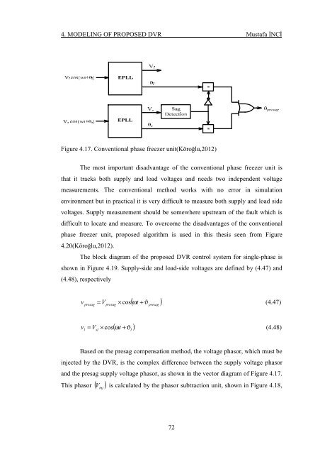
4. MODELING OF PROPOSED DVR Mustafa İNCİ Figure 4.17. Conventional phase freezer unit(Köroğlu,2012) The most important disadvantage of the conventional phase freezer unit is that it tracks both supply and load voltages and needs two independent voltage measurements. The conventional method works with no error in simulation environment but in practical it is very difficult to measure both supply and load side voltages. Supply measurement should be somewhere upstream of the fault which is difficult to locate and measure. To overcome the disadvantages of the conventional phase freezer unit, proposed algorithm is used in this thesis seen from Figure 4.20(Köroğlu,2012). The block diagram of the proposed DVR control system for single-phase is shown in Figure 4.19. Supply-side and load-side voltages are defined by (4.47) and (4.48), respectively v presag presag ( ω t + ϑ ) = V × cos (4.47) presag v l sl ( ω t + ϑ ) = V × cos (4.48) l Based on the presag compensation method, the voltage phasor, which must be injected by the DVR, is the complex difference between the supply voltage phasor and the presag supply voltage phasor, as shown in the vector diagram of Figure 4.17. This phasor ( V inj ) is calculated by the phasor subtraction unit, shown in Figure 4.18, 72
- Page 42 and 43: 3. FUNDAMENTALS OF DVR Mustafa İNC
- Page 44 and 45: 3. FUNDAMENTALS OF DVR Mustafa İNC
- Page 46: 3. FUNDAMENTALS OF DVR Mustafa İNC
- Page 49 and 50: 3. FUNDAMENTALS OF DVR Mustafa İNC
- Page 51 and 52: 3. FUNDAMENTALS OF DVR Mustafa İNC
- Page 53 and 54: 3. FUNDAMENTALS OF DVR Mustafa İNC
- Page 55 and 56: 3. FUNDAMENTALS OF DVR Mustafa İNC
- Page 58: 3. FUNDAMENTALS OF DVR Mustafa İNC
- Page 61 and 62: 3. FUNDAMENTALS OF DVR Mustafa İNC
- Page 63: 3. FUNDAMENTALS OF DVR Mustafa İNC
- Page 66 and 67: 4. MODELING OF PROPOSED DVR Mustafa
- Page 68 and 69: 4. MODELING OF PROPOSED DVR Mustafa
- Page 70 and 71: 4. MODELING OF PROPOSED DVR Mustafa
- Page 72 and 73: 4. MODELING OF PROPOSED DVR Mustafa
- Page 74 and 75: 4. MODELING OF PROPOSED DVR Mustafa
- Page 76 and 77: 4. MODELING OF PROPOSED DVR Mustafa
- Page 78 and 79: 4. MODELING OF PROPOSED DVR Mustafa
- Page 81 and 82: 4. MODELING OF PROPOSED DVR Mustafa
- Page 83 and 84: 4. MODELING OF PROPOSED DVR Mustafa
- Page 85 and 86: 4. MODELING OF PROPOSED DVR Mustafa
- Page 88 and 89: 4. MODELING OF PROPOSED DVR Mustafa
- Page 92: 4. MODELING OF PROPOSED DVR Mustafa
- Page 95 and 96: 4. MODELING OF PROPOSED DVR Mustafa
- Page 97 and 98: 4. MODELING OF PROPOSED DVR Mustafa
- Page 100 and 101: 4. MODELING OF PROPOSED DVR Mustafa
- Page 102 and 103: 5. SIMULATION RESULTS AND CASE STUD
- Page 104 and 105: 5. SIMULATION RESULTS AND CASE STUD
- Page 106 and 107: 5. SIMULATION RESULTS AND CASE STUD
- Page 108 and 109: 5. SIMULATION RESULTS AND CASE STUD
- Page 110 and 111: 5. SIMULATION RESULTS AND CASE STUD
- Page 112 and 113: 5. SIMULATION RESULTS AND CASE STUD
- Page 114 and 115: 5. SIMULATION RESULTS AND CASE STUD
- Page 116 and 117: 5. SIMULATION RESULTS AND CASE STUD
- Page 118 and 119: 5. SIMULATION RESULTS AND CASE STUD
- Page 120 and 121: 5. SIMULATION RESULTS AND CASE STUD
- Page 122 and 123: 5. SIMULATION RESULTS AND CASE STUD
- Page 124 and 125: 5. SIMULATION RESULTS AND CASE STUD
- Page 126 and 127: 5. SIMULATION RESULTS AND CASE STUD
- Page 128 and 129: 6. CONCLUSION Mustafa İNCİ 6. CON
- Page 130 and 131: 6. CONCLUSION Mustafa İNCİ • En
- Page 132 and 133: DELFINO, B., FORNARI, F., PROCOPIO,
- Page 134 and 135: KARIMI-GHARTEMANI M., IRAVANI M.R.
- Page 136 and 137: OĞUZ, G., 2004. Performance Of A D
- Page 138 and 139: TESTA A., AKRAM M.F., BURCH R., CAR
4. MODELING <strong>OF</strong> PROPOSED DVR Mustafa İNCİ<br />
Figure 4.17. Conventional phase freezer unit(Köroğlu,2012)<br />
The most important disadvantage of the conventional phase freezer unit is<br />
that it tracks both supply and load voltages and needs two independent voltage<br />
measurements. The conventional method works with no error in simulation<br />
environment but in practical it is very difficult to measure both supply and load side<br />
voltages. Supply measurement should be somewhere upstream of the fault which is<br />
difficult to locate and measure. To overcome the disadvantages of the conventional<br />
phase freezer unit, proposed algorithm is used in this thesis seen from Figure<br />
4.20(Köroğlu,2012).<br />
The block diagram of the proposed DVR control system for single-phase is<br />
shown in Figure 4.19. Supply-side and load-side voltages are defined by (4.47) and<br />
(4.48), respectively<br />
v<br />
presag<br />
presag<br />
( ω t + ϑ )<br />
= V × cos (4.47)<br />
presag<br />
v<br />
l<br />
sl<br />
( ω t + ϑ )<br />
= V × cos (4.48)<br />
l<br />
Based on the presag compensation method, the voltage phasor, which must be<br />
injected by the DVR, is the complex difference between the supply voltage phasor<br />
and the presag supply voltage phasor, as shown in the vector diagram of Figure 4.17.<br />
This phasor ( V<br />
inj<br />
) is calculated by the phasor subtraction unit, shown in Figure 4.18,<br />
72


