ÇUKUROVA UNIVERSITY INSTITUTE OF NATURAL AND APPLIED ...
ÇUKUROVA UNIVERSITY INSTITUTE OF NATURAL AND APPLIED ...
ÇUKUROVA UNIVERSITY INSTITUTE OF NATURAL AND APPLIED ...

You also want an ePaper? Increase the reach of your titles
YUMPU automatically turns print PDFs into web optimized ePapers that Google loves.
3. FUNDAMENTALS <strong>OF</strong> DVR Mustafa İNCİ<br />
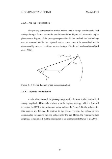
3.3.3.1. Pre-sag compensation<br />
The pre-sag compensation method tracks supply voltage continuously load<br />
voltage during a fault to restore the pre-fault condition. Figure 3.13 shows the singlephase<br />
vector diagram of the pre-sag compensation. In this method, the load voltage<br />
can be restored ideally, but injected active power cannot be controlled and is<br />
determined by external conditions such as the type of faults and load condition (Quirl<br />
et al., 2006).<br />
Figure 3.13. Vector diagram of pre-sag compensation<br />
3.3.3.2. In-phase compensation<br />
As already mentioned, the pre-sag compensation does not lead to a minimized<br />
voltage amplitude. This can be realized with the in-phase strategy, which is designed<br />
to control the DVR with a minimum output voltage. In Figure 3.14, the voltages for<br />
this strategy are depicted. In contrast to the pre-sag version, the voltage is now<br />
compensated in phase to the grid voltage after the sag. Hence, the required voltage<br />
amplitude is minimized, but the phase jump is not compensated (Meyer et al., 2008).<br />
34