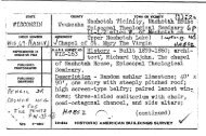
Dorrance Colliery Fan Complex: 1884, 1908, Ca. 1930 HAER No ...
Dorrance Colliery Fan Complex: 1884, 1908, Ca. 1930 HAER No ...
Dorrance Colliery Fan Complex: 1884, 1908, Ca. 1930 HAER No ...

Create successful ePaper yourself
Turn your PDF publications into a flip-book with our unique Google optimized e-Paper software.
Ho -v^vi^b<br />
HIST0R1C AMERICAN ENGINEERING RECORD<br />
Index to Photographs<br />
<strong>HAER</strong> <strong>No</strong>. PA-61<br />
<strong>Dorrance</strong> <strong>Colliery</strong> <strong>Fan</strong> <strong>Complex</strong>: <strong>1884</strong>, <strong>1908</strong>, <strong>Ca</strong>. <strong>1930</strong> <strong>HAER</strong> <strong>No</strong>, PA-61<br />
Lehigh Valley Coal Company<br />
South Side of Susquehanna River at<br />
Route 115 and Riechard Street<br />
Wilkes-Barre<br />
Luzerne County<br />
Pennsylvania<br />
NOTE: These photographs are government materials and not subject<br />
to copyright. However, the courtesy of a credit line<br />
identifying the Historic American Engineering Record and the<br />
photographs would be appreciated. All photographs were taken<br />
by Pierce Bounds in June 1983.<br />
PA 61-1<br />
EXTERIOR VIEW OF NEW FAN HOUSE AND HILLMAN FAN HOUSE LOOKING NORTHWEST<br />
The building on the left, the New <strong>Fan</strong> House, houses a Corliss steam<br />
engine which powered a Buffalo Forge Company single inlet Duplex<br />
Conoidal centrifugal exhausted fan through a metal updraft chimney.<br />
Part of the brick airway leading to the Baltimore shaft is visible<br />
to its right rear. The Hillman <strong>Fan</strong> House, on the right, houses the<br />
1883 double inlet Guibal fan. The south entry, the curve of the fan<br />
housing, and brick updraft chimney are visible in this view.<br />
PA 61-2<br />
EXTERIOR VIEW OF NEW FAN HOUSE AND HILLMAN FAN HOUSE LOOKING NORTHEAST<br />
The New <strong>Fan</strong> House is in the foreground; the metal fan housing and<br />
updraft chimney are attached to the north side. The Hillman <strong>Fan</strong><br />
House is in the background; the brick airway, fan housing, and<br />
updraft chimney are visible.<br />
PA 61-3<br />
EXTERIOR VIEW OF HILLMAN FAN HOUSE LOOKING NORTH<br />
The airway, with sloping concrete roof, is in the foreground. Two<br />
periods of construction are evident. In the center of the wall, to
-2-<br />
DORRANCE COLLIERY FAN COMPLEX<br />
Index to Photographs<br />
<strong>HAER</strong> <strong>No</strong>. PA-61<br />
the left of the window, is a cover over the air velocity indicator.<br />
The building houses a 35 foot diameter cast iron and wood Guibal<br />
centrifugal fan. The curve of the fan housing with its iron roof<br />
are in the middle ground, and the rectangular upshaft chimney is in<br />
the background. The brick, metal, and concrete building was<br />
designed to be fireproof. The metal upshaft chimney of the New <strong>Fan</strong><br />
House is to the left.<br />
PA 61-4<br />
EXTERIOR VIEW OF HILLMAN FAN HOUSE LOOKING NORTHEAST<br />
This view shows the concrete roof covering the airways and the<br />
engine room. The reinforced concrete roof is supported by metal<br />
beams. <strong>No</strong>te how the airshaft, in the foreground, widens to create<br />
an airway on either side for the double inlet fan. The brick fan<br />
housing is capped by a curved sheet metal roof whose segments are<br />
bolted together. The brick updraft chimney, capped with concrete,<br />
is to the rear (northeast). Also evident on the wall is the cover<br />
over the air velocity indicator. The Hollenback Cemetery, which<br />
adjoins the <strong>Dorrance</strong> <strong>Colliery</strong> property is in the background.<br />
PA 61-5<br />
EXTERIOR VIEW OF HILLMAN FAN HOUSE LOOKING NORTHWEST<br />
The airway, with its airlock entryway is in the foreground. <strong>No</strong>te<br />
the concrete foundation, steps, and sidewalks. The curved fan<br />
housing and edge of the iron roof are incorporated into the upshaft<br />
chimney; the lighter colored brick in the western section indicates<br />
either a modification or expansion of the chimney. The interior<br />
curve of the chimney is evident in the upper section of the right<br />
(east) wall of the chimney.<br />
PA 61-6<br />
EXTERIOR VIEW OF HILLMAN FAN HOUSE LOOKING WEST<br />
The engine house is on the right. The end of the 1883 Pittston<br />
Steam Engine cylinder head and steam chest is visible in the doorway.<br />
Although its stairs are missing, the iron framing of a porch<br />
stands in front of what was a doorway. The entrance door to the<br />
north airlock is visible inside the enlarged window. The end view<br />
of the upshaft chimney shows the brick ribbing for support, the<br />
brick corbelling, and concrete capstones.
-3-<br />
DORRANCE COLLIERY FAN COMPLEX<br />
Index to Photographs<br />
<strong>HAER</strong> <strong>No</strong>. PA-61<br />
PA 61-7<br />
EXTERIOR VIEW OF BALTIMORE FAN HOUSE, AIRWAY, AND HILLMAN FAN HOUSE<br />
LOOKING SOUTHEAST<br />
The roof of the <strong>1908</strong> Baltimore <strong>Fan</strong> House is to the left; the doorway<br />
opens onto the rear of the metal fan housing. In the immediate foreground<br />
is a section of the blast doors installed in the airway directly<br />
over the shaft to protect the fans in case of a mine explosion. The<br />
sloping airway, to the right, connects with the New <strong>Fan</strong> House, whose<br />
metal updraft chimney is evident in the right background. The engine<br />
house of the Hillman <strong>Fan</strong> House is in the left background with the fan<br />
housing and updraft chimney connected. The boiler house stack is in<br />
the background. All of the engines in the fan complex were powered<br />
by the boiler house.<br />
PA 61-8<br />
EXTERIOR VIEW OF BALTIMORE FAN HOUSE LOOKING NORTHEAST<br />
The engine room and south airway are in the foreground. The brick<br />
walls covering the fan housing and brick upshaft chimney are in the<br />
background. The engine room, fan housing, and airways are covered<br />
with reinforced concrete roofing. In the left foreground is an<br />
airlock leading into the airway.<br />
PA 61-9<br />
EXTERIOR VIEW OF BALTIMORE FAN HOUSE LOOKING NORTHEAST<br />
The brick and concrete construction of the engine room, airways, and<br />
chimney are evident. The shaft housing and flywheel of the Allis-<br />
Chalmers Corliss steam engine are visible through the window of the<br />
engine room.<br />
PA 61-10<br />
EXTERIOR VIEW OF STONE RETAINING WALL, AIRWAY, BALTIMORE FAN HOUSE<br />
AND HILLMAN FAN HOUSE LOOKING EAST<br />
The stone retaining wall encloses a pit which may have been the ori<br />
ginal site of the Hillman <strong>Fan</strong> House steam engine. The concrete<br />
foundations in the left foreground are more recent (c. <strong>1930</strong>) additions<br />
which may be supports for a porch or stairway. The sloping<br />
airshaft, in the middle ground, connected the Baltimore shaft to
*-i<br />
-4-<br />
DORRANCE COLLIERY FAN COMPLEX<br />
Index to Photographs<br />
<strong>HAER</strong> <strong>No</strong>. PA-61<br />
the New <strong>Fan</strong> House (not shown) and Hillman <strong>Fan</strong> House in the background.<br />
The Hillman engine house is on the left.<br />
PA 61-11<br />
EXTERIOR VIEW OF NEW FAN HOUSE LOOKING EAST<br />
The airway (on the left) leads from the Baltimore shaft to the New<br />
<strong>Fan</strong> House. The metal housing (center foreground) encases a single<br />
entry Duplex Conoidal fan, made by the Buffalo Forge Company. The<br />
Duplex Conoidal fan had two parts: a disk fan which drew air up the<br />
airway and a centrifugal fan set at a right angle to it which<br />
exhausted the air. The engine house (on the right) contains a<br />
direct connected Corliss engine.<br />
PA 61-12<br />
EXTERIOR VIEW OF NEW FAN HOUSE LOOKING WEST<br />
The engine room with the cylinder head of the Corliss steam visible<br />
through the open door is on the left (south). The metal updraft<br />
chimney is in the center and part of the airway, with a door leading<br />
into an airlock, is on the right.<br />
PA 61-13<br />
INTERIOR VIEW OF HILLMAN FAN HOUSE LOOKING NORTHEAST<br />
This view, taken in the southern airway, shows the circular brickwork<br />
surrounding the air intake, the cast iron shaft support, and<br />
one of the 1883 Guibal fan cast iron spiders. Three cast iron<br />
spiders support the ten feet by eleven feet wooden paddles.<br />
Remnants of the catwalk with its screen grating lead to the inner<br />
door of the airlock. <strong>No</strong>te also the support beams and reinforced<br />
concrete roof. The concrete floor of the airway has deteriorated.<br />
PA 61-14<br />
INTERIOR VIEW OF HILLMAN FAN HOUSE LOOKING SOUTHEAST<br />
This view of the north airway shows the shaft support, bracing, and<br />
shaft coupling of the 1883 Guibal fan. The shaft was direct connected<br />
to the steam engine. Behind the circular brickwork are the
-5-<br />
DORRANCE COLLIERY FAN COMPLEX<br />
Index to Photographs<br />
<strong>HAER</strong> <strong>No</strong>. PA-61<br />
cast iron spiders to which the supports for the wooden paddles are<br />
attached. One of the ten feet by eleven feet paddles is visible<br />
above the shaft in the center of the photo. Remnants of the catwalk,<br />
under the shaft, lead to the inner door of the catwalk. The<br />
catwalk was used by the men who oiled the shaft bearings.<br />
PA 61-15<br />
INTERIOR VIEW OF HILLMAN FAN HOUSE LOOKING WEST<br />
The <strong>No</strong>. 2 (Hillman) shaft is on the other side of the rail barrier.<br />
In the background are the ventilating doors leading to the airway<br />
from the <strong>No</strong>. 4 (Baltimore) shaft. The brick wall on the left is<br />
pointed; it splits the air directing it to both sides of the double<br />
inlet Guibal centrifugal fan. The concrete rail support also is<br />
pointed to reduce air resistance. The rails are recycled light<br />
guage mine railroad tracks. The alterations to the fan house are<br />
evident in the left background, where a sloping joint between the<br />
concrete and brick suggests an earlier roof pitched the other way.<br />
PA 61-16<br />
INTERIOR VIEW OF HILLMAN FAN HOUSE ENGINE ROOM LOOKING EAST<br />
This overview of the 1883 Pittston Engine and Machine Company steam<br />
engine includes the flywheel and pillowblock in the foreground, with<br />
the shaft and cylinder in the background. The engine is a horizontal,<br />
slide valve type of 30 inch bore and 60 inch stroke that turned<br />
the fan at 49 revolutions per minute.<br />
PA 61-17<br />
INTERIOR VIEW OF HILLMAN FAN HOUSE ENGINE ROOM LOOKING EAST<br />
The direct-acting 1883 Pittston Engine and Machine Company steam<br />
engine was made by George A. Parrish and W. B. Culver of West<br />
Pittston, Pennsylvania.<br />
PA 61-18<br />
INTERIOR VIEW OF BALTIMORE FAN HOUSE ENGINE ROOM LOOKING EAST<br />
The flywheel of the <strong>1908</strong> Allis-Chalmers Corliss steam engine and<br />
flywheel are in the foreground. The engine is a horizontal slide
-6-<br />
DORRANCE COLLIERY FAN COMPLEX<br />
Index to Photographs<br />
<strong>HAER</strong> <strong>No</strong>. PA-61<br />
valve type with a 24 inch bore and 48 inch stroke. It was direct<br />
connected to the Dickson Guibal fan which rotated at 69 revolutions<br />
per minute.<br />
PA 61-19<br />
INTERIOR VIEW OF BALTIMORE FAN HOUSE LOOKING NORTHEAST<br />
This view of the south airway shows the circular brick opening<br />
through which air was drawn to the center of the 28 foot diameter<br />
Dickson Guibal double inlet fan. <strong>No</strong>te the solid core of the<br />
Dickson-Guibal centrifugal fan and the bracing for the steel<br />
paddles. The shaft, shaft support and braces, and catwalk are<br />
in the right foreground.<br />
PA 61-20<br />
INTERIOR VIEW OF NO. 4 AIRWAY AND NEW FAN HOUSE LOOKING SOUTH<br />
The <strong>No</strong>. 4 (Baltimore) shaft would be directly behind the viewer.<br />
The ventilating doors leading to the Hillman <strong>Fan</strong> House are to the<br />
left. The floor of the airway, once covered with concrete, has<br />
deteriorated. In the background is the metal disk fan, part of the<br />
Duplex Conoidal <strong>Fan</strong> installed in the New <strong>Fan</strong> House. The ladder provides<br />
access to the shaft bearings.<br />
PA 61-21<br />
INTERIOR VIEW OF NEW FAN HOUSE LOOKING SOUTH<br />
The single entry Duplex Conoidal fan had a disk fan, pictured here,<br />
which drew air from the <strong>No</strong>. 4 (Baltimore) shaft up the airway into a<br />
centrifugal fan (see PA 61-22) and out the upshaft chimney. The<br />
ladder provided access to the shaft bearings; the mesh screen was a<br />
safety feature. The door to the left leads into an airlock.<br />
PA 61-22<br />
INTERIOR VIEW OF NEW FAN HOUSE UPSHAFT CHIMNEY LOOKING WEST<br />
The Duplex Conoidal <strong>Fan</strong> is a single entry disk fan (see PA 61-21 and<br />
PA 61-22) which drew air from the <strong>No</strong>. 4 (Baltimore) shaft up the airway<br />
through the cone, seen on the right, into the centrifugal fan,<br />
pictured here. The curved metal blades forced the air from the
-7-<br />
DORRANCE COLLIERY FAN COMPLEX<br />
Index to Photographs<br />
<strong>HAER</strong> <strong>No</strong>. PA-61<br />
center of the fan to the tips of the blades and out the sheet metal<br />
exhaust chimney.<br />
PA 61-23<br />
INTERIOR VIEW OF NEW FAN HOUSE ENGINE ROOM LOOKING EAST<br />
The flywheel, shaft, and coupling of the c. <strong>1930</strong> Buffalo Forge<br />
Corliss engine are shown.<br />
PA 61-24<br />
INTERIOR VIEW OF NEW FAN HOUSE LOOKING SOUTHWEST<br />
A section of the cylinder, parts of the Corliss linkages, and the<br />
shaft are shown.