Coherent Backscattering from Multiple Scattering Systems - KOPS ...
Coherent Backscattering from Multiple Scattering Systems - KOPS ...
Coherent Backscattering from Multiple Scattering Systems - KOPS ...

You also want an ePaper? Increase the reach of your titles
YUMPU automatically turns print PDFs into web optimized ePapers that Google loves.
5.2 The coherent backscattering cone in high resolution<br />
2048<br />
3.7<br />
2048<br />
x 10 4<br />
4.4<br />
3.6<br />
4.2<br />
1024<br />
3.5<br />
3.4<br />
3.3<br />
3.2<br />
x 10 4 1 1024 2048<br />
1024<br />
4<br />
3.8<br />
3.6<br />
3.1<br />
3.4<br />
1<br />
1 1024 2048<br />
3<br />
1<br />
3.2<br />
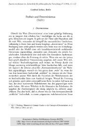
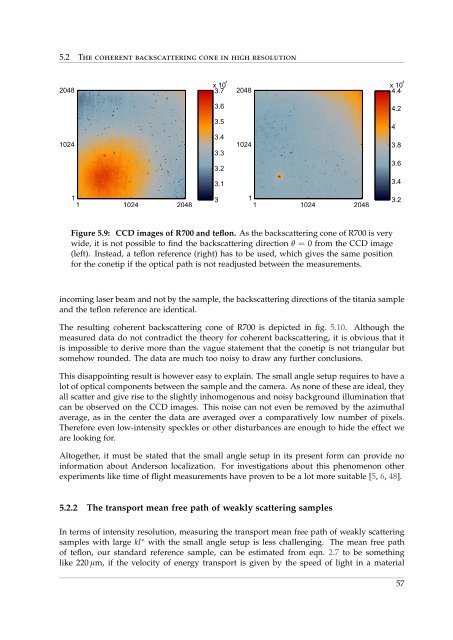
Figure 5.9: CCD images of R700 and teflon. As the backscattering cone of R700 is very<br />
wide, it is not possible to find the backscattering direction θ = 0 <strong>from</strong> the CCD image<br />
(left). Instead, a teflon reference (right) has to be used, which gives the same position<br />
for the conetip if the optical path is not readjusted between the measurements.<br />
incoming laser beam and not by the sample, the backscattering directions of the titania sample<br />
and the teflon reference are identical.<br />
The resulting coherent backscattering cone of R700 is depicted in fig. 5.10. Although the<br />
measured data do not contradict the theory for coherent backscattering, it is obvious that it<br />
is impossible to derive more than the vague statement that the conetip is not triangular but<br />
somehow rounded. The data are much too noisy to draw any further conclusions.<br />
This disappointing result is however easy to explain. The small angle setup requires to have a<br />
lot of optical components between the sample and the camera. As none of these are ideal, they<br />
all scatter and give rise to the slightly inhomogenous and noisy background illumination that<br />
can be observed on the CCD images. This noise can not even be removed by the azimuthal<br />
average, as in the center the data are averaged over a comparatively low number of pixels.<br />
Therefore even low-intensity speckles or other disturbances are enough to hide the effect we<br />
are looking for.<br />
Altogether, it must be stated that the small angle setup in its present form can provide no<br />
information about Anderson localization. For investigations about this phenomenon other<br />
experiments like time of flight measurements have proven to be a lot more suitable [5, 6, 48].<br />
5.2.2 The transport mean free path of weakly scattering samples<br />
In terms of intensity resolution, measuring the transport mean free path of weakly scattering<br />
samples with large kl ∗ with the small angle setup is less challenging. The mean free path<br />
of teflon, our standard reference sample, can be estimated <strong>from</strong> eqn. 2.7 to be something<br />
like 220 µm, if the velocity of energy transport is given by the speed of light in a material<br />
57