Coherent Backscattering from Multiple Scattering Systems - KOPS ...
Coherent Backscattering from Multiple Scattering Systems - KOPS ...
Coherent Backscattering from Multiple Scattering Systems - KOPS ...

You also want an ePaper? Increase the reach of your titles
YUMPU automatically turns print PDFs into web optimized ePapers that Google loves.
3.4 Time Of Flight Setup<br />
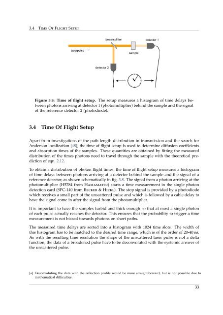
Figure 3.8: Time of flight setup. The setup measures a histogram of time delays between<br />
photons arriving at detector 1 (photomultiplier) behind the sample and the signal<br />
of the reference detector 2 (photodiode).<br />
3.4 Time Of Flight Setup<br />
Apart <strong>from</strong> investigations of the path length distribution in transmission and the search for<br />
Anderson localization [48], the time of flight setup is used to determine diffusion coefficients<br />
and absorption times of the samples. These quantities are obtained by fitting the measured<br />
distribution of the times photons need to travel through the sample with the theoretical prediction<br />
of eqn. 2.12.<br />
To obtain a distribution of photon flight times, the time of flight setup measures a histogram<br />
of time delays between photons arriving at a detector behind the sample and the signal of a<br />
reference detector, as shown schematically in fig. 3.8. The signal <strong>from</strong> a photon arriving at the<br />
photomultiplier (H5784 <strong>from</strong> Hamamatsu) starts a time measurement in the single photon<br />
detection card (SPC-140 <strong>from</strong> Becker & Hickl). The stop signal is provided by a photodiode<br />
which receives a small part of the unscattered pulse and which is followed by a cable delay to<br />
have the signal come in after the signal <strong>from</strong> the photomultiplier.<br />
It is important to have the samples turbid and thick enough so that at most a single photon<br />
of each pulse actually reaches the detector. This ensures that the probability to trigger a time<br />
measurement is not biased towards photons on short paths.<br />
The measured time delays are sorted into a histogram with 1024 time slots. The width of<br />
this histogram has to be matched to the desired time range, which is of the order of 20-40 ns.<br />
As with the resulting time resolution the shape of the unscattered laser pulse is not a delta<br />
function, the data of a broadened pulse have to be deconvoluted with the systemic answer of<br />
the unscattered pulse.<br />
[a] Deconvoluting the data with the reflection profile would be more straightforward, but is not possible due to<br />
mathematical difficulties.<br />
33