Coherent Backscattering from Multiple Scattering Systems - KOPS ...
Coherent Backscattering from Multiple Scattering Systems - KOPS ...
Coherent Backscattering from Multiple Scattering Systems - KOPS ...

Create successful ePaper yourself
Turn your PDF publications into a flip-book with our unique Google optimized e-Paper software.
3.3 Small Angle Setup<br />
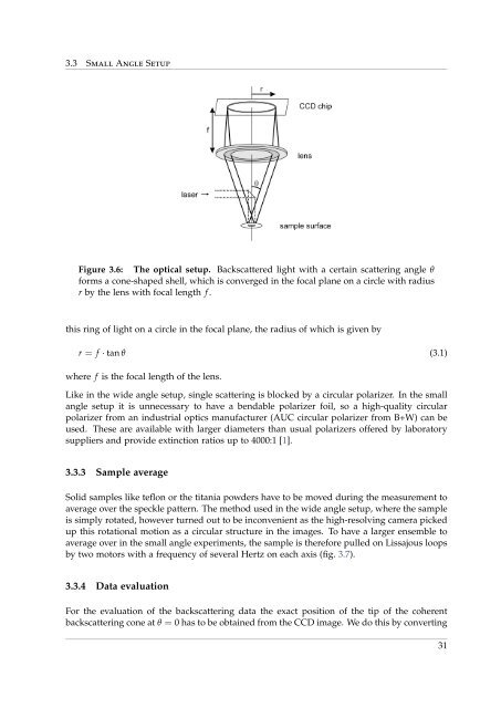
Figure 3.6: The optical setup. Backscattered light with a certain scattering angle θ<br />
forms a cone-shaped shell, which is converged in the focal plane on a circle with radius<br />
r by the lens with focal length f .<br />
this ring of light on a circle in the focal plane, the radius of which is given by<br />
r = f · tan θ (3.1)<br />
where f is the focal length of the lens.<br />
Like in the wide angle setup, single scattering is blocked by a circular polarizer. In the small<br />
angle setup it is unnecessary to have a bendable polarizer foil, so a high-quality circular<br />
polarizer <strong>from</strong> an industrial optics manufacturer (AUC circular polarizer <strong>from</strong> B+W) can be<br />
used. These are available with larger diameters than usual polarizers offered by laboratory<br />
suppliers and provide extinction ratios up to 4000:1 [1].<br />
3.3.3 Sample average<br />
Solid samples like teflon or the titania powders have to be moved during the measurement to<br />
average over the speckle pattern. The method used in the wide angle setup, where the sample<br />
is simply rotated, however turned out to be inconvenient as the high-resolving camera picked<br />
up this rotational motion as a circular structure in the images. To have a larger ensemble to<br />
average over in the small angle experiments, the sample is therefore pulled on Lissajous loops<br />
by two motors with a frequency of several Hertz on each axis (fig. 3.7).<br />
3.3.4 Data evaluation<br />
For the evaluation of the backscattering data the exact position of the tip of the coherent<br />
backscattering cone at θ = 0 has to be obtained <strong>from</strong> the CCD image. We do this by converting<br />
31