Coherent Backscattering from Multiple Scattering Systems - KOPS ...
Coherent Backscattering from Multiple Scattering Systems - KOPS ...
Coherent Backscattering from Multiple Scattering Systems - KOPS ...

You also want an ePaper? Increase the reach of your titles
YUMPU automatically turns print PDFs into web optimized ePapers that Google loves.
2.4 The influence of boundaries<br />
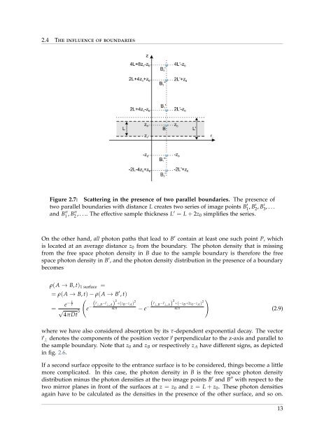
Figure 2.7: <strong>Scattering</strong> in the presence of two parallel boundaries. The presence of<br />
two parallel boundaries with distance L creates two series of image points B<br />
1 ′ , B′ 2 , B′ 3 , . . .<br />
and B<br />
1 ′′,<br />
B′′ 2 , . . .. The effective sample thickness L′ = L + 2z 0 simplifies the series.<br />
On the other hand, all photon paths that lead to B ′ contain at least one such point P, which<br />
is located at an average distance z 0 <strong>from</strong> the boundary. The photon density that is missing<br />
<strong>from</strong> the free space photon density in B due to the sample boundary is therefore the free<br />
space photon density in B ′ , and the photon density distribution in the presence of a boundary<br />
becomes<br />
ρ(A → B, t) 1 surface =<br />
= ρ(A → B, t) − ρ(A → B ′ , t)<br />
= e− τ<br />
t<br />
√<br />
(e ( − ⃗r ⊥,B −⃗r ⊥,A) 2 +(z B −z A ) 2<br />
4Dt − e ( − ⃗r ⊥,B −⃗r ⊥,A) 2 +(−z B +2z 0 −z A ) 2<br />
4Dt<br />
3<br />
4πDt<br />
)<br />
(2.9)<br />
where we have also considered absorption by its τ-dependent exponential decay. The vector<br />
⃗r ⊥ denotes the components of the position vector⃗r perpendicular to the z-axis and parallel to<br />
the sample boundary. Note that z 0 and z B or respectively z A have different signs, as depicted<br />
in fig. 2.6.<br />
If a second surface opposite to the entrance surface is to be considered, things become a little<br />
more complicated. In this case, the photon density in B is the free space photon density<br />
distribution minus the photon densities at the two image points B ′ and B ′′ with respect to the<br />
two mirror planes in front of the surfaces at z = z 0 and z = L + z 0 . These photon densities<br />
again have to be calculated as the densities in the presence of the other surface, and so on.<br />
13