Etching methodologies in -oriented silicon wafers ...
Etching methodologies in -oriented silicon wafers ...
Etching methodologies in -oriented silicon wafers ...

You also want an ePaper? Increase the reach of your titles
YUMPU automatically turns print PDFs into web optimized ePapers that Google loves.
390 JOURNAL OF MICROELECTROMECHANICAL SYSTEMS, VOL. 9, NO. 3, SEPTEMBER 2000<br />
<strong>Etch<strong>in</strong>g</strong> Methodologies <strong>in</strong> 111 -Oriented<br />
Silicon Wafers<br />
R. Edw<strong>in</strong> Oosterbroek, J. W. (Erw<strong>in</strong>) Berenschot, Henri V. Jansen, A. Jasper Nijdam, Grégory Pandraud,<br />
Albert van den Berg, and Miko C. Elwenspoek, Member, IEEE<br />
Abstract—New <strong>methodologies</strong> <strong>in</strong> anisotropic wet-chemical<br />
etch<strong>in</strong>g of 111 -<strong>oriented</strong> <strong>silicon</strong>, allow<strong>in</strong>g useful process designs<br />
comb<strong>in</strong>ed with smart mask-to-crystal-orientation-alignment are<br />
presented <strong>in</strong> this paper. The described methods yield smooth surfaces<br />
as well as high-quality plan-parallel beams and membranes.<br />
With a comb<strong>in</strong>ation of pre-etch<strong>in</strong>g and wall passivation, structures<br />
can be etched at different depths <strong>in</strong> a wafer. Designs, us<strong>in</strong>g the<br />
111 -crystal orientation, supplemented with pictures of fabricated<br />
devices, demonstrate the potential of us<strong>in</strong>g 111 -<strong>oriented</strong><br />
<strong>wafers</strong> <strong>in</strong> microsystem design. [523]<br />
Index Terms—Bulk micromach<strong>in</strong><strong>in</strong>g, etch technology, 111<br />
<strong>wafers</strong>, reactive ion etch<strong>in</strong>g, wet chemical etch<strong>in</strong>g.<br />
I. INTRODUCTION<br />
IN MICROSYSTEM technology, bulk etch<strong>in</strong>g techniques<br />
have found a strong position next to surface micromach<strong>in</strong><strong>in</strong>g<br />
techniques [1]. With bulk etch<strong>in</strong>g, rigid high qualitative<br />
monocrystall<strong>in</strong>e structures can be etched. In contrast to surface<br />
micromach<strong>in</strong><strong>in</strong>g, pre-stress, creep, and stress relaxation are<br />
less pronounced and better fatigue resistance is obta<strong>in</strong>ed [2].<br />
Therefore, bulk etch<strong>in</strong>g techniques are very well suited for application<br />
areas where high demands are put on the mechanical<br />
and time-dependent material properties. Another advantage is<br />
the possibility to fabricate microstructures, built from rather<br />
thick material layers, cavities, and trenches well over a few<br />
micrometers <strong>in</strong> depth. Besides, the bulk processed <strong>silicon</strong><br />
structures can be used as a mould to grow other construction<br />
materials <strong>in</strong>. Examples are channels for micro total analysis<br />
applications [3], [4].<br />
For these applications, mostly - and -<strong>oriented</strong> <strong>silicon</strong><br />
are used for their fast etch rates <strong>in</strong> the out-of-plane directions<br />
<strong>in</strong> anisotropic wet chemical etchants like potassium hydroxide<br />
(KOH). Also, -<strong>oriented</strong> <strong>silicon</strong> is used s<strong>in</strong>ce nice<br />
deep trenches with straight walls with respect to the wafer sur-<br />
Manuscript received January 6, 2000; revised June 13, 2000. This work was<br />
supported by the Onderwijs Stimuler<strong>in</strong>gsfonds of the University of Twente, Enschede,<br />
The Netherlands, and by the Dutch Technology Foundation. Subject<br />
Editor, E. Obermeier.<br />
R. E. Oosterbroek, J. W. Berenschot, A. J. Nijdam, M. C. Elwenspoek are<br />
with the Transducers Technology Laboratory, Electrical Eng<strong>in</strong>eer<strong>in</strong>g Department,<br />
MESA+ Research Institute, Univerity of Twente, 7500 AE Enschede,<br />
The Netherlands.<br />
H. V. Jansen is with the Inter-University Microelectronics Center, Leuven<br />
B-3001, Belgium.<br />
G. Pandraud is with Bookham Technology Ltd., OX14 4RY Ab<strong>in</strong>gdon, U.K.<br />
A. van den Berg is with the M<strong>in</strong>iaturized (Bio)Chemical Analysis Systems<br />
Group, Electrical Eng<strong>in</strong>eer<strong>in</strong>g Department, MESA+ Research Institute, University<br />
of Twente, 7500 AE Enschede, The Netherlands.<br />
Publisher Item Identifier S 1057-7157(00)08027-6.<br />
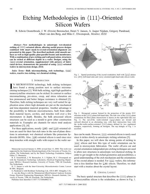
Fig. 1. Spatial position<strong>in</strong>g of the crystal octahedron, built with f111g-planes<br />
<strong>in</strong> a h100i (left-hand side) and h111i-<strong>oriented</strong> (right-hand side) <strong>silicon</strong> wafer.<br />
Fig. 2. Hexagonal contour formed by the projection of the atomic FCC<br />
structure on the f111g-plane (left-hand side). The side view of the f111g-plane<br />
orientations for three plane <strong>in</strong>tersections is shown on the right-hand side (see<br />
Fig. 1). The out-of-the wafer-<strong>oriented</strong> f111g-planes are <strong>in</strong>ward and<br />
outward directed <strong>in</strong> an alternat<strong>in</strong>g way, with their <strong>in</strong>tersection l<strong>in</strong>es with<br />
the <strong>in</strong>-the-wafer-surface-<strong>oriented</strong> f111g-planes def<strong>in</strong>ed by two equilateral<br />
triangles, respectively, form<strong>in</strong>g an hexagon. The top triangle of Fig. 1 is<br />
accented.<br />
face can be made. However, -<strong>oriented</strong> <strong>silicon</strong> is rarely used<br />
s<strong>in</strong>ce it etches slowly <strong>in</strong> anisotropic etch<strong>in</strong>g solutions [5].<br />
In this paper, we will show the strong po<strong>in</strong>ts of etch<strong>in</strong>g <strong>in</strong><br />
<strong>silicon</strong> and how this type of wafer orientation can be<br />
used <strong>in</strong> microsystem fabrication. The wafer off-axis cut and<br />
crystal-orientation-<strong>in</strong>dependent pre-etch<strong>in</strong>g techniques are used<br />
to allow new structures <strong>in</strong> anisotropic wet-chemical etch<strong>in</strong>g. In<br />
order to get <strong>in</strong>sight <strong>in</strong> the etched geometries and possibilities, a<br />
good understand<strong>in</strong>g of the etch mechanism and the orientations<br />
of the crystal planes is needed. For <strong>wafers</strong>, this <strong>in</strong>formation<br />
is less familiar than for <strong>silicon</strong>. Therefore, we shall<br />
start with a treatise about the crystal layout.<br />
II. CRYSTAL LAYOUT<br />
The basic spatial structure that describes the -planes <strong>in</strong><br />
monocrystall<strong>in</strong>e <strong>silicon</strong> is the octahedron, as shown <strong>in</strong> Fig. 1.<br />
1057–7157/00$10.00 © 2000 IEEE
OOSTERBROEK et al.: ETCHING METHODOLOGIES IN -ORIENTED SILICON WAFERS 391<br />
Fig. 3. Etch mechanism for off-axis cut h111i <strong>wafers</strong>: an etch step tra<strong>in</strong> travels along the f111g-planes bounded by the mask and out-of-plane-<strong>oriented</strong><br />
f111g-planes. The first cross-sectional picture shows roughness due to rema<strong>in</strong><strong>in</strong>g etch steps. An SEM top view is shown <strong>in</strong> the right-hand side. Cont<strong>in</strong>u<strong>in</strong>g this<br />
auto-polish process will f<strong>in</strong>ally remove all steps, result<strong>in</strong>g <strong>in</strong> a smooth surface.<br />
For -<strong>oriented</strong> <strong>silicon</strong>, this octahedron structure is <strong>oriented</strong><br />
with the length axis-<strong>oriented</strong> perpendicular to the wafer surface.<br />
For -<strong>oriented</strong> <strong>silicon</strong>, the structure is rotated over 54.7<br />
such that one of the facets is <strong>oriented</strong> <strong>in</strong> the wafer plane<br />
(Fig. 1, right-hand side).<br />
In the wafer plane, the crystal orientations are governed by<br />
the <strong>in</strong>tersection of the out-of-plane, with the <strong>in</strong>-plane-<strong>oriented</strong><br />
-planes. These <strong>in</strong>tersection l<strong>in</strong>es form a hexagonal shape,<br />
as shown <strong>in</strong> Fig. 2. The correspond<strong>in</strong>g six -planes are <strong>in</strong>ward<br />
and outward directed <strong>in</strong> an alternat<strong>in</strong>g way [2], [20]. The<br />
angle between the <strong>in</strong>-plane and out-of-plane-<strong>oriented</strong> planes is<br />
70.5 .<br />
III. ETCH MECHANISM<br />
Anisotropic etch<strong>in</strong>g of monocrystall<strong>in</strong>e <strong>silicon</strong> takes place<br />
at local scale by etch-steps travel<strong>in</strong>g along the -planes<br />
[6]–[8]. This means that for a perfectly cut wafer without<br />
a mask, the steps will start ma<strong>in</strong>ly at the wafer edge and etch pits<br />
that nucleate randomly all over the wafer. When a wafer with a<br />
mask w<strong>in</strong>dow is etched, nucleation of steps at the wafer edge<br />
will be suppressed such that the etch rate is reduced to a m<strong>in</strong>imum.<br />
Steps will only be generated at spontaneous nucleated<br />
pits and dislocations <strong>in</strong> the crystal lattice and oxygen precipitates.<br />
In practice, a perfect crystal align<strong>in</strong>g will never occur and<br />
often even a predef<strong>in</strong>ed off-axis cut is given. For this off-axis<br />
cut, situation steps will be <strong>in</strong>itiated with<strong>in</strong> the mask open<strong>in</strong>g<br />
until all steps stop at the out-of-plane-<strong>oriented</strong> -planes def<strong>in</strong>ed<br />
by the mask geometry [9], as shown <strong>in</strong> Fig. 3.<br />
Unlike <strong>silicon</strong>, the surface, parallel to the orig<strong>in</strong>al wafer<br />
surface, will become almost atomically flat after all rough steps<br />
have been etched away, which makes etch<strong>in</strong>g <strong>in</strong> <strong>wafers</strong><br />
very suitable for optical applications. The rema<strong>in</strong><strong>in</strong>g low roughness<br />
is due to etch nucleation pits distributed over the<br />
surfaces [7], [10]. This technique of auto-polish<strong>in</strong>g can be used<br />
to actively smoothen the surface at a def<strong>in</strong>ed area and to obta<strong>in</strong><br />
a perfect surface alignment with the orientations. By apply<strong>in</strong>g<br />
the auto-polish<strong>in</strong>g step to the two sides of the wafer, parallellization<br />
of both sides is obta<strong>in</strong>ed such that a smooth wafer<br />
area with perfectly plan-parallel surfaces, <strong>oriented</strong> along the<br />
crystal orientations, is obta<strong>in</strong>ed. This method can only be ap-<br />
Fig. 4. (A) Etch geometries obta<strong>in</strong>ed for <strong>wafers</strong> with a miscut parallel to the<br />
flat and the effects of the mask orientation. (B) With use of an adapted mask<br />
orientation, free etch<strong>in</strong>g of the mask structure can be achieved. (C)–(D) SEM<br />
pictures show<strong>in</strong>g free-etched th<strong>in</strong> nitride beams with metal pads made with mask<br />
underetch<strong>in</strong>g.<br />
plied to small regions, <strong>in</strong> order not to etch through the wafer.<br />
For example, a 10-mm-wide mask w<strong>in</strong>dow already results <strong>in</strong> a<br />
maximum etch depth of 175 m for an off-axis cut of 1 . S<strong>in</strong>ce<br />
most <strong>wafers</strong> types are cut at angles up to 2 , apply<strong>in</strong>g the autopolish<strong>in</strong>g<br />
method to full wafer surfaces is not possible, unless<br />
<strong>wafers</strong> with very small off-axis cut are used.<br />
When a series of mask w<strong>in</strong>dows are made, aligned along the<br />
orientations, a stepped structure is obta<strong>in</strong>ed, as shown <strong>in</strong><br />
Fig. 4(A). Mask rotation which causes <strong>in</strong>-plane crystal misalignment<br />
will result <strong>in</strong> mask underetch such that freestand<strong>in</strong>g mask<br />
structures can be obta<strong>in</strong>ed. This pr<strong>in</strong>ciple is shown <strong>in</strong> Fig. 4(A)<br />
and (B). With this underetch<strong>in</strong>g of the mask, free <strong>silicon</strong> nitride<br />
bridges can be made, for example, with heater elements for flow<br />
sensors, as shown <strong>in</strong> Fig. 4(C).
392 JOURNAL OF MICROELECTROMECHANICAL SYSTEMS, VOL. 9, NO. 3, SEPTEMBER 2000<br />
Fig. 5. Effect on mask layouts and orientation on the shape of the etched cavity: the white area is the mask w<strong>in</strong>dow, the light gray area <strong>in</strong>dicates the mask<br />
underetch. (A1)–(D1) Show the effect of rotation of a rectangular mask. (A2) and (B2) Show that outer polygonal contours are formed with 3–6 sides. (C2) Shows<br />
the fusion of two underetched contours to one large cavity. (D2) Shows that matrices of closely spaced hexagonal shapes can be obta<strong>in</strong>ed. The latter structure can<br />
also be obta<strong>in</strong>ed with closely spaced circular equilateral well-<strong>oriented</strong> triangular- or diamond-shaped mask w<strong>in</strong>dows.<br />
Fig. 6. Effects of etch<strong>in</strong>g with a matrix of circular holes, differently <strong>oriented</strong>.<br />
Top-left, top-right, and bottom-right figures show mask underetch<strong>in</strong>g due to the<br />
strong underetch<strong>in</strong>g <strong>in</strong> the h011i directions. A part of the bottom still consists<br />
of a rough stepped surface, whereas the other part is readily smoothened. The<br />
right-hand-side pictures show additional steps at the recently underetched mask<br />
areas.<br />
As demonstrated, a rectangular mask w<strong>in</strong>dow will result<br />
<strong>in</strong> a mask undercut. When off-axis cut is present, both the<br />
off-axis angle and <strong>in</strong>-plane orientation of the mask w<strong>in</strong>dows<br />
to the crystal orientation determ<strong>in</strong>e this mask underetch<strong>in</strong>g.<br />
Assum<strong>in</strong>g zero off-axis cut and an <strong>in</strong>f<strong>in</strong>itesimal deep <strong>in</strong>itial<br />
cavity <strong>in</strong> the <strong>silicon</strong> to <strong>in</strong>itialize sideways etch<strong>in</strong>g, a fully<br />
developed mask underetch is established, bounded by the<br />
out-of-the-wafer-plane-<strong>oriented</strong> -planes, def<strong>in</strong>ed by<br />
the , , and directions given <strong>in</strong> Fig. 2. The<br />
pre-etch<strong>in</strong>g technique will be discussed <strong>in</strong> more detail <strong>in</strong> the<br />
follow<strong>in</strong>g sections. The etch cavity can be determ<strong>in</strong>ed by<br />
mov<strong>in</strong>g l<strong>in</strong>es parallel to these orientations from the outside<br />
toward the mask center until they <strong>in</strong>tersect with the mask<br />
w<strong>in</strong>dow. Apply<strong>in</strong>g this step for six l<strong>in</strong>es and draw<strong>in</strong>g straight<br />
l<strong>in</strong>es between the neighbor<strong>in</strong>g <strong>in</strong>tersection l<strong>in</strong>es will give the<br />
result<strong>in</strong>g cavity, as demonstrated for different mask geometries<br />
<strong>in</strong> Fig. 5. The maximum number of sides of the etched cavities<br />
must be between 3–6.<br />
These examples show that the <strong>in</strong>formation, added to the<br />
mask layout by the crystallographic orientation, is substantial.<br />
Convex corners are fully etched away [see Fig. 5(A2)] and<br />
cavities formed by two <strong>in</strong>dividual mask w<strong>in</strong>dows can fuse <strong>in</strong>to<br />
one large cavity with much mask underetch [see Fig. 5(C2)].<br />
A hexagonal equilateral triangular shape or diamond shapes<br />
built out of equilateral triangles, aligned along the crystal<br />
orientations, will show no mask underetch such that closely<br />
spaced matrices can be built with th<strong>in</strong> -<strong>oriented</strong> plates<br />
are obta<strong>in</strong>ed [see Fig. 5(D2)]. In Fig. 6, the result is shown<br />
of etch<strong>in</strong>g with a mask, consist<strong>in</strong>g of a matrix of circular<br />
w<strong>in</strong>dows, with different orientations to the crystal. At certa<strong>in</strong><br />
orientations, mask underetch will occur. At the bottom of the<br />
etched hexagonal cavities, etch steps are still visible, although<br />
a part of the bottom is ready smoothened. The given rules and<br />
examples also hold for fabrication methods where a pre-etch<br />
step is used, as will be discussed later.<br />
IV. PRE-ETCHING WITHOUT WALL COATING<br />
Apply<strong>in</strong>g a noncrystal orientation-dependant etch<strong>in</strong>g technique<br />
prior to anisotropic wet chemical etch<strong>in</strong>g <strong>in</strong>creases the<br />
number of possible geometries. Hereafter <strong>in</strong> this paper, we<br />
will refer to this as a “pre-etch step” [24] although different<br />
nonetch<strong>in</strong>g methods can be used for this, such as mechanical<br />
and laser drill<strong>in</strong>g [7], saw<strong>in</strong>g, melt<strong>in</strong>g [12], [13], and<br />
powderblast<strong>in</strong>g. We used cryogenic deep reactive ion etch<strong>in</strong>g<br />
(DRIE) [14], [15]. The complete process consists of successively<br />
pattern<strong>in</strong>g the KOH etch mask (<strong>silicon</strong>nitride, SiN) and<br />
the DRIE resist mask, followed by DRIE, resist stripp<strong>in</strong>g, KOH<br />
etch<strong>in</strong>g, and SiN stripp<strong>in</strong>g.<br />
In Fig. 7 a three-dimensional art impression is made of the<br />
cavity that arises when anisotropic etch<strong>in</strong>g with a hexagonal<br />
mask is preceded by a pre-etch step with vary<strong>in</strong>g aspect ratios<br />
and at different depths with zero off-axis cut.<br />
The situation shown <strong>in</strong> Fig. 7(A1) will not etch s<strong>in</strong>ce the<br />
wafer plane is perfectly <strong>oriented</strong> with the crystal plane<br />
and no pre-etch<strong>in</strong>g is applied. Fig. 7(A2)–(A5) show that the<br />
“pre-etch” depth (dotted l<strong>in</strong>es) determ<strong>in</strong>es the depth of the f<strong>in</strong>al<br />
etched cavity. The cross sections of the structures are given for<br />
the plane AA . For BB and CC , the cross sections are similar.<br />
For different depths, the white areas [see Fig. 7(A)] with<strong>in</strong> the<br />
hexagonal shape def<strong>in</strong>e the boundaries of the DRIE etch mask to
OOSTERBROEK et al.: ETCHING METHODOLOGIES IN -ORIENTED SILICON WAFERS 393<br />
Fig. 7. Cavity shapes, exist<strong>in</strong>g after pre-etch<strong>in</strong>g (dotted l<strong>in</strong>es) at different depths and with different aspect ratios, def<strong>in</strong>ed at the wafer surface by a hexagonal mask<br />
for zero off-axis wafer cut. (A) Top view and mask geometry. (B) Cross-sectional AA . (C) Three-dimensional art impression. The limit<strong>in</strong>g situation (<strong>in</strong>f<strong>in</strong>itely<br />
large aspect ratio of the pre-etch hole) is given <strong>in</strong> (C5). In this situation, a sharp po<strong>in</strong>t exists bounded by three f111g-planes.<br />
get geometries of the alternat<strong>in</strong>g sidewalls. Hence, a comb<strong>in</strong>ation<br />
of the position, aspect-ratio, and depth of the pre-etch<br />
cavity relative to the mask determ<strong>in</strong>es the result<strong>in</strong>g anisotropically<br />
etched cavity shape. In case the pre-etched cavity has an<br />
<strong>in</strong>f<strong>in</strong>itely small diameter, which is exactly positioned, as shown<br />
<strong>in</strong> Fig. 7(A5), the octahedron structure will change <strong>in</strong>to a heptagon<br />
with one sharp tip. The bottom -plane has vanished.<br />
In contrast to the situations of Fig. 5, where only mask underetch<strong>in</strong>g<br />
occurs due to mask-to-crystal alignment, the application<br />
of pre-etch<strong>in</strong>g also <strong>in</strong>itializes the effects of the out-of-thewafer-<strong>oriented</strong><br />
-planes on the etched geometry. The outward-directed<br />
-planes create a wider cavity than def<strong>in</strong>ed<br />
by the mask. Now, the mask orientation <strong>in</strong> comb<strong>in</strong>ation with the<br />
pre-etched cavity size and depth determ<strong>in</strong>es the obta<strong>in</strong>ed structure.<br />
In Fig. 8, three typical situations are shown for a pre-etch<br />
cavity size accord<strong>in</strong>g to Fig. 7(3).<br />
To get <strong>in</strong>sight <strong>in</strong> design<strong>in</strong>g structures with the pre-etch step,<br />
we will only focus on an extruded two-dimensional trench<br />
structure of the situation sketched <strong>in</strong> Fig. 7(A2). As shown <strong>in</strong><br />
Fig. 8(A) and (B), the effect of the size and position of the<br />
mask relative to the <strong>in</strong>itial trench can be of importance for the<br />
mask underetch. In Fig. 8(C), the underetch depends on the<br />
depth of the pre-etched trench and by us<strong>in</strong>g two mask w<strong>in</strong>dows,<br />
freestand<strong>in</strong>g structures over adjustable channel depths can be<br />
obta<strong>in</strong>ed. Also, rotation of the mask to create a mask-to-crystal<br />
misalignment can be used for this.<br />
To design geometries, which are bounded by the KOH-etch<br />
mask, the depth has to first be def<strong>in</strong>ed. The second step is to<br />
determ<strong>in</strong>e the bottom width of the “pre-etch” at that specific<br />
depth and add a marg<strong>in</strong>. The last step is to calculate the width<br />
of the mask open<strong>in</strong>g and the position relative to the “pre-etch”<br />
structure. Notice that the roughness of the shape geometry of<br />
the <strong>in</strong>itial trench will not play a role <strong>in</strong> the def<strong>in</strong>ition of the<br />
anisotropically etched sidewalls. After anisotropic wet chemical<br />
etch<strong>in</strong>g, all walls will be bounded by -planes.<br />
By etch<strong>in</strong>g two trenches and us<strong>in</strong>g two mask open<strong>in</strong>gs, th<strong>in</strong><br />
-<strong>oriented</strong> membranes can be fabricated. Provided that the<br />
mask is precisely aligned with respect to the crystal orientation,<br />
the thickness of these membranes can be less than 1 m. In<br />
Fig. 8(D), an example of a cross section of such a membrane,<br />
anodically bonded at one side to a glass wafer is shown. The<br />
orientations of these membranes will be along the <strong>in</strong>-plane-<strong>oriented</strong><br />
, and directions (see Fig. 2). The<br />
membranes can be used as <strong>in</strong>-plane deflect<strong>in</strong>g membranes for<br />
creat<strong>in</strong>g check valves by selectively bond<strong>in</strong>g to, for example,<br />
glass, as was demonstrated with <strong>wafers</strong> <strong>in</strong> [16], [15], and<br />
[18], although the steep angle of 70.5 is disadvantageous compared<br />
to the 54.7 -<strong>oriented</strong> membranes <strong>in</strong> <strong>silicon</strong>.
394 JOURNAL OF MICROELECTROMECHANICAL SYSTEMS, VOL. 9, NO. 3, SEPTEMBER 2000<br />
Fig. 10. Three-dimensional impression of a matrix of three<br />
seven-hexagonal-shaped anisotropically etched cavities, respectively.<br />
Fig. 8. (A)–(C) Results of the mask position<strong>in</strong>g relative to the pre-etched<br />
cavity and the cavity depth on the f<strong>in</strong>al geometry. (D) Layout and SEM pictures<br />
of a th<strong>in</strong> h111i-<strong>oriented</strong> membrane. The dotted l<strong>in</strong>e <strong>in</strong>dicates the pre-etched<br />
trench. In the lower SEM picture, a glass wafer is anodically bonded on top.<br />
The off-axis cut is clearly observed by the stepped bottom surfaces.<br />
Fig. 11. (A) Inside etched and (B) outside etched geometries, respectively. For<br />
situation (B), a time stop is needed <strong>in</strong> order not to underetch the posts. Fig. 1(A)<br />
and (B) show the mask layouts, Figs. 2–6 show cross sections.<br />
away. Though with a comb<strong>in</strong>ation of several closely spaced<br />
hexagons, rotated equilateral triangles or diamonds built with<br />
two equilateral triangles, stable th<strong>in</strong> walled structures are obta<strong>in</strong>ed<br />
such as the designs shown <strong>in</strong> Fig. 10.<br />
Fig. 9. Top view of typical etch cavity shapes for equilateral triangular<br />
mask w<strong>in</strong>dows for two different orientations and a circular mask w<strong>in</strong>dow,<br />
respectively. The pre-etch cavity is <strong>in</strong>dicated by the dotted circle and etched<br />
down to a depth accord<strong>in</strong>g to the situation of Fig. 7(3). Due to a comb<strong>in</strong>ation<br />
of <strong>in</strong>ward- and outward-directed f111g-planes, the bottom shape becomes<br />
hexagonal for situation (B) and (C). In case of situation (A), the triangular<br />
cavity is bounded by <strong>in</strong>ward directed planes only.<br />
The -<strong>oriented</strong> membranes can be etched along the six<br />
sides of the hexagon, three <strong>in</strong>ward and three outward <strong>oriented</strong>.<br />
Notice the effects of the mask layout and orientation on the orientation<br />
of the planes, as illustrated <strong>in</strong> Fig. 9. Design<strong>in</strong>g the<br />
plates such that a hexagon is formed with membranes at all<br />
sides, outer corners will arise such that the structures are etched<br />
V. PRE-ETCHING WITH SIDEWALL COATING<br />
Passivation of the sidewalls of an etched structure further<br />
<strong>in</strong>creases the possibilities, as shown by Ensell [19], Chou et<br />
al. [20], Lee et al. [21], Park et al. [22], and Flem<strong>in</strong>g [23].<br />
By subsequently directional etch<strong>in</strong>g a structure <strong>in</strong>to <strong>silicon</strong>,<br />
passivat<strong>in</strong>g the trench with an anisotropic etch<strong>in</strong>g solution<br />
resistant material (SiN, SiO ), remov<strong>in</strong>g the passivation layer<br />
at the trench bottom, and deepen<strong>in</strong>g the <strong>silicon</strong> with a second<br />
mask, anisotropic wet chemical etch<strong>in</strong>g will not attack the passivated<br />
structure from below s<strong>in</strong>ce this structure is protected by<br />
a -plane. After stripp<strong>in</strong>g the passivation layer, monocrystall<strong>in</strong>e<br />
freestand<strong>in</strong>g structures like cantilever beams [19] or suspended<br />
plate structures [20] rema<strong>in</strong>. The structure height is limited<br />
by the photoresist step coverage at the second lithography<br />
step. To overcome the lithography problems, Flem<strong>in</strong>g [23] proposed<br />
a one-mask process, which makes the process suitable for<br />
directionally etched high-aspect-ratio structures. The key step is<br />
a mask-less removal of the passivation layer at the bottom of the<br />
etched trenches and successive <strong>silicon</strong> etch<strong>in</strong>g. Released structures<br />
up to 25- m thickness, and an underetch gap of 10 m<br />
were realized <strong>in</strong> this way.<br />
There are two ways to release monocrystall<strong>in</strong>e structures:<br />
1) by undercutt<strong>in</strong>g, based on unstable convex corners or 2)<br />
by us<strong>in</strong>g the smart mask align<strong>in</strong>g procedure, as discussed
OOSTERBROEK et al.: ETCHING METHODOLOGIES IN -ORIENTED SILICON WAFERS 395<br />
Fig. 12. SEM photographs show<strong>in</strong>g the <strong>silicon</strong> underetch<strong>in</strong>g <strong>in</strong> h111i-<strong>oriented</strong> <strong>wafers</strong> applied to spr<strong>in</strong>g element for micro check valves. (A) Circular plate<br />
suspended by straight beams, which are underetched only when a proper crystal (mis-)alignment is used. The spiral shaped beams of (B) will always be released.<br />
When the three beams are <strong>oriented</strong> along the f111g-planes, no underetch<strong>in</strong>g might occur, as shown <strong>in</strong> (C). (D) Zoom-<strong>in</strong> of the slight negative taper<strong>in</strong>g dur<strong>in</strong>g<br />
DRIE and the result<strong>in</strong>g rim of mask material due to the shadow effect.<br />
<strong>in</strong> Sections III and IV. With these techniques, “mask” under<br />
etch<strong>in</strong>g occurs by consider<strong>in</strong>g the passivated monocrystall<strong>in</strong>e<br />
<strong>silicon</strong> structure now as an etch mask, as illustrated <strong>in</strong> Fig. 11.<br />
For convex-bounded cavities, the under etch<strong>in</strong>g will stop at the<br />
out-of-plane-<strong>oriented</strong> -planes [see Fig. 11(A)], whereas<br />
cavities etched from the outside <strong>in</strong> the <strong>in</strong>ward direction will<br />
fully remove the <strong>silicon</strong> s<strong>in</strong>ce the convex corners will be<br />
attacked such that a time stop is needed. This situation occurs<br />
for free-hang<strong>in</strong>g structures suspended by posts, as shown <strong>in</strong><br />
Fig. 11(B).<br />
With the etch<strong>in</strong>g method of Fig. 11(A), different devices have<br />
been made. In Fig. 12(A) and (B), suspended plates are shown,<br />
which form the spr<strong>in</strong>g structures of check valves. The outer geometry<br />
of the gap is bounded by six alternat<strong>in</strong>g -planes.<br />
S<strong>in</strong>ce the underetch depth can be determ<strong>in</strong>ed by the second directional<br />
etch step, the spac<strong>in</strong>g and, thus, the amount of volume<br />
<strong>in</strong> the valve, can be varied. The spiral-shaped valve element will<br />
always be released, whereas straight beams will not be etched<br />
under when they are aligned along the -planes. This situation<br />
is shown <strong>in</strong> Fig. 12(C) and (D). Notice the fact that, for this<br />
situation, underetch<strong>in</strong>g of the circular plate will proceed until<br />
<strong>silicon</strong> walls have been formed along the <strong>in</strong>tersection l<strong>in</strong>es of<br />
the three beams. These beams and circular plate can only be<br />
etched free when the second DRIE etch step is deeper than the<br />
beam width times . With DRIE, a high-aspect ratio<br />
mono-crystall<strong>in</strong>e <strong>silicon</strong> structure can be created with a profile<br />
that is tuned to give a slightly negative tapered structure. After<br />
apply<strong>in</strong>g the passivation layer, a mask-less directional trench<br />
bottom etch step and anisotropic wet chemical etch<strong>in</strong>g, an overhang<strong>in</strong>g<br />
mask roof at the bottom of the <strong>in</strong>itial trench is created<br />
due to the shadow effect [see Fig. 12(D)].<br />
From this figure, a clear wafer mis-cut and the result<strong>in</strong>g<br />
runn<strong>in</strong>g steps at the right-hand side are also observed. Longer<br />
etch<strong>in</strong>g times will remove these steps, result<strong>in</strong>g <strong>in</strong> a smooth<br />
surface. This mis-cut also gives rise to a thickness taper<strong>in</strong>g<br />
of the mach<strong>in</strong>ed structures s<strong>in</strong>ce the off-axis-<strong>oriented</strong> bottom<br />
-plane will be auto-polished as well. To overcome this<br />
problem, perfectly cut <strong>wafers</strong> need to be applied or an auto-polish<strong>in</strong>g<br />
step must be <strong>in</strong>troduced. The latter method is used to<br />
fabricate a th<strong>in</strong> monocrystall<strong>in</strong>e high-precision plan-parallel<br />
double-sided clamped beam with low surface roughness to be<br />
used as an optical waveguide [25]. Fig. 13 shows such a beam<br />
of 1- m thickness and the applied process scheme.<br />
The advantage of this method over the sacrificial layer<br />
etch<strong>in</strong>g techniques is the freedom <strong>in</strong> choos<strong>in</strong>g the structure<br />
height and underetch depth (“sacrificial layer”) dur<strong>in</strong>g process<strong>in</strong>g,<br />
as <strong>in</strong> micromach<strong>in</strong><strong>in</strong>g techniques such as SCREAM<br />
[26]. S<strong>in</strong>ce SCREAM uses an isotropic etch step to release
396 JOURNAL OF MICROELECTROMECHANICAL SYSTEMS, VOL. 9, NO. 3, SEPTEMBER 2000<br />
Fig. 13. Process scheme and SEM photographs of a monocrystall<strong>in</strong>e high-quality plan-parallel <strong>silicon</strong> waveguide. After the auto-polish<strong>in</strong>g step, pre-etch<strong>in</strong>g with<br />
wall protection is used to underetch the <strong>silicon</strong> beam.<br />
Fig. 14. Cross sections of contours etched at different levels <strong>in</strong> the wafer us<strong>in</strong>g wall protection and under-etch<strong>in</strong>g. The SEM photograph shows the most elementary<br />
membrane structure identical to (A1). The plates of (A2), for example, have a triangular shape. In order to ga<strong>in</strong> a large underetch distance, wide slits can be<br />
pre-etched.<br />
the structures, this technique can only be applied when narrow<br />
structures need to be underetched. At large underetch widths,<br />
long etch<strong>in</strong>g times are needed and, thus, much thickness variation<br />
will occur. Thus, the atta<strong>in</strong>able geometry size is strongly<br />
limited by this process. The pre-etch<strong>in</strong>g method with<br />
wall coat<strong>in</strong>g, however, allows free etch<strong>in</strong>g of large structures<br />
without dimensional constra<strong>in</strong>ts.<br />
The process of underetch<strong>in</strong>g can be applied to two sides of<br />
the wafer to obta<strong>in</strong> plan-parallel buried membranes. In Fig. 14,<br />
an SEM photograph of a cross section is shown. The process of<br />
etch<strong>in</strong>g, passivation, deepen<strong>in</strong>g, and anisotropic under etch<strong>in</strong>g<br />
can be performed several times on different depth levels to obta<strong>in</strong><br />
a series of stacked membranes. Design possibilities with<br />
stacked structures are shown schematically <strong>in</strong> this figure as well.<br />
A last, but very important application is for research<strong>in</strong>g<br />
anisotropic wet chemical etch<strong>in</strong>g. As discussed at the beg<strong>in</strong>-<br />
Fig. 15. Steps, which are <strong>in</strong>itiated at the mask <strong>in</strong>terface travel along the surface<br />
until the out-of-plane-<strong>oriented</strong> f111g-planes are reached. The membrane is<br />
fully surrounded by f111g-planes due to which it becomes <strong>in</strong>dependent of<br />
nucleation of steps at the mask. Only after all <strong>silicon</strong> above and below the<br />
membrane have been removed, the etch<strong>in</strong>g speed of the f111g-planes of the<br />
membrane becomes dependent of the step nucleation at the mask <strong>in</strong>terface.<br />
n<strong>in</strong>g of this paper, steps are <strong>in</strong>itiated and etched along the<br />
-planes. After cavities have been etched, bounded by
OOSTERBROEK et al.: ETCHING METHODOLOGIES IN -ORIENTED SILICON WAFERS 397<br />
the -planes, the net etch velocity <strong>in</strong> the direction<br />
is def<strong>in</strong>ed by the step nucleation. Nucleation at the mask<br />
<strong>in</strong>terface can be an important mechanism [10]. Elim<strong>in</strong>ation<br />
of this mechanism <strong>in</strong> the observed etch process is necessary.<br />
This can be achieved with the membrane design, shown <strong>in</strong> the<br />
SEM photograph of Fig. 14. After all steps are etched from<br />
the membrane, the membrane edges are fully bounded by<br />
-planes. Nucleated steps at the mask <strong>in</strong>terface will travel<br />
along the <strong>in</strong>ner sides of the overhang<strong>in</strong>g parts of the cavities,<br />
as shown <strong>in</strong> Fig. 15, but stop at the out-of-the-wafer-<strong>oriented</strong><br />
-planes. Only after the top and bottom layers are fully<br />
etched away, the -planes of the membrane will be etched.<br />
Thus, the membrane design can be used for research<strong>in</strong>g the<br />
etch behavior without the <strong>in</strong>fluence of step nucleation at the<br />
mask <strong>in</strong>terface over a long period of time.<br />
VI. CONCLUSIONS<br />
Monocrystall<strong>in</strong>e -<strong>oriented</strong> <strong>wafers</strong> are rarely used<br />
for microsystem applications s<strong>in</strong>ce the -<strong>oriented</strong> top<br />
and bottom planes slowly etch <strong>in</strong> an anisotropic etch<strong>in</strong>g<br />
solution. However, when us<strong>in</strong>g the off-axis cut and pre-etch<br />
steps, many new <strong>in</strong>terest<strong>in</strong>g possibilities arise additionally<br />
to conventional etch<strong>in</strong>g techniques, such as <strong>in</strong> <strong>silicon</strong>.<br />
One of these <strong>in</strong>terest<strong>in</strong>g aspects is the possibility to obta<strong>in</strong><br />
high-quality monocrystall<strong>in</strong>e plan-parallel beams and membranes<br />
with low surface roughness, which are very useful <strong>in</strong><br />
optical applications.<br />
To process the <strong>wafers</strong>, the wafer off-axis cut or an<br />
isotropic or directional pre-etch can be utilized. With these<br />
techniques comb<strong>in</strong>ed with a smart mask to crystal position<strong>in</strong>g,<br />
underetch<strong>in</strong>g can be obta<strong>in</strong>ed or prevented. Different<br />
examples and design “tricks” have been demonstrated such<br />
as th<strong>in</strong> plan-parallel beams, stacked membranes, <strong>in</strong>-plane<br />
deflect<strong>in</strong>g membranes, mask bridges, and check valve suspensions.<br />
We believe the possibilities of <strong>wafers</strong> <strong>in</strong><br />
microsystem technology are underestimated, but this wafer<br />
type offers much potential for construct<strong>in</strong>g high-quality<br />
monocrystall<strong>in</strong>e <strong>silicon</strong> structures.<br />
ACKNOWLEDGMENT<br />
The authors wish to thank M. van Es, MESA Research Institute,<br />
University of Twente, Enschede, The Netherlands, for<br />
his three-dimensional art work, B. Otter, MESA Research Institute,<br />
University of Twente, Enschede, The Netherlands, for<br />
mak<strong>in</strong>g f<strong>in</strong>e SEM pictures, M. de Boer, MESA Research Institute,<br />
University of Twente, Enschede, The Netherlands, for<br />
fruitful discussions and S. Schlautmann, MESA Research Institute,<br />
University of Twente, Enschede, The Netherlands, for<br />
design<strong>in</strong>g masks.<br />
REFERENCES<br />
[1] G. T. A. Kovacs, N. I. Maluf, and K. E. Petersen, “Bulk micromach<strong>in</strong><strong>in</strong>g<br />
of <strong>silicon</strong>,” Proc. IEEE, vol. 86, pp. 1536–1551, Aug. 1998.<br />
[2] K. E. Petersen, “Silicon as a mechanical material,” Proc IEEE, vol. 70,<br />
pp. 420–457, May 1982.<br />
[3] R. W. Tjerkstra, M. de Boer, E. Berenschot, J. G. E. Gardeniers, A. van<br />
den Berg, and M. Elwenspoek, “<strong>Etch<strong>in</strong>g</strong> technology for microchannels,”<br />
<strong>in</strong> Proc. IEEE MEMS’97, pp. 147–152.<br />
[4] A. van den Berg and R. B. M. Schasfoort, “Capillary ion electrophoresis<br />
<strong>in</strong> transparent <strong>in</strong>sulat<strong>in</strong>g channel devices us<strong>in</strong>g micro conductivity detection,”<br />
<strong>in</strong> Proc. IEEE Transducers’99, pp. 872–875.<br />
[5] H. Seidel, L. Csepregi, A. Heuberger, and H. Baumgärtel, “Anisotropic<br />
etch<strong>in</strong>g of crystall<strong>in</strong>e <strong>silicon</strong> <strong>in</strong> alkal<strong>in</strong>e solutions; I orientation dependence<br />
and behavior of passivation layers,” J. Electrochemical Soc., vol.<br />
137, no. 11, pp. 3612–3622, 1990.<br />
[6] P. Allongue, V. Costa-Kiel<strong>in</strong>g, and H. Gerisher, “<strong>Etch<strong>in</strong>g</strong> of <strong>silicon</strong> <strong>in</strong><br />
NaOH solutions I: In situ STM <strong>in</strong>vestigation of n-Si(111),” J. Electrochem.<br />
Soc., vol. 140, pp. 1009–1018, 4 1993.<br />
[7] M. Elwenspoek, “The form of etch rate m<strong>in</strong>ima <strong>in</strong> wet chemical<br />
anisotropic etch<strong>in</strong>g of <strong>silicon</strong>,” J. Micromech. Microeng., vol. 6, pp.<br />
405–409, 1996.<br />
[8] J. Kasparian, M. Elwenspoek, and P. Allongue, “Digital computation<br />
and <strong>in</strong> situ STM imag<strong>in</strong>g of <strong>silicon</strong> anisotropic etch<strong>in</strong>g,” Surf. Sci., vol.<br />
388, pp. 50–62, 1997.<br />
[9] N. Dumbrãvescu and M. Ilie, “Replication of diffractive grat<strong>in</strong>gs us<strong>in</strong>g<br />
emboss<strong>in</strong>g <strong>in</strong>to UV-cured photopolymers,” <strong>in</strong> Proc. SPIE Micromach.<br />
Tech. Diffractive Holograph. Opt. Conf., vol. 3879, 1999, pp. 206–213.<br />
[10] A. J. Nijdam, J. W. Berenschot, J. van Suchtelen, J. G. E. Gardeniers, and<br />
M. Elwenspoek, “Velocity sources as an explanation for experimentally<br />
observed variations <strong>in</strong> Sif111g etch rates,” J. Micromech. Microeng.,<br />
vol. 9, pp. 135–138, 1999.<br />
[11] A. Ludwig, W. Pfeg<strong>in</strong>g, and E. Quandt, “Fabrication of a magnetostrictive<br />
membrane-type micropump by means of magnetron sputter<strong>in</strong>g and<br />
laser assisted <strong>silicon</strong> micromach<strong>in</strong><strong>in</strong>g,” <strong>in</strong> Proc. 6th Int. New Actuators<br />
Conf. , Bremen, Germany, 1998, pp. 376–379.<br />
[12] M. Alavi, S. Büttgenbach, A. Schumacher, and H. J. Wagner, “Laser<br />
mach<strong>in</strong><strong>in</strong>g of <strong>silicon</strong> for fabrication of new microstructures,” <strong>in</strong> Proc.<br />
IEEE Transducers’91, pp. 512–515.<br />
[13] M. Alavi, A. Schumacher, and H. J. Wagner, “Laser mach<strong>in</strong><strong>in</strong>g and<br />
anisotropic etch<strong>in</strong>g of h111i <strong>silicon</strong> for applications <strong>in</strong> microsystems,”<br />
<strong>in</strong> Proc. Micro Syst. Technol., 1991, pp. 227–231.<br />
[14] H. V. Jansen, M. J. de Boer, R. Legtenberg, and M. C. Elwenspoek,<br />
“The black <strong>silicon</strong> method: A universal method for determ<strong>in</strong><strong>in</strong>g the parameter<br />
sett<strong>in</strong>g of a fluor<strong>in</strong>e-based reactive ion etcher <strong>in</strong> deep <strong>silicon</strong><br />
trench etch<strong>in</strong>g with profile control,” J. Micromech. Microeng., vol. 5,<br />
pp. 115–120, 1995.<br />
[15] H. Wens<strong>in</strong>k, M. J. de Boer, R. J. Wieger<strong>in</strong>k, R. A. F. Zwijze, and M. C.<br />
Elwenspoek, “First micromach<strong>in</strong>ed <strong>silicon</strong> load cell for loads up to 1000<br />
kg,” Proc. SPIE, Micromach. Devices Comp. IV, vol. 3514, pp. 424–430,<br />
1998.<br />
[16] J. W. Berenschot, R. E. Oosterbroek, T. S. J. Lammer<strong>in</strong>k, and M. C. Elwenspoek,<br />
“Micromach<strong>in</strong><strong>in</strong>g of f111g plates <strong>in</strong> h001i <strong>oriented</strong> <strong>silicon</strong>,”<br />
J. Micromech. Microeng., vol. 8, pp. 104–107, 1998.<br />
[17] R. E. Oosterbroek, J. W. Berenschot, S. Schlautmann, T. S. J. Lammer<strong>in</strong>k,<br />
A. van den Berg, and M. C. Elwenspoek, “In-plane <strong>oriented</strong><br />
fluid control components, fabricated with new etch<strong>in</strong>g techniques,” <strong>in</strong><br />
Actuators’98, pp. 43–46.<br />
[18] R. E. Oosterbroek, J. W. Berenschot, S. Schlautmann, T. S. J. Lammer<strong>in</strong>k,<br />
G. J. M. Krijnen, M. C. Elwenspoek, and A. van den Berg,<br />
“Characterization and optimization of mono-crystall<strong>in</strong>e <strong>in</strong>-plane operat<strong>in</strong>g<br />
check valves,” <strong>in</strong> Proc. IEEE Transducers’99, pp. 1816–1819.<br />
[19] G. Ensell, “Free stand<strong>in</strong>g s<strong>in</strong>gle-crystal <strong>silicon</strong> microstructures,” J. Micromech.<br />
Microeng., vol. 5, pp. 1–4, 1995.<br />
[20] B. C. S. Chou, C. N. Chen, and J. S. Shie, “Micromach<strong>in</strong><strong>in</strong>g on<br />
(111)-<strong>oriented</strong> <strong>silicon</strong>,” Sens. Actuators, vol. 75, pp. 271–277, 1999.<br />
[21] S. Lee, S. Park, and D. Cho, “A new micromach<strong>in</strong><strong>in</strong>g technique with<br />
(111) <strong>silicon</strong>,” Jpn. J. Appl. Phys., vol. 1-5A, pp. 2699–2703, 1999.<br />
[22] S. Park, S. Lee, S. Yi, and D. Cho, “Mesa-supported, s<strong>in</strong>gle-crystal microstructures<br />
fabricated by the surface/bulk micromach<strong>in</strong><strong>in</strong>g process,”<br />
Jpn. J. Appl. Phys., vol. 1-7A, pp. 4244–4249, 1999.<br />
[23] J. G. Flem<strong>in</strong>g, “Comb<strong>in</strong><strong>in</strong>g the best of bulk and surface micromach<strong>in</strong><strong>in</strong>g<br />
us<strong>in</strong>g Si f111g substrates,” <strong>in</strong> Proc. SPIE Micromach. Microfab. IV<br />
Tech. Conf., vol. 3511, 1998, pp. 162–168.<br />
[24] J. D. Patterson, “Micro-mechanical voltage tunable Fabry-Perot filters<br />
formed <strong>in</strong> (111) <strong>silicon</strong>,” Langley Res. Center, Hampton, VA, NASA<br />
Tech. paper 3702, 1997.<br />
[25] G. Pandraud, G. Veldhuis, J. W. Berenschot, A. J. Nijdam, H. J. W. M.<br />
Hoekstra, O. Parriaux, and P. V. Lambeck, “Micromach<strong>in</strong><strong>in</strong>g of high<br />
contrast optical waveguides,” IEEE Photon. Technol. Lett., vol. 12, pp.<br />
308–310, Mar. 2000.<br />
[26] K. A. Shaw, Z. L. Zhang, and N. C. MacDonald, “SCREAM I: A s<strong>in</strong>gle<br />
mask, s<strong>in</strong>gle-crystal <strong>silicon</strong>, reactive ion etch<strong>in</strong>g process for microelectromechanical<br />
structures,” Sens. Actuators A, Phys., vol. A40, pp. 63–70,<br />
1994.
398 JOURNAL OF MICROELECTROMECHANICAL SYSTEMS, VOL. 9, NO. 3, SEPTEMBER 2000<br />
R. Edw<strong>in</strong> Oosterbroek was born <strong>in</strong> Borne, The<br />
Netherlands, <strong>in</strong> 1970. He received the M.Sc. degree<br />
<strong>in</strong> mechanical eng<strong>in</strong>eer<strong>in</strong>g and the Ph.D. degree <strong>in</strong><br />
electrical eng<strong>in</strong>eer<strong>in</strong>g from the University of Twente,<br />
Enschede, The Netherlands, <strong>in</strong> 1994 and 1999,<br />
respectively. For his graduation work, he jo<strong>in</strong>ed<br />
the Structures and Materials Department, Dutch<br />
National Aerospace Laboratory (NLR). His Ph.D.<br />
research concerned the model<strong>in</strong>g, design, fabrication<br />
of devices for microfluid control at the Transducer<br />
Technology Laboratory.<br />
He is currently a Post-Doctoral Researcher <strong>in</strong>volved with microchemical systems<br />
design at the MESA+ Research Institute.<br />
Grégory Pandraud received the Ph.D. degree<br />
from the University of Sa<strong>in</strong>t-Etienne, Sa<strong>in</strong>t-Etienne,<br />
France, <strong>in</strong> 1998.<br />
He then jo<strong>in</strong>ed the University of Twente,<br />
Enschede, The Netherlands, as a Post-Doctoral<br />
Researcher for one year. He is currently with<br />
Bookham Technology Ltd., Ab<strong>in</strong>gdon, U.K., where<br />
he is develop<strong>in</strong>g <strong>in</strong>tegrated optical components<br />
for wavelength division multiplex<strong>in</strong>g (WDM)<br />
applications.<br />
J. W. (Erw<strong>in</strong>) Berenschot was born <strong>in</strong> W<strong>in</strong>terswijk,<br />
The Netherlands, <strong>in</strong> 1967. He received the B.Sc.<br />
degree <strong>in</strong> applied physics from the Technische<br />
Hogeschool Enschede, The Netherlands, <strong>in</strong> 1990.<br />
S<strong>in</strong>ce 1992, he has been with the Transducer Technology<br />
Laboratory, MESA+ Research Institute, University<br />
of Twente, Enschede, The Netherlands. His<br />
ma<strong>in</strong> research area is fabrication technology with emphasis<br />
on develop<strong>in</strong>g and characteriz<strong>in</strong>g of etch<strong>in</strong>g<br />
and deposition techniques for the fabrication of micro<br />
systems.<br />
Henri V. Jansen received the M.Sc. and Ph.D.<br />
degrees from the University of Twente, The<br />
Netherlands, <strong>in</strong> 1991 and 1996, respectively, both <strong>in</strong><br />
electrical eng<strong>in</strong>eer<strong>in</strong>g.<br />
After work<strong>in</strong>g as a Plasma Eng<strong>in</strong>eer with CSEM,<br />
Neuchâtel, Switzerland, he rejo<strong>in</strong>ed the Department<br />
of Electrical Eng<strong>in</strong>eer<strong>in</strong>g, University of Twente,<br />
Enschede, The Netherlands, as a Post-Doctoral Researcher.<br />
His ma<strong>in</strong> research expertise is, <strong>in</strong> general,<br />
<strong>in</strong> <strong>silicon</strong>-based micromach<strong>in</strong><strong>in</strong>g and, <strong>in</strong> particular,<br />
<strong>in</strong> plasma eng<strong>in</strong>eer<strong>in</strong>g, with applications <strong>in</strong> the field<br />
of m<strong>in</strong>iaturized sensor and actuator systems. S<strong>in</strong>ce 2000, he has been with the<br />
Inter-University Microelectronics Center (IMEC), Leuven, Belgium, where he<br />
assists <strong>in</strong> the development of RF microelectromechanical systems (MEMS).<br />
A. Jasper Nijdam was born <strong>in</strong> Kampen, The<br />
Netherlands, <strong>in</strong> 1973. He received the M.Sc. degree<br />
<strong>in</strong> chemistry from the University of Nijmegen,<br />
Nijmegen, The Netherlands, <strong>in</strong> 1996.<br />
In 1996, he jo<strong>in</strong>ed the Transducers Technology<br />
Laboratory, Faculty of Electrical Eng<strong>in</strong>eer<strong>in</strong>g,<br />
University of Twente, Enschede, The Netherlands,<br />
where he is <strong>in</strong>volved with his Ph.D. project on<br />
anisotropic etch<strong>in</strong>g of <strong>silicon</strong>. Dur<strong>in</strong>g this period,<br />
he had a three-month <strong>in</strong>ternship at the University of<br />
Virg<strong>in</strong>ia.<br />
Albert van den Berg was born <strong>in</strong> Zaandam, The Netherlands, <strong>in</strong> 1957. He graduated<br />
from the University of Twente, Enschede, The Netherlands, <strong>in</strong> 1983, and<br />
received the Ph.D. degree <strong>in</strong> technical sciences on ion-sensitive field-effect transistors<br />
(ISFETs) from the University of Twente, <strong>in</strong> 1988.<br />
Hereafter he became a Project Leader at the Swiss Center of Micromechanics<br />
(CSEM), where he was responsible for several sensor projects. From 1991 to<br />
1993, he was a Research Scientist with the University of Neuchâtel, where<br />
he was <strong>in</strong>volved with <strong>silicon</strong>-based electrochemical sensors and microsystems<br />
for chemical analysis. Follow<strong>in</strong>g this period, he returned to the University of<br />
Twente, where he became Research Coord<strong>in</strong>ator for the Micro Total Analysis<br />
Systems orientation of the MESA+ Research Institute. S<strong>in</strong>ce 1998, he has been<br />
a Full Professor of M<strong>in</strong>iaturized (Bio)Chemical Analysis Systems.<br />
Dr. van den Berg is a member of the NanoTech and -TAS scientific committees.<br />
Miko C. Elwenspoek (M’95) was born <strong>in</strong> Eut<strong>in</strong>, Germany,<br />
<strong>in</strong> 1948. He studied physics at the Free University<br />
of Berl<strong>in</strong>, Berl<strong>in</strong>, Germany, and received the<br />
Ph.D. degree from the University of Berl<strong>in</strong>, <strong>in</strong> 1983.<br />
His Ph.D. research <strong>in</strong>volved relaxation measurements<br />
on liquid metals and alloys, <strong>in</strong> particular alkali metal<br />
alloys.<br />
From 1977 to 1979, he was <strong>in</strong>volved with the study<br />
of lipid double layers. In 1983, he began study<strong>in</strong>g<br />
crystal growth of organic crystals at the University<br />
of Nijmegen, Nijmegen, The Netherlands. In 1987,<br />
he jo<strong>in</strong>ed the University of Twente, Enschede, The Netherlands, to take charge<br />
of the Transducers Technology Laboratory, MESA+ Research Institute. He has<br />
been a Full Professor s<strong>in</strong>ce 1996. His research <strong>in</strong>terests <strong>in</strong>clude the fabrication<br />
techniques such as the physical chemistry of wet chemical anisotropic etch<strong>in</strong>g,<br />
reactive ion etch<strong>in</strong>g, wafer bond<strong>in</strong>g, chemical–mechanical polish<strong>in</strong>g, and the<br />
materials science of various th<strong>in</strong> films.