Thermal-Magnetic Circuit Breaker E2215 7 - ETA
Thermal-Magnetic Circuit Breaker E2215 7 - ETA
Thermal-Magnetic Circuit Breaker E2215 7 - ETA

You also want an ePaper? Increase the reach of your titles
YUMPU automatically turns print PDFs into web optimized ePapers that Google loves.
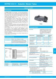
<strong>Thermal</strong>-<strong>Magnetic</strong> <strong>Circuit</strong> <strong>Breaker</strong> <strong>E2215</strong><br />
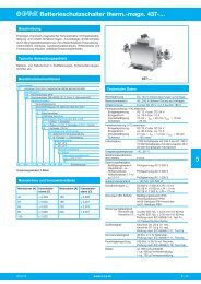
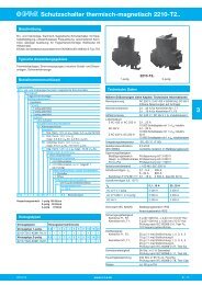
Description<br />
<strong>Thermal</strong>-magnetic circuit breaker mounted on Euro Card for 19“ rack<br />
mounting, with one Euro Card accommodating up to three circuit<br />
breakers. Convenient toggle actuation enables series 2215 additionally<br />
to be used as an ON/OFF switch. A red LED is located in the front<br />
frame of the Euro Card, indicating the switching status of the circuit<br />
breaker (via the auxiliary circuit).<br />
Typical applications<br />
Process control, measuring and control systems, telecommunications<br />
Ordering information for circuit breakers only<br />
Type No.<br />
<strong>E2215</strong><br />
Mounting<br />
1 3 x 1-pole, mounted symmetrically (standard)<br />
2 2 x 1-pole, mounted centrally above and below<br />
3 2 x 1-pole, mounted above and below<br />
4 2 x 1-pole, mounted below and centrally<br />
5 1 x 1-pole, mounted above<br />
6 1 x 1-pole, mounted centrally<br />
7 1 x 1-pole, mounted below<br />
Handle<br />
1 aluminium handle (standard)<br />
LED<br />
1 red LED, DC 24 V (standard)<br />
<strong>Circuit</strong> breaker<br />
Actuator design<br />
L2 moulded toggle<br />
Number of poles<br />
1 single pole protected<br />
Accessories<br />
0 without<br />
Terminal design<br />
P1 blade terminals A6.3-0.8 (standard)<br />
Characteristic curve<br />
01 F1 fast acting: therm. 1.01 x 1.4 I N ;<br />
magn. 2-4 x I N DC (DC only)<br />
02 M1 standard delay: therm. 1.01-1.4 x I N ;<br />
magn. 5-10 x I N DC; magn. 3.5-8 x I N DC<br />
03 T1 delayed: therm. 1.01-1.4 x I N ;<br />
magn. 6-13 x I N AC<br />
07 T3 delayed: therm. 1.01-1.4 x I N ;<br />
magn. 9.5-15.5 x I N AC<br />
Auxiliary contacts<br />
S1 with auxiliary contacts (change over)<br />
Auxiliary contact - terminal design<br />
1 same as main terminals<br />
Current ratings<br />
0.05...10 A<br />
<strong>E2215</strong> 3 1 1 - L2 1 0 - 02 - S1 1 - 0.1 A ordering example<br />
Technical data<br />
<strong>Circuit</strong> <strong>Breaker</strong><br />
Main circuit:<br />
voltage rating<br />
current rating range<br />
<strong>E2215</strong>-...<br />
AC 250 V (50/60 Hz); DC 48 V<br />
0.05...10 A<br />
standard current ratings 0.1 0.2 0.3 0.4 0.5 0.6 A<br />
0.8 1 1.5 2 2.5 3 A<br />
4 5 6 8 10 A<br />
Auxiliary circuit:<br />
voltage rating<br />
AC 250 V/DC 28 V<br />
current rating<br />
1 A<br />
Other data see type 2215<br />
Front plate<br />
Dimensions:<br />
width<br />
4 modules (1 module = 5.08 mm)<br />
height<br />
Material<br />
LED<br />
Max. voltage rating<br />
3 U (1 U = 44.45 mm)<br />
aluminium, anodized<br />
DC 24 V<br />
Select the circuit breakers to above ordering information. For further<br />
information please refer to group 2.<br />
It is possible to fit circuit breakers of mixed current ratings on the<br />
Euro Card.<br />
Please add „<strong>Circuit</strong> breakers to be mounted on Euro Card“ to the<br />
circuit breaker designation when ordering so that the applicable suffix<br />
number for the special version (<strong>E2215</strong>-...-L2..) can be determined .<br />
19“ racks may also be fitted with one or two circuit breakers by the<br />
customer, using industry standard components such as base plates,<br />
front plates with handle, sockets. Connection by means of blade<br />
terminals 6.3x0.8 mm.<br />
7<br />
Issue C<br />
www.e-t-a.com<br />
7 - 61
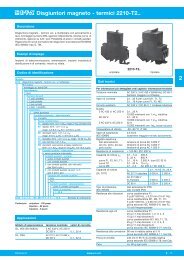
<strong>Thermal</strong>-<strong>Magnetic</strong> <strong>Circuit</strong> <strong>Breaker</strong> <strong>E2215</strong><br />
Dimensions<br />
Sockets for Euro Cards<br />
ON<br />
OFF<br />
ON<br />
OFF<br />
ON<br />
OFF<br />
unit I (GI)<br />
unit III (GIII)<br />
Terminal selection<br />
unit II (GII)<br />
R1<br />
R2<br />
R3<br />
174<br />
6.85<br />
multi-pin connector<br />
LED<br />
100<br />
3.94<br />
X<br />
I<br />
4 TE<br />
3 U<br />
The following sockets may be used with single pole circuit<br />
breakers:<br />
0Z041Z000004<br />
24/7-pole mixed socket to DIN 41612 - form M.<br />
Connection: 7-pole for 6.3x0.8 mm connectors<br />
and 24-pole midi-wire wrap posts (1 x 1 mm).<br />
84.9<br />
12.4<br />
.488<br />
3.34<br />
20 10.1<br />
.787 .398<br />
blade terminals<br />
DIN46244 A6.3x0.8<br />
(QC .250)<br />
7<br />
GI<br />
GII<br />
GIII<br />
GI<br />
GII<br />
GIII<br />
12<br />
11<br />
14<br />
12<br />
11<br />
14<br />
12<br />
11<br />
14<br />
2<br />
1<br />
2<br />
1<br />
2<br />
1<br />
applicable to all circuit breakers GI to GIII<br />
line 1<br />
0 I<br />
22<br />
26<br />
30<br />
view X<br />
d<br />
12<br />
11<br />
I ><br />
2<br />
OFF position<br />
b z<br />
2<br />
d4<br />
b4 +<br />
4<br />
LED GI<br />
6<br />
d10<br />
8<br />
b10 +<br />
10<br />
LED GII<br />
12 d16<br />
14 b16 +<br />
16<br />
LED GIII<br />
20<br />
24<br />
28<br />
32<br />
0 I<br />
wiring diagram for<br />
LED-display<br />
line 1<br />
R1<br />
R2<br />
R3<br />
11<br />
14 12 14<br />
I ><br />
2<br />
ON position<br />
LED<br />
z4 z10 z16<br />
Connection of the Euro Card DIN 41612 with socket type H7/F24-F413.173<br />
Connector of the 19” rack to DIN 41494<br />
Internal connection diagrams<br />
8 10<br />
.315 .394<br />
ø2.8<br />
.110<br />
10.1<br />
.398<br />
84.9<br />
3.34<br />
blade terminals<br />
DIN 46244 A2.8x0.8<br />
(QC. 110)<br />
95<br />
3.74<br />
90<br />
3.54<br />
blade terminals<br />
DIN 46244 A6.3x0.8<br />
(QC .250)<br />
20 10<br />
.787 .394<br />
6.5<br />
.256<br />
5.08<br />
.200<br />
7.62<br />
.300<br />
5.08<br />
.200<br />
5.62<br />
.221<br />
7x5.08=35.56<br />
7x.200=1.40<br />
6x5.08=30.48<br />
6x.200=1.20<br />
5.62<br />
.221<br />
84.9<br />
3.34<br />
12.4<br />
.488<br />
14.8<br />
.583<br />
12.4<br />
.488<br />
20<br />
.787<br />
2.9<br />
.114<br />
ø1<br />
.039<br />
22 10<br />
.866 .394<br />
8.17 6x5.08=30.48 7x5.08=35.56<br />
.322 6x.200=1.20 7x.200=1.40<br />
5.08 7.62 5.08<br />
.200 .300<br />
.200<br />
ø2.8<br />
.110<br />
2.9<br />
.114<br />
6.5<br />
.256<br />
90<br />
3.54<br />
95<br />
3.74<br />
0Z041Z000007<br />
24/7-pole mixed socket to DIN 41612 - form M.<br />
Connection: 7-pole for 6.3x0.8 mm connectors<br />
and 24-pole for 2.8x0.8 mm connectors.<br />
14.8<br />
.583<br />
0Z041Z000005<br />
A 15-pole socket to DIN 41612, form H, for 6.3x0.8 mm<br />
connectors is required in addition to the socket mentioned above,<br />
if two double pole or two three pole circuit breakers are fitted<br />
on one Euro Card.<br />
8.17<br />
.322<br />
ø2.8<br />
.110<br />
14x5.08=71.12<br />
14x.200=2.80<br />
blade terminals<br />
DIN46244 A6.3x0.8<br />
(QC .250)<br />
5.08<br />
.200<br />
This is a metric design and millimeter dimensions take precedence ( mm )<br />
inch<br />
All dimensions without tolerances are for reference only. In the interest of improved design,<br />
performance and cost effectiveness the right to make changes in these specifications<br />
without notice is reserved.Product markings may not be exactly as the ordering codes.<br />
Errors and omissions excepted.<br />
6.5<br />
.256<br />
90<br />
3.54<br />
95<br />
3.74<br />
14.8<br />
.583<br />
7 - 62 www.e-t-a.com<br />
Issue C