H40 AbsoluteShock Proof Encoder - Ä°maj Teknik
H40 AbsoluteShock Proof Encoder - Ä°maj Teknik
H40 AbsoluteShock Proof Encoder - Ä°maj Teknik

Create successful ePaper yourself
Turn your PDF publications into a flip-book with our unique Google optimized e-Paper software.
<strong>H40</strong> Absolute Shock <strong>Proof</strong> <strong>Encoder</strong><br />
Built to the same rugged standards as the <strong>H40</strong> Incremental Heavy Duty encoder,<br />
this unit features an absolute encoder output up to 13 bits of resolution. Designed<br />
to take the rigors of physically demanding environments, the <strong>H40</strong> has a heavy-duty<br />
housing, a 100+ pound bearing, and internal shock absorbers. When you need<br />
absolute position in a really tough environment, the <strong>H40</strong> absolute is what you need.<br />
Electrical Specifications<br />
Reference the H25 Absolute <strong>Encoder</strong>, page 34<br />
Mechanical & Environmental Specs<br />
Reference the <strong>H40</strong> Incremental <strong>Encoder</strong>, pages 28-29<br />
<strong>H40</strong> Absolute <strong>Encoder</strong> Ordering Options FOR ASSISTANCE CALL 800-350-2727<br />
Use this diagram, working from left to right to construct your model number (example: <strong>H40</strong>A-12GC-28V/V-CW-SC-UL).<br />
All notes and tables referred to can be found on pages 50-51.<br />
<strong>H40</strong><br />
TYPE:<br />
H = Heavy Duty;<br />
40 = 4.00" Square<br />
NUMBER OF BITS:<br />
12 = 12-Bits, 4096 counts per turn<br />
13 = 13 Bits, 8192 counts per turn<br />
HMT - Consult factory<br />
(Excess gray codes and BCD<br />
available–consult factory)<br />
HOUSING<br />
CONFIGURATION:<br />
A = Base Mounted Feet<br />
B = No Mounting Feet<br />
CODE TYPE:<br />
GC = Gray Code<br />
NB = Natural Binary<br />
BCD = Binary Coded Decimal<br />
X = Excess gray code<br />
VOLTAGE/OUTPUT:<br />
28V/V = 5-28Vin/out<br />
28V/5 = 5-28Vin/5Vout<br />
28V/OC = 5-28Vin/OCout<br />
A1 =4-20mA<br />
A2 =0-10V<br />
S1 = RS422 Asynchronous<br />
Serial Interface<br />
S3 =Serial Synchronous<br />
Interface (See note 5<br />
and page 40 for SSI)<br />
OUTPUT TERMINATION:<br />
SC = Side Conduit<br />
EC = End Conduit; Conduit uses 1/2-14<br />
NPSF (dryseal) straight pipe threads;<br />
EM18 = MS3102R18-1P<br />
DIRECTION CONTROL:<br />
CW = Clockwise increasing count<br />
CCW = Counter clockwise<br />
increasing count<br />
SPECIAL<br />
FEATURES:<br />
S= Special features specified<br />
on purchase order<br />
(consult factory)<br />
See note 6<br />
CERTIFICATION:<br />
UL = UL Explosion <strong>Proof</strong> rating, only<br />
available with SC termination<br />
Copyright © 2007 by BEI Industrial <strong>Encoder</strong>s | 1-800-ENCODER | www.beiied.com
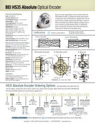
BEI H25 Absolute Optical <strong>Encoder</strong><br />
Electrical Specifications<br />
Code: 12 or 13 bits NB or GC; excess gray and BCD available<br />
Counts Per Shaft Turn: 4096 or 8192<br />
Count Transition Accuracy: ± 1/2 bit maximum<br />
Supply Voltage: 5 – 28 VDC<br />
Current Requirements: 120 mA typical<br />
Output Formats: Parallel: Gray Code, Natural Binary and<br />
Binary Coded Decimal; Serial: Serial Synchronous Interface<br />
(SSI) compatible; Analog: 4-20 mA, 0-10V<br />
Voltage/Output: (see note 5)<br />
28V/V: Line Driver, 5–28 VDC in, Vout = Vin<br />
28V/5: Line Driver, 5–28 VDC in, Vout = 5 VDC<br />
28V/OC: Open Collector, 5–28 VDC in OCout<br />
SSI: See page 40<br />
Protection Level: Reverse, overvoltage and output short circuit<br />
protection (7272 only)<br />
Frequency Response: 100kHz (1200 RPM for 12-bits, 600<br />
RPM for 13-bits)<br />
Output Termination Pinouts: See table page 41<br />
Mechanical & Environmental Specs<br />
Reference the H25 Incremental <strong>Encoder</strong>, pages 16-17<br />
Connector<br />
MS3112E14-19P, 19–pin connector on encoder body, mates to<br />
MS3116F14-19S (or equivalent)<br />
NOTES & TABLES: All notes and tables referred to in the text<br />
can be found on pages 50.<br />
Figure 1 Gray Code<br />
ETC. THRU LSB (GO)<br />
G6<br />
G7<br />
G8<br />
G9<br />
G10<br />
MSB (G11)<br />
CW Increasing Count Viewing Shaft<br />
ONE REVOLUTION<br />
Certifications<br />
MS STYLE<br />
CONNECTOR<br />
Ø 2.52<br />
MAX<br />
0.3747<br />
Ø<br />
0.3745<br />
1.30 (SM 14/19)<br />
Ø<br />
1.2500<br />
1.2495<br />
EM CONNECTOR<br />
POSITION<br />
SM CONNECTOR<br />
POSITION<br />
0.255<br />
2.50<br />
0.30<br />
0.88 ± 0.03<br />
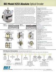
Long considered the industry standard for shafted incremental<br />
encoders, the Model H25 is now available in an absolute version<br />
with up to 13 Bits of resolution. It incorporates many of the great<br />
standard features of the incremental version, including: EMI<br />
shielding, 40-lb ABEC 7 bearings, matched thermal coefficients on<br />
critical components, and custom optics. This encoder features a 12<br />
or 13 Bit absolute parallel gray code output, a selection line for<br />
count direction, and an output latch as standard. Output is standard<br />
gray code with options for natural binary or SSI compatible<br />
signals. Signals can be provided in either a single-ended multivoltage<br />
line driver (TTL compatible when provided with 5 volts) or<br />
as an open-collector style of output. Typical applications include<br />
dam gate control, cranes, telescopes, tool changers, and robotics.<br />
EN 55011 and EN 61000-6-2<br />
0.300<br />
0.100<br />
.100 MIN<br />
Ø 2.275<br />
1.38<br />
Ø 2.500<br />
1.2500<br />
Ø<br />
1.2495<br />
See Regulatory Information on pages<br />
47– 49 for further certification details.<br />
H25D - Square Flange H25E - 2.50 Servo Mount H25G - 2.62 Dia Servo Mount<br />
0.125<br />
0.125<br />
2.500<br />
Ø<br />
2.498<br />
Ø 2.625<br />
NOTE: SHAFT SEAL NOT<br />
AVAILABLE ON H25 G<br />
Figure 2 Natural Binary<br />
CW Increasing Count Viewing Shaft<br />
ETC. THRU LSB (2 0 )<br />
ONE REVOLUTION<br />
2.064 TYP<br />
1.032 0.21 R<br />
30°<br />
30°<br />
2 6<br />
2 7<br />
2 8<br />
2 9<br />
2 10<br />
MSB (2 11 )<br />
2.650<br />
SQUARE<br />
Ø 0.218 4 HOLES<br />
(Ø 2.919 B.C. REF)<br />
0.34<br />
F4<br />
6-32 UNC-2B<br />
0.250 Min. Deep<br />
3 places equally spaced<br />
on a Ø 2.00 bolt circle.<br />
F1<br />
10-32 UNF-2B<br />
0.188 Min. Deep<br />
3 places equally spaced<br />
on a Ø 1.875 bolt circle.<br />
TOLERANCES: .XX = ± 0.01, .XXX = ± 0.005<br />
H25 Absolute <strong>Encoder</strong> Ordering Options FOR ASSISTANCE CALL 800-350-2727<br />
Use this diagram, working from left to right to construct your model number (example: H25E-F4-SS-12GC-28V/V-CW-SM14/19).<br />
All notes and tables referred to can be found on pages 50-51.<br />
H25<br />
X =<br />
Express<br />
<strong>Encoder</strong><br />
TYPE:<br />
Heavy Duty<br />
2.5 inch Dia.<br />
HOUSING :<br />
D = Square Flange<br />
E = 2.5 inch dia.<br />
servo mount<br />
G = 2.62 inch dia.<br />
servo mount<br />
See dimensions<br />
FACE<br />
MOUNTS:<br />
F1<br />
F4<br />
See note 1<br />
SHAFT SEAL<br />
CONFIGURATION:<br />
SS = Shaft Seal<br />
See note 2<br />
NUMBER OF BITS:<br />
12 = 12-Bits, 4096 counts per turn<br />
13 = 13 Bits, 8192 counts per turn<br />
(Excess gray codes and BCD<br />
available–consult factory<br />
CODE TYPE:<br />
GC = Gray Code<br />
NB = Natural Binary<br />
BCD = Binary<br />
Coded Decimal<br />
X = Excess<br />
gray code<br />
VOLTAGE/OUTPUT:<br />
28V/V = 5-28 V in/out<br />
28V/5 = 5-28 V in /5V out<br />
28V/OC = 5-28 V in /OC out<br />
A1 = 4-20mA; A2 = 0-10V<br />
SI = RS - 422 Serial<br />
Asynchronous<br />
S3 = Serial<br />
Synchronous Interface<br />
See note 5 and page 40 for SSI<br />
Copyright © 2007 by BEI Industrial <strong>Encoder</strong>s | 1-800-ENCODER | www.beiied.com<br />
OUTPUT<br />
TERMINATION<br />
LOCATION:<br />
E = End<br />
S = Side<br />
DIRECTION<br />
CONTROL:<br />
CW = Clockwise<br />
increasing count<br />
CCW = Counter clockwise<br />
increasing count<br />
EXPRESS ENCODERS ® Items highlighted with are standard Express <strong>Encoder</strong>s and ship in one to three days.<br />
SPECIAL FEATURES:<br />
S = Special features<br />
specified on purchase<br />
order (consult factory)<br />
See note 6<br />
TERMINATION TYPE:<br />
M14/19 = 19 pin connector<br />
CS= Cable with gland seal<br />
Cable length specified in inches<br />
(i.e. C18 = Pigtail 18” long)<br />
See page 41
BEI <strong>H40</strong> Shock <strong>Proof</strong> Optical <strong>Encoder</strong><br />
The <strong>H40</strong> is an ultra heavy duty encoder<br />
whose internal structure is totally isolated<br />
from severe shock and shaft loading<br />
conditions. The optics and electronics are<br />
supported in shock absorbing material within<br />
the heavy cast outer housing. The encoder<br />
shaft is flexibly coupled to the high load<br />
capacity bearings and shaft assembly,<br />
which is carried in the outer<br />
housing. The entire bearing<br />
assembly is field-removable to<br />
permit proper shaft support while<br />
pressing pulleys, gears, etc. onto the shaft.<br />
An Underwriters Laboratories listed version of<br />
this model is available.<br />
<strong>H40</strong> Shock <strong>Proof</strong> Ordering Options FOR ASSISTANCE CALL 800-350-2727<br />
Use this diagram, working from left to right to construct your model number (example: <strong>H40</strong>A-2000-ABZC-28V/V-SC-UL).<br />
All notes and tables referred to can be found on pages 50-51.<br />
<strong>H40</strong><br />
TYPE:<br />
H = Heavy Duty;<br />
40 = 4.00" Square<br />
HOUSING<br />
CONFIGURATION:<br />
A = Base Mounted Feet<br />
B = No Mounting Feet<br />
CYCLES PER TURN:<br />
Enter Cycles<br />
See table 2<br />
NO. OF CHANNELS:<br />
A = Single Channel<br />
AB = Dual Quad. Ch.<br />
ABZ = Dual with Index<br />
AZ = Single with Index<br />
See note 3<br />
COMPLEMENTS:<br />
C = Complementary<br />
Outputs,<br />
Blank = None<br />
See note 4<br />
VOLTAGE/OUTPUT:<br />
15V/V = 5-15 Vin/out<br />
28V/V = 5-28Vin/out<br />
28V/5 = 5-28Vin/5Vout<br />
28V/OC = 5-28Vin/OCout<br />
See note 5<br />
OUTPUT TERMINATION:<br />
SC = Side Conduit<br />
EC = End Conduit; Conduit uses 1/2-<br />
14 NPSF (dryseal) straight pipe<br />
threads;<br />
EM16 = MS3102R16S-1P<br />
EM18 = MS3102R18-1P,<br />
See table A on next page<br />
CERTIFICATION:<br />
UL = UL Explosion<br />
<strong>Proof</strong> rating, only<br />
available with SC<br />
termination<br />
SPECIAL<br />
FEATURES:<br />
S= Special<br />
features specified<br />
on purchase order<br />
(consult factory)<br />
See note 6<br />
Certifications<br />
The <strong>H40</strong> Shock <strong>Proof</strong> <strong>Encoder</strong> is available with the following certifications:<br />
EN 55011 and<br />
EN 61000-6-2<br />
U.S. Standards Class I,<br />
Group D, Division 1<br />
C<br />
Canadian Standards Class I,<br />
Group D, Division 1<br />
See Regulatory Information on pages 47– 49 for<br />
further certification details.<br />
Copyright © 2007 by BEI Industrial <strong>Encoder</strong>s | 1-800-ENCODER | www.beiied.com
Incremental <strong>Encoder</strong>s<br />
<strong>H40</strong>A<br />
Ø .281 (4)<br />
<strong>H40</strong>B<br />
INCREMENTAL<br />
TERMINAL FUNCTION<br />
A CHANNEL A<br />
B<br />
B<br />
Z<br />
Z<br />
V +VDC<br />
G GROUND (0V)<br />
CG CASE GROUND<br />
A<br />
A<br />
B<br />
B<br />
Z<br />
Z<br />
S SPARE*<br />
*or SELECT on Dual Count<br />
encoders<br />
Ø 3.56<br />
TOLERANCES:<br />
.XX = ± 0.01,<br />
.XXX = ±0.005<br />
8-BIT ABSOLUTE*<br />
GRAY NATURAL TERMINAL<br />
CODE BINARY NUMBER<br />
G0 2 0 1<br />
G1 2 1 2<br />
G2 2 2 3<br />
G3 2 3 4<br />
G4 2 4 5<br />
G5 2 5 6<br />
G6 2 6 7<br />
G7 2 7 8<br />
SPARE 9<br />
SPARE 10<br />
LATCH 11<br />
INTERROGATE 12<br />
SPARE 13<br />
+VDC 14<br />
0V (COMMON) 15<br />
CASE GROUND 16<br />
Latch and Interrogate are optional<br />
*For higher resolutions, see<br />
Absolute Options pages 40-41<br />
Ø 0.6248<br />
0.6244<br />
Field Replaceable Coupling and Bearing Assembly<br />
Rear<br />
View<br />
Table A Output Functions Figure 1<br />
BEARING RATING LIFE (HOURS)<br />
S<br />
1/4-20 UNC-2B<br />
0.50 DEEP (4) ON<br />
A Ø 3.0 B.C.<br />
A B Z V G CG A B Z S<br />
Bearing Life vs. Speed<br />
at Various Radial Loads<br />
SPEED (RPM)<br />
A<br />
Mechanical Specifications<br />
Shaft Diameter: 5/8" nominal<br />
Flats On Shaft: Two flats, 0.75" long X 0.30" deep at 90º<br />
Shaft Loading/Bearing Life: Refer to Figure 1<br />
Shaft Runout: 0.001" T.I.R. at mid-point of shaft<br />
Starting Torque at 25° C: 10.0 in-oz (max)<br />
Bearings: Class 52100 SAE high carbon steel<br />
Shaft Material: 1070 carbon steel, 303 stainless steel optional<br />
Enclosure: Die cast aluminum, hard anodized with dichromate<br />
sealed finish. Shaft seals and sealed bearings are standard to<br />
achieve environmental ratings.<br />
Maximum RPM: 10,000 RPM (see Frequency Response, below)<br />
Coupling Windup: The <strong>H40</strong> uses an internal coupling. Windup<br />
error (degrees) = α X 7.5 X 10 -4 rad/sec 2<br />
where α= angular acceleration in rad/sec 2<br />
Weight: Approx 9 lbs<br />
Electrical Specifications<br />
Code: Incremental or Absolute (see Absolute options,<br />
pgs 40-41)<br />
Output Format: 2 channels in quadrature, 1/2 cycle index gated<br />
with negative B channel or Absolute to 13 bits<br />
Cycles per Shaft Turn: 1 to 72,000 (see table 2).<br />
For resolutions above 3,600 see interpolation options on pages<br />
32 and 33); Absolute to 8192 counts per turn<br />
Supply Voltage: 5 to 28 VDC available<br />
Current Requirements: 100 mA typical +output load, 250 mA (max)<br />
Voltage/Output: (see note 5)<br />
15V/V: Line Driver, 5–15 VDC in, Vout = Vin<br />
28V/V: Line Driver, 5–28 VDC in, Vout = Vin<br />
28V/5: Line Driver, 5–28 VDC in, Vout = 5 VDC<br />
28V/OC: Open Collector, 5 – 28 VDC in, OCout<br />
Protection Level: Reverse, overvoltage and output short circuit<br />
(see note 5)<br />
Frequency Response: 100 KHz, up tp 1 MHz with<br />
interpolation option (see note 7)<br />
Output Terminations: See Table A, this page<br />
Termination Type: Compression type, UL recognized. Accepts<br />
AWG 14 to 22, stranded wire, strip 1/4"<br />
Note: Consult factory for other electrical options<br />
Environmental Specifications<br />
Enclosure Rating: NEMA 4 X & 6 (IP66), outdoor Non-<br />
Hazardous locations, NEMA 4 X & 13 (IP66), indoor Non-<br />
Hazardous locations<br />
Hazardous Area Rating: The optional Underwriters<br />
Laboratories listed version is for use in hazardous locations;<br />
NEMA Enclosure 7. Class 1, Group D, Division 1, NEC Class 2<br />
circuits only<br />
Temperature: Operating, 0º to 70º C; extended temperature<br />
testing available (see note 8, pg 50); 80º C max for UL and CEN<br />
approved units; storage; -25º to 90º C unless extended temperature<br />
option called out<br />
Shock: 200 g's at 11msec<br />
Vibration: 5 to 2000 Hz @ 20 g's<br />
Humidity: 100% RH<br />
NOTES & TABLES: All notes and tables referred to in the text<br />
can be found on pages 50 and 51.<br />
Copyright © 2007 by BEI Industrial <strong>Encoder</strong>s | 1-800-ENCODER | www.beiied.com
40<br />
BEI | Page Absolute Title <strong>Encoder</strong> Options<br />
Parallel Absolute Output<br />
The two most common types of absolute outputs are the Gray Code and the Natural<br />
Binary. Resolution for absolute encoders is expressed in “bits”where each successive<br />
bit increases the resolution by a factor of two. For example, 10 bits = 2 10 =<br />
1024 counts per revolution.<br />
Natural binary code (Figure 1) is constructed so that the code counts up using the<br />
natural sequence of binary counting, i.e. 000, 001, 010, 011, 100 . . etc. The drawback<br />
to using this code sequence is that at several count positions the code will<br />
have transitions on multiple bits simultaneously. Due to the normal variations<br />
caused by gate delays, line impedances, etc. the actual transitions will not occur<br />
simultaneously. Reading data during one of these times could result in an erroneous<br />
reading. This can be overcome by taking multiple readings.<br />
Gray code (Figure 2), by contrast, is designed to avoid the multiple transition problem<br />
entirely. It is specifically constructed so that only one bit will transition at a<br />
time. This ensures that state changes are much less ambiguous to the controller<br />
and is generally considered to be a more robust type of absolute code.<br />
Regardless of the code type, one of the characteristics of absolute encoders is that<br />
they can readily be used for any resolution up to and including their maximum resolution.<br />
For example, a 12 bit encoder can be used at only 8 bits by ignoring (or disconnecting)<br />
the four lowest significant bits (LSB). This enables an installation that<br />
uses multiple absolute encoders to use the same encoder throughout with each<br />
controller using only the bits that it needs.<br />
Figure 1 Natural Binary<br />
2 0<br />
(LSB)<br />
2 1<br />
2 2<br />
Figure 2 Gray Code<br />
G0<br />
(LSB)<br />
G1<br />
G2<br />
G3<br />
2 3 ETC. THRU G7 (MSB)<br />
ETC. THRU 2 7 (MSB)<br />
Ordering 8-Bit Absolutes<br />
For years, we produced encoders with a maximum resolution of 8 bits. Lots<br />
of those old 8 bit encoders are still around. We update them to newer 12 bit<br />
designs on a case-by-case basis. If you have an 8 bit encoder, here is how<br />
that model number was constructed: Direction of Rotation, Count, Code<br />
and Latch designators were inserted between Shaft Seal Configuration<br />
and Voltage/Output as shown below. To specify an equivalent encoder<br />
based on the 12 bit design, please call our Applications Specialists at 800-<br />
ENCODER (800-362-6337) or check our web site at www.beiied.com.<br />
Direction of Rotation: CCW or CW<br />
Count: 8<br />
Code: GC= Gray Code or NB= Natural Binary<br />
Latch: L= Latch or Blank=None<br />
Output Terminations: EM20=MS3102R20-29P or ED25=DB25P;<br />
SM18 = MS3102R18-1P; C18 = Cable, with length specified in<br />
inches. Specify ED25 for Line Driver Outputs.<br />
Example: H25E-F1-SS-CCW-8GC-28V/V-EM20<br />
(one possible encoder configuration with the 8-Bit Absolute Option.)<br />
Serial Synchronous Interface (SSI)<br />
SSI output provides effective synchronization in a closed-loop control system.<br />
A clock pulse train from a controller is used to clock out sensor data: one bit of position<br />
data is transmitted to the controller per one clock pulse received by the sensor.<br />
The use of a differential driver permits reliable transmission of data over long distances<br />
in environments that may be electrically noisy. The encoder utilizes a clock<br />
signal, provided by the user interface, to time the data transmission. Receiving electronics<br />
must include an appropriate receiver as well as line terminating resistors.<br />
Features<br />
•Synchronous transmission<br />
•Transmission lengths to 1000 feet<br />
•Accepts clock rates from 100 KHz to 1.8 MHz<br />
Data Transmission Sequence<br />
1. Output driver of the encoder is a MAX 491 transceiver in transmit mode.<br />
The recommended receiver is a MAX 491 transceiver in receive mode.<br />
2. Controller provides a series of pulses (or differential pulse pairs) on the CLOCK<br />
input lines.<br />
3. On the first HIGH-to-LOW CLOCK transition, the encoder latches its data at the<br />
current position and prepares to transmit.<br />
4. Controller reads data on the falling edge of the next 16 clock cycles.<br />
5. The first bit is a START bit and is always HIGH.<br />
6. Next come 12 data bits beginning with the most significant bit (MSB) and ending<br />
with the least significant bit (LSB). This is followed by three LOW pulses.<br />
7. After the DATA bits, the DATA line goes LOW and remains LOW for a minimum of<br />
30 microseconds between the end of the DATA bits and the beginning of the next<br />
CLOCK series.<br />
Interfacing Long Data Lines<br />
Cable impedance can create a transmission delay, in effect, shifting the phase relationship<br />
between the clock pulse and the data. If this phase shift exceeds 180°,<br />
then the wrong bit position will be sampled by the receiver. As a result, the maximum<br />
allowable clock frequency is a function of the cable length. For 24 AWG,<br />
stranded, 3 pair cable (BEI part number 37048-003 or equivalent) the group delay is<br />
1.36ns/ft. The table below shows the maximum transmission rate allowable as a<br />
function of cable length to ensure a phase shift of less than 90°.<br />
CLOCK, Maximum (kHz) = 92,000 / Cable Length (ft)CW<br />
Cable Length (ft) 50 100 200 300 500 1000<br />
Max Freq (kHz) 1800 900 500 300 200 100<br />
SSI Timing<br />
Ordering SSI<br />
HOW TO SPECIFY SSI OUTPUT IN THE ENCODER MODEL NUMBER:<br />
Use the designation, S3 between the Code Format designation<br />
and the Connector designation.<br />
Example: H25D-SS-12GC-S3-CW-SM18<br />
Copyright © 2007 by BEI Industrial <strong>Encoder</strong>s | 1-800-ENCODER | www.beiied.com
| 41<br />
Absolute <strong>Encoder</strong>s<br />
Single Turn Absolute <strong>Encoder</strong> Options<br />
The tables below are reference for pinouts, connections and operation of BEI’s single turn absolute encoders. These absolute op tions are<br />
available in a wide range of package styles with a variety of outputs. The applicability table below shows which combinations are currently<br />
available. As always, you can call us at 800-350-ASAP (2727) for immediate applications assistance should you have any questions.<br />
Output Code and Terminations (12 & 13 Bit)<br />
PARALLEL CODE<br />
Binary<br />
Natural Coded<br />
Gray Code Binary Decimal<br />
12 Bit 13 Bit 12 Bit 13 Bit<br />
MSB G 11 G 12 2 11 2 12 A 0<br />
G 10 G 11 2 10 2 11 B 0<br />
G 9 G 10 2 9 2 10 C0<br />
G 8 G 9 2 8 2 9 D 0<br />
G 7 G 8 2 7 2 8 A 1<br />
G 6 G 7 2 6 2 7 B 1<br />
G 5 G 6 2 5 2 6 C 1<br />
G 4 G 5 2 4 2 5 D 1<br />
G 3 G 4 2 3 2 4 A 2<br />
G 2 G 3 2 2 2 3 B 2<br />
G 1 G 2 2 1 2 2 C 2<br />
LSB 12 G 0 G 1 2 0 2 1 D 2<br />
LSB 13 G 0 2 0 A 3<br />
0V (CIRCUIT COMMON) 1 B3<br />
DIRECTION CONTROL<br />
CASE GROUND<br />
0 V (CIRCUIT COMMON)<br />
LATCH CONTROL<br />
+V (SUPPLY VOLTAGE)<br />
SHIELD DRAIN<br />
1<br />
Pin P is available for a tri-state option<br />
TERMINATION TYPE<br />
Term<br />
Board<br />
Cable Conn H38 & <strong>H40</strong><br />
WHT/BLK A 1<br />
WHT/BRN B 2<br />
WHT/RED C 3<br />
WHT/ORN D 4<br />
WHT/YEL E 5<br />
WHT/GRN F 6<br />
WHT/BLU G 7<br />
WHT/VIO H 8<br />
WHT/GRY J 9<br />
WHT K 10<br />
GRY/BLK L 11<br />
GRY/BRN M 12<br />
GRY/RED N 13<br />
GRY/ORN P<br />
ORN R 18<br />
GRN S 16<br />
BLK T 15<br />
YEL U 17<br />
RED V 14<br />
BARE —<br />
Output Applicability Table<br />
12 BITS 13 BITS 14/15 12x12 S3 S1 A1 A2<br />
PARALLEL PARALLEL BITS BITS SSI RS422 4–20mA 0–10 V<br />
H25 • • • • • •<br />
H25X • •<br />
HS35 • •<br />
H38 • • • • • • •<br />
<strong>H40</strong> • • • • • • •<br />
HMT25 • • • •<br />
Direction Control: Standard is CW increasing when viewed from the shaft end.<br />
Pin R is normally HI (or N/C) and is pulled up internally to +V. To reverse the count<br />
direction, Pin R must be pulled LO (COMMON ).<br />
Latch control: <strong>Encoder</strong> outputs are active and provide continuous parallel position<br />
information when Pin U is HI (or N/C). Pin U is pulled up internally to +V. When<br />
Pin U is LO (COMMON) the encoder outputs are latched at the logic state that is present<br />
when the latch is applied and will stay latched until Pin U is no longer grounded.<br />
Parallel Code (14 & 15 Bit) 2<br />
M14/19<br />
Gray Code Natural Binary Connector<br />
14 BIT 15 Bit 14 BIT 15 Bit<br />
MSB G 13 G 14 2 13 2 14 A<br />
G 12 G 13 2 12 2 13 B<br />
G 11 G 12 2 11 2 12 C<br />
G 10 G 11 2 10 2 11 D<br />
G 9 G 10 2 9 2 10 E<br />
G 8 G 9 2 8 2 9 F<br />
G 7 G 8 2 7 2 8 G<br />
G 6 G 7 2 6 2 7 H<br />
G 5 G 6 2 5 2 6 J<br />
G 4 G 5 2 4 2 5 K<br />
G 3 G 4 2 3 2 4 L<br />
G 2 G 3 2 2 2 3 M<br />
G 1 G 2 2 1 2 2 N<br />
LSB14 G 0 G 1 2 0 2 1 P<br />
LSB15 DIR G 0 DIR 2 0 R<br />
CONTROL<br />
CONTROL<br />
CASE GROUND<br />
S<br />
OV (CIRCUIT COMMON)<br />
T<br />
LATCH DIR/LATCH LATCH DIR/LATCH U<br />
+V (SUPPLY +V (SUPPLY +V (SUPPLY +V (SUPPLY<br />
VOLTAGE) VOLTAGE) VOLTAGE) VOLTAGE)<br />
V<br />
2<br />
Units Manufactured before April 2007 are LSB Justified.<br />
SSI Output Termination Table<br />
M18 M14/19 CABLE TERM. BOARD<br />
CONN CONN CONN H38 <strong>H40</strong><br />
DATA + A A YEL 4 1<br />
DATA- H B WHT/YEL 7 7<br />
CLOCK+ B C BLU 5 2<br />
CLOCK- I D WHT/BLU 8 8<br />
DIR CONTROL C R ORN 6 3<br />
CASE GROUND G S GRN 1 6<br />
CIRCUIT COMMON F T BLK 2 5<br />
+V SUPPLY VOLTAGE D V RED 3 4<br />
SHIELD DRAIN — — BARE — —<br />
Dir/Latch on 15-Bit <strong>Encoder</strong>s: Due to a limited number of connector pins, either<br />
direction control or latch is available on pin U.<br />
M18 Connector is a MS3102R18-1P, 10-pin connector on the encoder body and mates<br />
to an MS3106F18-1S connector or can be used with a standard cable/connector<br />
assembly, BEI P/N 924-31186-18XX (Where X = 10, 20 or 30 for a 10, 20, or 30 foot<br />
length). This is the preferred connector for SSI output.<br />
M14/19 Connector is a MS3112E14-19P, 19-pin connector on the encoder body and<br />
mates to an MS3116F14-19S or equivalent.<br />
Copyright © 2007 by BEI Industrial <strong>Encoder</strong>s | 1-800-ENCODER | www.beiied.com