LANTEK User Manual - Ideal Industries
LANTEK User Manual - Ideal Industries LANTEK User Manual - Ideal Industries
Chapter 5 Fiber Optics Cable Field Calibration and Testing METHOD ‘A’ Calibration Setup The Method ‘A’ calibration uses two launch cables and a set of couplers. This is the recommended calibration procedure for FIBERTEK, as it does not require disconnecting the launch cables from the modules. Test Setup Figure 5-3: Method 'A' Calibration Setup The Method ‘A’ test setup is best used for long fiber links where the majority of the attenuation is caused by the cable itself, not the connectors. With this configuration, the calibration reference plane is at the patch panel and work area outlet. The measurement taken will include the loss of the fiber optic cable (including inline splices and couplers) and the individual connector at each end of the link (one pair). Since there is only one pair of connectors included in this measurement, the overall loss values may be lower than one would expect, particularly when this setup is used to test very short cables. When used on long links of over 1km (multimode) or 4km (single mode) the loss of the connectors is small compared with the fiber, making this an acceptable setup for longer links. Use this configuration when knowing the loss of the optical fiber is more important than knowing the total link loss. Figure 5-4: Method ‘A’ Test Setup 5-5
Chapter 5 Fiber Optics Cable Field Calibration and Testing METHOD ‘A’ ALTERNATE Test Setup The Method ‘A’ Alternate test configuration makes it possible to use a dual fiber test system while measuring the actual loss of all the connections and fiber optic cable. By using the ‘A’ Method for calibration and adding a new test jumper for testing, the Method ‘A’ Alternate is useful for testing short links where the connectors make up a large portion of the link attenuation. Figure 5-5: Method 'A' Alternate Test Setup Recommended Setup Calibration Method ‘A’ & Test Method ‘A’ Alternate 1. Following a successful field calibration as described in Method ‘A’, disconnect the Remote Handset launch cables from the couplers. 2. Connect another set of launch cables to the Display Handset launch cables. You should have two sets of launch cables connected to the Display Handset and one set connected to the Remote Handset. 5-6
- Page 40 and 41: Chapter 2 Test Setup Procedures Edi
- Page 42 and 43: Chapter 2 Test Setup Procedures ACT
- Page 44 and 45: Chapter 3 Structured Cable Field Ca
- Page 46 and 47: Chapter 3 Structured Cable Field Ca
- Page 48 and 49: Chapter 3 Structured Cable Field Ca
- Page 50 and 51: Chapter 3 Structured Cable Field Ca
- Page 52 and 53: Chapter 3 Structured Cable Field Ca
- Page 54 and 55: Chapter 3 Structured Cable Field Ca
- Page 56 and 57: Chapter 3 Structured Cable Field Ca
- Page 58 and 59: Chapter 3 Structured Cable Field Ca
- Page 60 and 61: Chapter 3 Structured Cable Field Ca
- Page 62 and 63: Chapter 3 Structured Cable Field Ca
- Page 64 and 65: Chapter 3 Structured Cable Field Ca
- Page 66 and 67: Chapter 3 Structured Cable Field Ca
- Page 68 and 69: Chapter 3 Structured Cable Field Ca
- Page 70 and 71: Chapter 3 Structured Cable Field Ca
- Page 72 and 73: Chapter 3 Structured Cable Field Ca
- Page 74 and 75: Chapter 3 Structured Cable Field Ca
- Page 76 and 77: Chapter 3 Structured Cable Field Ca
- Page 78 and 79: Chapter 3 Structured Cable Field Ca
- Page 80 and 81: Chapter 3 Structured Cable Field Ca
- Page 82 and 83: CHAPTER 4 COAX CABLE FIELD CALIBRAT
- Page 84 and 85: Chapter 4 Coax Cable Field Calibrat
- Page 86 and 87: CHAPTER 5 FIBER OPTICS CABLE FIELD
- Page 88 and 89: Chapter 5 Fiber Optics Cable Field
- Page 92 and 93: Chapter 5 Fiber Optics Cable Field
- Page 94 and 95: Chapter 5 Fiber Optics Cable Field
- Page 96 and 97: Chapter 5 Fiber Optics Cable Field
- Page 98 and 99: Chapter 5 Fiber Optics Cable Field
- Page 100 and 101: Chapter 6 Fiber Optics Diagnostics
- Page 102 and 103: Chapter 6 Fiber Optics Diagnostics
- Page 104 and 105: Chapter 6 Fiber Optics Diagnostics
- Page 106 and 107: Chapter 6 Fiber Optics Diagnostics
- Page 108 and 109: Chapter 6 Fiber Optics Diagnostics
- Page 110 and 111: Chapter 6 Fiber Optics Diagnostics
- Page 112 and 113: CHAPTER 7 LANTEK REPORTER SOFTWARE
- Page 114 and 115: Chapter 7 LANTEK REPORTER Software
- Page 116 and 117: Chapter 7 LANTEK REPORTER Software
- Page 118 and 119: Chapter 7 LANTEK REPORTER Software
- Page 120 and 121: Chapter 7 LANTEK REPORTER Software
- Page 122 and 123: Chapter 7 LANTEK REPORTER Software
- Page 124 and 125: Chapter 7 LANTEK REPORTER Software
- Page 126 and 127: Chapter 7 LANTEK REPORTER Software
- Page 128 and 129: Chapter 7 LANTEK REPORTER Software
- Page 130 and 131: Chapter 7 LANTEK REPORTER Software
- Page 132 and 133: Chapter 7 LANTEK REPORTER Software
- Page 134 and 135: Chapter 7 LANTEK REPORTER Software
- Page 136 and 137: Chapter 7 LANTEK REPORTER Software
- Page 138 and 139: Chapter 7 LANTEK REPORTER Software
Chapter 5<br />
Fiber Optics Cable Field Calibration and Testing<br />
METHOD ‘A’<br />
Calibration Setup<br />
The Method ‘A’ calibration uses two launch cables and a set of couplers. This is the<br />
recommended calibration procedure for FIBERTEK, as it does not require disconnecting<br />
the launch cables from the modules.<br />
Test Setup<br />
Figure 5-3: Method 'A' Calibration Setup<br />
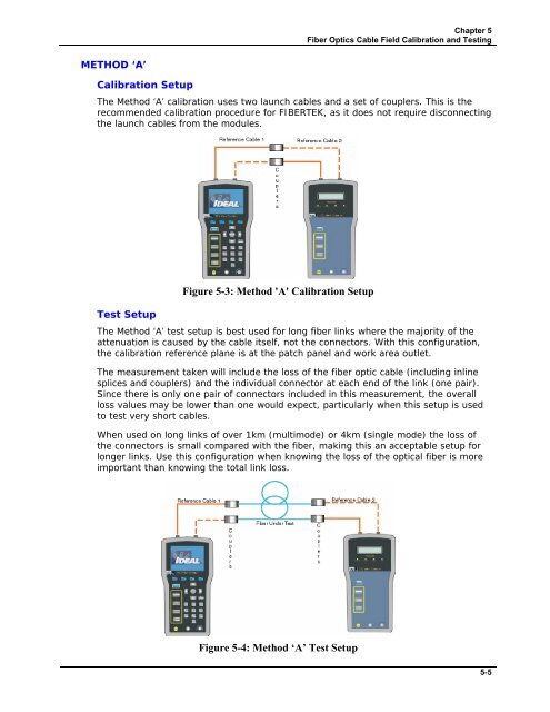
The Method ‘A’ test setup is best used for long fiber links where the majority of the<br />
attenuation is caused by the cable itself, not the connectors. With this configuration,<br />
the calibration reference plane is at the patch panel and work area outlet.<br />
The measurement taken will include the loss of the fiber optic cable (including inline<br />
splices and couplers) and the individual connector at each end of the link (one pair).<br />
Since there is only one pair of connectors included in this measurement, the overall<br />
loss values may be lower than one would expect, particularly when this setup is used<br />
to test very short cables.<br />
When used on long links of over 1km (multimode) or 4km (single mode) the loss of<br />
the connectors is small compared with the fiber, making this an acceptable setup for<br />
longer links. Use this configuration when knowing the loss of the optical fiber is more<br />
important than knowing the total link loss.<br />
Figure 5-4: Method ‘A’ Test Setup<br />
5-5


