LANTEK User Manual - Ideal Industries
LANTEK User Manual - Ideal Industries LANTEK User Manual - Ideal Industries
Chapter 3 Structured Cable Field Calibration and Testing The following troubleshooting tips identify typical cable conditions and their corresponding screen plots. Condition Open, Near End Short, Near End Open, Far End Short, Far End Split Pair Cable segment with higher than nominal impedance Cable segment with lower than nominal impedance Level Plot, much higher than the known cable NVP No distinct upswing or downswing at the Far End TDR Plot Indication Upswing develops early. In comparison to good cable pairs, this pair appears shorter in length. Downswing develops early. In comparison to good cable pairs, this pair appears shorter in length. Fully developed upswing at the Far End. Fully developed downswing at the Far End. 20% to 30% rise in relative impedance at the split with a corresponding drop in impedance where the pair is reconnected. Peak in the level area of the plot. Dip in the level area of the plot. Wrong cable type selected, or wrong cable type installed. Matched terminator attached to the cable. The pair appears to have a very long length. STORING, RETRIEVING, AND DELETING TDR RESULTS Storing a Graph The TDR results can be stored in the Current Job. 1. Press the UP/DOWN ARROW keys to select the desired cable pair graph. 2. Press SHIFT key to save/print. 3. Select . The Save Test screen appears. Press SHIFT to bring up the “Save As” or “Rename” selection if the test has already been stored. 4. The test name is automatically assigned. If a different name is desired, press DELETE to change the highlighted character(s). 5. When you have entered the name, press ENTER to accept the changes and return to the ready screen. Retrieving or Deleting a Graph For detailed instructions regarding retrieving or deleting stored TDR results, refer to Viewing or Deleting Stored Autotest Results. 3-38
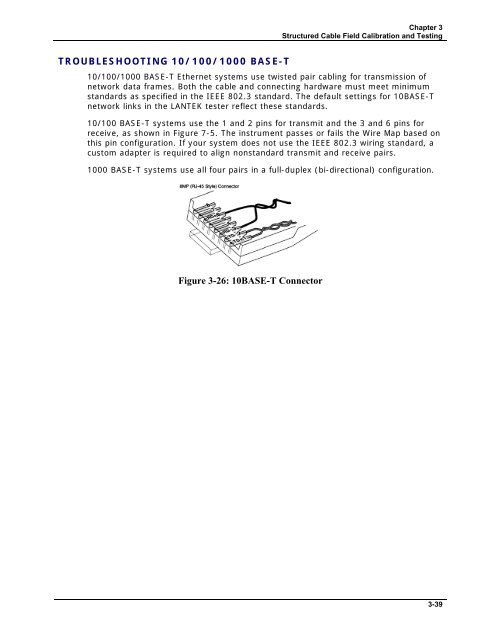
Chapter 3 Structured Cable Field Calibration and Testing TROUBLESHOOTING 10/100/1000 BASE-T 10/100/1000 BASE-T Ethernet systems use twisted pair cabling for transmission of network data frames. Both the cable and connecting hardware must meet minimum standards as specified in the IEEE 802.3 standard. The default settings for 10BASE-T network links in the LANTEK tester reflect these standards. 10/100 BASE-T systems use the 1 and 2 pins for transmit and the 3 and 6 pins for receive, as shown in Figure 7-5. The instrument passes or fails the Wire Map based on this pin configuration. If your system does not use the IEEE 802.3 wiring standard, a custom adapter is required to align nonstandard transmit and receive pairs. 1000 BASE-T systems use all four pairs in a full-duplex (bi-directional) configuration. Figure 3-26: 10BASE-T Connector 3-39
- Page 30 and 31: Chapter 2 Test Setup Procedures PAC
- Page 32 and 33: Chapter 2 Test Setup Procedures TEM
- Page 34 and 35: Chapter 2 Test Setup Procedures Tab
- Page 36 and 37: Chapter 2 Test Setup Procedures Sav
- Page 38 and 39: Chapter 2 Test Setup Procedures OTH
- Page 40 and 41: Chapter 2 Test Setup Procedures Edi
- Page 42 and 43: Chapter 2 Test Setup Procedures ACT
- Page 44 and 45: Chapter 3 Structured Cable Field Ca
- Page 46 and 47: Chapter 3 Structured Cable Field Ca
- Page 48 and 49: Chapter 3 Structured Cable Field Ca
- Page 50 and 51: Chapter 3 Structured Cable Field Ca
- Page 52 and 53: Chapter 3 Structured Cable Field Ca
- Page 54 and 55: Chapter 3 Structured Cable Field Ca
- Page 56 and 57: Chapter 3 Structured Cable Field Ca
- Page 58 and 59: Chapter 3 Structured Cable Field Ca
- Page 60 and 61: Chapter 3 Structured Cable Field Ca
- Page 62 and 63: Chapter 3 Structured Cable Field Ca
- Page 64 and 65: Chapter 3 Structured Cable Field Ca
- Page 66 and 67: Chapter 3 Structured Cable Field Ca
- Page 68 and 69: Chapter 3 Structured Cable Field Ca
- Page 70 and 71: Chapter 3 Structured Cable Field Ca
- Page 72 and 73: Chapter 3 Structured Cable Field Ca
- Page 74 and 75: Chapter 3 Structured Cable Field Ca
- Page 76 and 77: Chapter 3 Structured Cable Field Ca
- Page 78 and 79: Chapter 3 Structured Cable Field Ca
- Page 82 and 83: CHAPTER 4 COAX CABLE FIELD CALIBRAT
- Page 84 and 85: Chapter 4 Coax Cable Field Calibrat
- Page 86 and 87: CHAPTER 5 FIBER OPTICS CABLE FIELD
- Page 88 and 89: Chapter 5 Fiber Optics Cable Field
- Page 90 and 91: Chapter 5 Fiber Optics Cable Field
- Page 92 and 93: Chapter 5 Fiber Optics Cable Field
- Page 94 and 95: Chapter 5 Fiber Optics Cable Field
- Page 96 and 97: Chapter 5 Fiber Optics Cable Field
- Page 98 and 99: Chapter 5 Fiber Optics Cable Field
- Page 100 and 101: Chapter 6 Fiber Optics Diagnostics
- Page 102 and 103: Chapter 6 Fiber Optics Diagnostics
- Page 104 and 105: Chapter 6 Fiber Optics Diagnostics
- Page 106 and 107: Chapter 6 Fiber Optics Diagnostics
- Page 108 and 109: Chapter 6 Fiber Optics Diagnostics
- Page 110 and 111: Chapter 6 Fiber Optics Diagnostics
- Page 112 and 113: CHAPTER 7 LANTEK REPORTER SOFTWARE
- Page 114 and 115: Chapter 7 LANTEK REPORTER Software
- Page 116 and 117: Chapter 7 LANTEK REPORTER Software
- Page 118 and 119: Chapter 7 LANTEK REPORTER Software
- Page 120 and 121: Chapter 7 LANTEK REPORTER Software
- Page 122 and 123: Chapter 7 LANTEK REPORTER Software
- Page 124 and 125: Chapter 7 LANTEK REPORTER Software
- Page 126 and 127: Chapter 7 LANTEK REPORTER Software
- Page 128 and 129: Chapter 7 LANTEK REPORTER Software
Chapter 3<br />
Structured Cable Field Calibration and Testing<br />
TROUBLESHOOTING 10/100/1000 BASE-T<br />
10/100/1000 BASE-T Ethernet systems use twisted pair cabling for transmission of<br />
network data frames. Both the cable and connecting hardware must meet minimum<br />
standards as specified in the IEEE 802.3 standard. The default settings for 10BASE-T<br />
network links in the <strong>LANTEK</strong> tester reflect these standards.<br />
10/100 BASE-T systems use the 1 and 2 pins for transmit and the 3 and 6 pins for<br />
receive, as shown in Figure 7-5. The instrument passes or fails the Wire Map based on<br />
this pin configuration. If your system does not use the IEEE 802.3 wiring standard, a<br />
custom adapter is required to align nonstandard transmit and receive pairs.<br />
1000 BASE-T systems use all four pairs in a full-duplex (bi-directional) configuration.<br />
Figure 3-26: 10BASE-T Connector<br />
3-39


