LANTEK User Manual - Ideal Industries
LANTEK User Manual - Ideal Industries LANTEK User Manual - Ideal Industries
Chapter 3 Structured Cable Field Calibration and Testing Headroom Test The Headroom measurement is a mathematical analysis of the data already existing from previous tests. The calculated value is the sum of the Power Sum ACR test (Power Sum ACR of the worst pair after the attenuation for that pair has been normalized to 100 meters or 328 feet) and the additional margin between the worst case PS NEXT and the limit for PS NEXT. Headroom provides a simplified means of reporting the margin available in a single cable run which will support an application with error-free performance. It also gives an indication of additional margin which may be achieved through the utilization of “enhanced” cable and connectors and careful installation practices. Figure 3-22: Headroom Test Screen Headroom Errors The Headroom number, reported in dB, characterizes the worst-case margin found in a single cable run. A large number is desirable, since it indicates a strong signal and little noise interference. The pass/fail limit for Headroom is the same as Power Sum ACR. ANALYZE TEST SETUP 1. If the LANTEK tester has not been calibrated in the past 7 days, perform a field calibration. 2. Configure the tester as required. 3. Select the Cable Type. 4. Disconnect the cable to be tested from all network equipment. 5. Connect adapters and patchcords to both the Display and Remote Handsets using the connectors. 6. Connect the Display Handset patchcord to one end of the link and the Remote Handset patchcord to the opposite end. Note: Refer to Permanent and Channel Link testing for details regarding typical connections. 7. Press ON/OFF to power up the Display Handset. 3-32
Chapter 3 Structured Cable Field Calibration and Testing ANALYZE TEST SEQUENCE When an individual test is running, the following actions occur: 1. If the test requires the RH (Remote Handset), the DH will first attempt to communicate with the RH. If it is unable to establish communication, the DH will display a message that it is looking for the RH and continue trying until the Analyze test is manually canceled or the RH is found. 2. Once communication with the RH is established, its serial number is verified to the current field calibration data. If a field calibration has not been performed in the last 7 days with this RH, an appropriate “Calibration Recommended” message will display. 3. If the serial number is valid, the DH will proceed with the specified individual test. 4. If the test does not require the RH, the DH will run the test and display test data. Note: Pressing the ESCAPE key will cause the display to STOP scanning for the Remote and initiate the test in situations where the Remote is not required. 5. Once a test is completed, the test data can be reviewed or printed. RUNNING A SINGLE TEST Before beginning Analyze testing, connect the Display and Remote Handsets to the cable or link to be tested. All Analyze tests are performed using the following procedure: 1. Select Analyze on the Ready screen to open the Analyze screen. The Analyze screen lists the tests that can be performed on the currently selected cable type. 2. Press the ARROW keys to highlight the desired test. Below is an example of the Length test. Figure 3-23: Analyze Screen 3. Press ENTER to start the test. During the execution of the test, the handset unit will display a progress screen. 4. Upon test completion, the tabular results screen is displayed. 3-33
- Page 24 and 25: Chapter 2 Test Setup Procedures AUT
- Page 26 and 27: Chapter 2 Test Setup Procedures TIM
- Page 28 and 29: Chapter 2 Test Setup Procedures Fig
- Page 30 and 31: Chapter 2 Test Setup Procedures PAC
- Page 32 and 33: Chapter 2 Test Setup Procedures TEM
- Page 34 and 35: Chapter 2 Test Setup Procedures Tab
- Page 36 and 37: Chapter 2 Test Setup Procedures Sav
- Page 38 and 39: Chapter 2 Test Setup Procedures OTH
- Page 40 and 41: Chapter 2 Test Setup Procedures Edi
- Page 42 and 43: Chapter 2 Test Setup Procedures ACT
- Page 44 and 45: Chapter 3 Structured Cable Field Ca
- Page 46 and 47: Chapter 3 Structured Cable Field Ca
- Page 48 and 49: Chapter 3 Structured Cable Field Ca
- Page 50 and 51: Chapter 3 Structured Cable Field Ca
- Page 52 and 53: Chapter 3 Structured Cable Field Ca
- Page 54 and 55: Chapter 3 Structured Cable Field Ca
- Page 56 and 57: Chapter 3 Structured Cable Field Ca
- Page 58 and 59: Chapter 3 Structured Cable Field Ca
- Page 60 and 61: Chapter 3 Structured Cable Field Ca
- Page 62 and 63: Chapter 3 Structured Cable Field Ca
- Page 64 and 65: Chapter 3 Structured Cable Field Ca
- Page 66 and 67: Chapter 3 Structured Cable Field Ca
- Page 68 and 69: Chapter 3 Structured Cable Field Ca
- Page 70 and 71: Chapter 3 Structured Cable Field Ca
- Page 72 and 73: Chapter 3 Structured Cable Field Ca
- Page 76 and 77: Chapter 3 Structured Cable Field Ca
- Page 78 and 79: Chapter 3 Structured Cable Field Ca
- Page 80 and 81: Chapter 3 Structured Cable Field Ca
- Page 82 and 83: CHAPTER 4 COAX CABLE FIELD CALIBRAT
- Page 84 and 85: Chapter 4 Coax Cable Field Calibrat
- Page 86 and 87: CHAPTER 5 FIBER OPTICS CABLE FIELD
- Page 88 and 89: Chapter 5 Fiber Optics Cable Field
- Page 90 and 91: Chapter 5 Fiber Optics Cable Field
- Page 92 and 93: Chapter 5 Fiber Optics Cable Field
- Page 94 and 95: Chapter 5 Fiber Optics Cable Field
- Page 96 and 97: Chapter 5 Fiber Optics Cable Field
- Page 98 and 99: Chapter 5 Fiber Optics Cable Field
- Page 100 and 101: Chapter 6 Fiber Optics Diagnostics
- Page 102 and 103: Chapter 6 Fiber Optics Diagnostics
- Page 104 and 105: Chapter 6 Fiber Optics Diagnostics
- Page 106 and 107: Chapter 6 Fiber Optics Diagnostics
- Page 108 and 109: Chapter 6 Fiber Optics Diagnostics
- Page 110 and 111: Chapter 6 Fiber Optics Diagnostics
- Page 112 and 113: CHAPTER 7 LANTEK REPORTER SOFTWARE
- Page 114 and 115: Chapter 7 LANTEK REPORTER Software
- Page 116 and 117: Chapter 7 LANTEK REPORTER Software
- Page 118 and 119: Chapter 7 LANTEK REPORTER Software
- Page 120 and 121: Chapter 7 LANTEK REPORTER Software
- Page 122 and 123: Chapter 7 LANTEK REPORTER Software
Chapter 3<br />
Structured Cable Field Calibration and Testing<br />
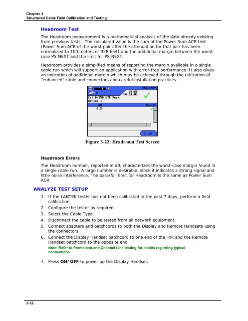
Headroom Test<br />
The Headroom measurement is a mathematical analysis of the data already existing<br />
from previous tests. The calculated value is the sum of the Power Sum ACR test<br />
(Power Sum ACR of the worst pair after the attenuation for that pair has been<br />
normalized to 100 meters or 328 feet) and the additional margin between the worst<br />
case PS NEXT and the limit for PS NEXT.<br />
Headroom provides a simplified means of reporting the margin available in a single<br />
cable run which will support an application with error-free performance. It also gives<br />
an indication of additional margin which may be achieved through the utilization of<br />
“enhanced” cable and connectors and careful installation practices.<br />
Figure 3-22: Headroom Test Screen<br />
Headroom Errors<br />
The Headroom number, reported in dB, characterizes the worst-case margin found in<br />
a single cable run. A large number is desirable, since it indicates a strong signal and<br />
little noise interference. The pass/fail limit for Headroom is the same as Power Sum<br />
ACR.<br />
ANALYZE TEST SETUP<br />
1. If the <strong>LANTEK</strong> tester has not been calibrated in the past 7 days, perform a field<br />
calibration.<br />
2. Configure the tester as required.<br />
3. Select the Cable Type.<br />
4. Disconnect the cable to be tested from all network equipment.<br />
5. Connect adapters and patchcords to both the Display and Remote Handsets using<br />
the connectors.<br />
6. Connect the Display Handset patchcord to one end of the link and the Remote<br />
Handset patchcord to the opposite end.<br />
Note: Refer to Permanent and Channel Link testing for details regarding typical<br />
connections.<br />
7. Press ON/OFF to power up the Display Handset.<br />
3-32


