

LANTEK User Manual - Ideal Industries
LANTEK User Manual - Ideal Industries
LANTEK User Manual - Ideal Industries

You also want an ePaper? Increase the reach of your titles
YUMPU automatically turns print PDFs into web optimized ePapers that Google loves.
Chapter 3<br />
Structured Cable Field Calibration and Testing<br />
Troubleshooting Attenuation Problems<br />
Problem: High Attenuation Reading<br />
Probable Causes<br />
Poor connector termination points.<br />
Excessive cable length.<br />
Incorrect or poor quality adapter cable.<br />
Incorrect cable.<br />
Other Tests Affected Test Possible Result<br />
DC Loop Resistance May be high.<br />
Capacitance<br />
May be high.<br />
Length<br />
May be over limit.<br />
NEXT<br />
May be low on pair combinations.<br />
Average Impedance May be low.<br />
Return Loss<br />
May be over limit.<br />
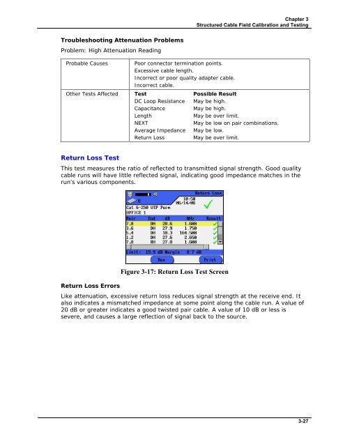
Return Loss Test<br />
This test measures the ratio of reflected to transmitted signal strength. Good quality<br />
cable runs will have little reflected signal, indicating good impedance matches in the<br />
run’s various components.<br />
Return Loss Errors<br />
Figure 3-17: Return Loss Test Screen<br />
Like attenuation, excessive return loss reduces signal strength at the receive end. It<br />
also indicates a mismatched impedance at some point along the cable run. A value of<br />
20 dB or greater indicates a good twisted pair cable. A value of 10 dB or less is<br />
severe, and causes a large reflection of signal back to the source.<br />
3-27


