LANTEK User Manual - Ideal Industries
LANTEK User Manual - Ideal Industries LANTEK User Manual - Ideal Industries
Chapter 3 Structured Cable Field Calibration and Testing NEXT and ELFEXT Errors Crosstalk is usually caused by poor connector termination on the ends of the cable. A low value of dB measurement reading indicates presence of high crosstalk. Troubleshooting NEXT and ELFEXT Problems Problem: Low dB test readings Probable Causes Installed cable or patch cable not correctly rated. Defective, poor quality cable or too many connectors. Poor quality installation at the connection points. Too much insulation has been stripped from the wires at termination. A pair of wires has been untwisted too much at termination. Split-pairs. Poor quality connectors or connectors not rated to desired category. Delay skew (ELFEXT). Excessive noise entering the cabling system from external sources. Other Tests Affected Test Possible Result Return Loss May be over limit. NEXT May show same symptoms. Attenuation Test This test measures the overall signal strength loss in the cable and verifies that it is within acceptable limits. Low attenuation is essential for error-free transmission. Attenuation is measured by injecting a signal of known amplitude at the Remote Handset and reading the amplitude at the Display Handset. Attenuation Errors Figure 3-16: Attenuation Test Screen Attenuation causes a loss of signal strength over a cable. The loss increases with cable length, signal frequency, and temperature. Attenuation testing can be used to find problems in the cable, connectors, or connecting hardware. A high value of dB test reading indicates a high value of attenuation, leading to greater loss of signal. 3-26
Chapter 3 Structured Cable Field Calibration and Testing Troubleshooting Attenuation Problems Problem: High Attenuation Reading Probable Causes Poor connector termination points. Excessive cable length. Incorrect or poor quality adapter cable. Incorrect cable. Other Tests Affected Test Possible Result DC Loop Resistance May be high. Capacitance May be high. Length May be over limit. NEXT May be low on pair combinations. Average Impedance May be low. Return Loss May be over limit. Return Loss Test This test measures the ratio of reflected to transmitted signal strength. Good quality cable runs will have little reflected signal, indicating good impedance matches in the run’s various components. Return Loss Errors Figure 3-17: Return Loss Test Screen Like attenuation, excessive return loss reduces signal strength at the receive end. It also indicates a mismatched impedance at some point along the cable run. A value of 20 dB or greater indicates a good twisted pair cable. A value of 10 dB or less is severe, and causes a large reflection of signal back to the source. 3-27
- Page 18 and 19: Chapter 1 Your Cable Tester HARD AN
- Page 20 and 21: Chapter 1 Your Cable Tester DISPLAY
- Page 22 and 23: Chapter 1 Your Cable Tester OVERVIE
- Page 24 and 25: Chapter 2 Test Setup Procedures AUT
- Page 26 and 27: Chapter 2 Test Setup Procedures TIM
- Page 28 and 29: Chapter 2 Test Setup Procedures Fig
- Page 30 and 31: Chapter 2 Test Setup Procedures PAC
- Page 32 and 33: Chapter 2 Test Setup Procedures TEM
- Page 34 and 35: Chapter 2 Test Setup Procedures Tab
- Page 36 and 37: Chapter 2 Test Setup Procedures Sav
- Page 38 and 39: Chapter 2 Test Setup Procedures OTH
- Page 40 and 41: Chapter 2 Test Setup Procedures Edi
- Page 42 and 43: Chapter 2 Test Setup Procedures ACT
- Page 44 and 45: Chapter 3 Structured Cable Field Ca
- Page 46 and 47: Chapter 3 Structured Cable Field Ca
- Page 48 and 49: Chapter 3 Structured Cable Field Ca
- Page 50 and 51: Chapter 3 Structured Cable Field Ca
- Page 52 and 53: Chapter 3 Structured Cable Field Ca
- Page 54 and 55: Chapter 3 Structured Cable Field Ca
- Page 56 and 57: Chapter 3 Structured Cable Field Ca
- Page 58 and 59: Chapter 3 Structured Cable Field Ca
- Page 60 and 61: Chapter 3 Structured Cable Field Ca
- Page 62 and 63: Chapter 3 Structured Cable Field Ca
- Page 64 and 65: Chapter 3 Structured Cable Field Ca
- Page 66 and 67: Chapter 3 Structured Cable Field Ca
- Page 70 and 71: Chapter 3 Structured Cable Field Ca
- Page 72 and 73: Chapter 3 Structured Cable Field Ca
- Page 74 and 75: Chapter 3 Structured Cable Field Ca
- Page 76 and 77: Chapter 3 Structured Cable Field Ca
- Page 78 and 79: Chapter 3 Structured Cable Field Ca
- Page 80 and 81: Chapter 3 Structured Cable Field Ca
- Page 82 and 83: CHAPTER 4 COAX CABLE FIELD CALIBRAT
- Page 84 and 85: Chapter 4 Coax Cable Field Calibrat
- Page 86 and 87: CHAPTER 5 FIBER OPTICS CABLE FIELD
- Page 88 and 89: Chapter 5 Fiber Optics Cable Field
- Page 90 and 91: Chapter 5 Fiber Optics Cable Field
- Page 92 and 93: Chapter 5 Fiber Optics Cable Field
- Page 94 and 95: Chapter 5 Fiber Optics Cable Field
- Page 96 and 97: Chapter 5 Fiber Optics Cable Field
- Page 98 and 99: Chapter 5 Fiber Optics Cable Field
- Page 100 and 101: Chapter 6 Fiber Optics Diagnostics
- Page 102 and 103: Chapter 6 Fiber Optics Diagnostics
- Page 104 and 105: Chapter 6 Fiber Optics Diagnostics
- Page 106 and 107: Chapter 6 Fiber Optics Diagnostics
- Page 108 and 109: Chapter 6 Fiber Optics Diagnostics
- Page 110 and 111: Chapter 6 Fiber Optics Diagnostics
- Page 112 and 113: CHAPTER 7 LANTEK REPORTER SOFTWARE
- Page 114 and 115: Chapter 7 LANTEK REPORTER Software
- Page 116 and 117: Chapter 7 LANTEK REPORTER Software
Chapter 3<br />
Structured Cable Field Calibration and Testing<br />
NEXT and ELFEXT Errors<br />
Crosstalk is usually caused by poor connector termination on the ends of the cable. A<br />
low value of dB measurement reading indicates presence of high crosstalk.<br />
Troubleshooting NEXT and ELFEXT Problems<br />
Problem: Low dB test readings<br />
Probable Causes<br />
Installed cable or patch cable not correctly rated.<br />
Defective, poor quality cable or too many connectors.<br />
Poor quality installation at the connection points.<br />
Too much insulation has been stripped from the wires at<br />
termination.<br />
A pair of wires has been untwisted too much at termination.<br />
Split-pairs.<br />
Poor quality connectors or connectors not rated to desired<br />
category.<br />
Delay skew (ELFEXT).<br />
Excessive noise entering the cabling system from external sources.<br />
Other Tests Affected Test Possible Result<br />
Return Loss<br />
May be over limit.<br />
NEXT<br />
May show same symptoms.<br />
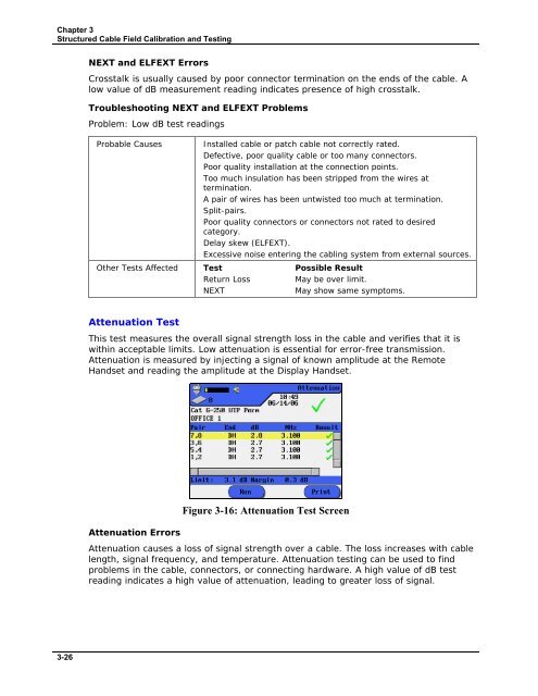
Attenuation Test<br />
This test measures the overall signal strength loss in the cable and verifies that it is<br />
within acceptable limits. Low attenuation is essential for error-free transmission.<br />
Attenuation is measured by injecting a signal of known amplitude at the Remote<br />
Handset and reading the amplitude at the Display Handset.<br />
Attenuation Errors<br />
Figure 3-16: Attenuation Test Screen<br />
Attenuation causes a loss of signal strength over a cable. The loss increases with cable<br />
length, signal frequency, and temperature. Attenuation testing can be used to find<br />
problems in the cable, connectors, or connecting hardware. A high value of dB test<br />
reading indicates a high value of attenuation, leading to greater loss of signal.<br />
3-26


