LANTEK User Manual - Ideal Industries
LANTEK User Manual - Ideal Industries LANTEK User Manual - Ideal Industries
Chapter 3 Structured Cable Field Calibration and Testing Wire Length Test This test measures the length of each wire pair to make sure that the recommended limits for the particular cable type are not exceeded. The Wire Length Test is mainly used for informational purpose only. Depending on the units selected in the Setup menu, length is reported in either feet or meters. Length and NVP Figure 3-11: Wire Length Test Screen Measuring the length of the cable requires that you know the Nominal Velocity of Propagation (NVP) of the cable. Refer to the specification or the manufacturer of the cable you are testing for the cable NVP. If the wire specification is not available, use a known length of good cable (100 - 200 feet) and use the calculate NVP function to enter the total length of the cable and calculate the correct NVP. Wire Length Errors Lengths may differ slightly between pairs in the same cable, due to minor NVP differences between the pairs and physical length differences due to twisting patterns. When electrically measured cable length varies too much from actual length, a problem exists. Troubleshooting Wire Length Problems Problem: Length between a pair of the same cables varies by more than 10%. Probable Causes Incorrect NVP. Excessive cable length. Installed matched terminator not functioning correctly. Cable insulation damage to longer pairs. Break or short in a pair. Elevated capacitance on a pair. Other Tests Affected Test Possible Result DC Loop Resistance May be slightly high or fail. Attenuation May be slightly high or fail. 3-22
Chapter 3 Structured Cable Field Calibration and Testing Resistance Test This test measures the loop resistance of each pair of wires. The test is performed to ensure total loop resistance does not exceed recommended limits. Results are displayed with resistance in ohms for each pair and a comparison limit for the cable type. Resistance Errors Figure 3-12: Resistance Test Screen All four pairs of a network link should have approximately the same resistance. Pair resistance that exceeds the limit is indicated as a failure. The maximum limits in the default tables are based on the maximum length limit of the link or cable segment. Troubleshooting Resistance Problems Problem: Excessive Resistance Probable Causes Mismatched cable types. Poor punch block connection. Poor RJ-45 termination connections. Wire pair has a tap (never done). Cable damage. Shorted cable. Other Tests Affected Test Possible Result Wire Map May fail. Attenuation May fail. NEXT May have false readings. Capacitance May fail. Problem: One wire pair has a very high DC loop resistance, others are normal. Probable Causes Poor connection points. Cable damage. Connector blades not fully piercing wire insulation. Worn Connector Other Tests Affected Test Possible Result Wire Map May fail. Attenuation May fail. NEXT May have false readings. Capacitance May fail. 3-23
- Page 14 and 15: Chapter 1 Your Cable Tester Table 1
- Page 16 and 17: Chapter 1 Your Cable Tester Item DH
- Page 18 and 19: Chapter 1 Your Cable Tester HARD AN
- Page 20 and 21: Chapter 1 Your Cable Tester DISPLAY
- Page 22 and 23: Chapter 1 Your Cable Tester OVERVIE
- Page 24 and 25: Chapter 2 Test Setup Procedures AUT
- Page 26 and 27: Chapter 2 Test Setup Procedures TIM
- Page 28 and 29: Chapter 2 Test Setup Procedures Fig
- Page 30 and 31: Chapter 2 Test Setup Procedures PAC
- Page 32 and 33: Chapter 2 Test Setup Procedures TEM
- Page 34 and 35: Chapter 2 Test Setup Procedures Tab
- Page 36 and 37: Chapter 2 Test Setup Procedures Sav
- Page 38 and 39: Chapter 2 Test Setup Procedures OTH
- Page 40 and 41: Chapter 2 Test Setup Procedures Edi
- Page 42 and 43: Chapter 2 Test Setup Procedures ACT
- Page 44 and 45: Chapter 3 Structured Cable Field Ca
- Page 46 and 47: Chapter 3 Structured Cable Field Ca
- Page 48 and 49: Chapter 3 Structured Cable Field Ca
- Page 50 and 51: Chapter 3 Structured Cable Field Ca
- Page 52 and 53: Chapter 3 Structured Cable Field Ca
- Page 54 and 55: Chapter 3 Structured Cable Field Ca
- Page 56 and 57: Chapter 3 Structured Cable Field Ca
- Page 58 and 59: Chapter 3 Structured Cable Field Ca
- Page 60 and 61: Chapter 3 Structured Cable Field Ca
- Page 62 and 63: Chapter 3 Structured Cable Field Ca
- Page 66 and 67: Chapter 3 Structured Cable Field Ca
- Page 68 and 69: Chapter 3 Structured Cable Field Ca
- Page 70 and 71: Chapter 3 Structured Cable Field Ca
- Page 72 and 73: Chapter 3 Structured Cable Field Ca
- Page 74 and 75: Chapter 3 Structured Cable Field Ca
- Page 76 and 77: Chapter 3 Structured Cable Field Ca
- Page 78 and 79: Chapter 3 Structured Cable Field Ca
- Page 80 and 81: Chapter 3 Structured Cable Field Ca
- Page 82 and 83: CHAPTER 4 COAX CABLE FIELD CALIBRAT
- Page 84 and 85: Chapter 4 Coax Cable Field Calibrat
- Page 86 and 87: CHAPTER 5 FIBER OPTICS CABLE FIELD
- Page 88 and 89: Chapter 5 Fiber Optics Cable Field
- Page 90 and 91: Chapter 5 Fiber Optics Cable Field
- Page 92 and 93: Chapter 5 Fiber Optics Cable Field
- Page 94 and 95: Chapter 5 Fiber Optics Cable Field
- Page 96 and 97: Chapter 5 Fiber Optics Cable Field
- Page 98 and 99: Chapter 5 Fiber Optics Cable Field
- Page 100 and 101: Chapter 6 Fiber Optics Diagnostics
- Page 102 and 103: Chapter 6 Fiber Optics Diagnostics
- Page 104 and 105: Chapter 6 Fiber Optics Diagnostics
- Page 106 and 107: Chapter 6 Fiber Optics Diagnostics
- Page 108 and 109: Chapter 6 Fiber Optics Diagnostics
- Page 110 and 111: Chapter 6 Fiber Optics Diagnostics
- Page 112 and 113: CHAPTER 7 LANTEK REPORTER SOFTWARE
Chapter 3<br />
Structured Cable Field Calibration and Testing<br />
Resistance Test<br />
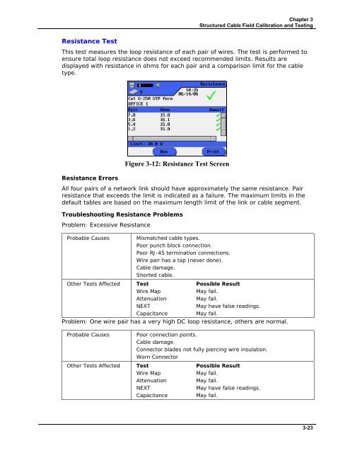
This test measures the loop resistance of each pair of wires. The test is performed to<br />
ensure total loop resistance does not exceed recommended limits. Results are<br />
displayed with resistance in ohms for each pair and a comparison limit for the cable<br />
type.<br />
Resistance Errors<br />
Figure 3-12: Resistance Test Screen<br />
All four pairs of a network link should have approximately the same resistance. Pair<br />
resistance that exceeds the limit is indicated as a failure. The maximum limits in the<br />
default tables are based on the maximum length limit of the link or cable segment.<br />
Troubleshooting Resistance Problems<br />
Problem: Excessive Resistance<br />
Probable Causes<br />
Mismatched cable types.<br />
Poor punch block connection.<br />
Poor RJ-45 termination connections.<br />
Wire pair has a tap (never done).<br />
Cable damage.<br />
Shorted cable.<br />
Other Tests Affected Test Possible Result<br />
Wire Map<br />
May fail.<br />
Attenuation<br />
May fail.<br />
NEXT<br />
May have false readings.<br />
Capacitance<br />
May fail.<br />
Problem: One wire pair has a very high DC loop resistance, others are normal.<br />
Probable Causes<br />
Poor connection points.<br />
Cable damage.<br />
Connector blades not fully piercing wire insulation.<br />
Worn Connector<br />
Other Tests Affected Test Possible Result<br />
Wire Map<br />
May fail.<br />
Attenuation<br />
May fail.<br />
NEXT<br />
May have false readings.<br />
Capacitance<br />
May fail.<br />
3-23


