LANTEK User Manual - Ideal Industries
LANTEK User Manual - Ideal Industries LANTEK User Manual - Ideal Industries
Chapter 6 Fiber Optics Diagnostics (TRACETEK) TROUBLESHOOTING WITH TRACETEK TRACETEK can be an invaluable tool for troubleshooting a variety of network problems. One application is to locate a break in a cable. In a new installation, TRACETEK can be used with a power meter/light source test kit such as FIBERTEK to characterize a link and map the distance to known events. In this example we’re testing a backbone link consisting of 44 m of cross-connect cable to a 717 m backbone, followed by another 40 m of cross-connect. Figure A is the FIBERTEK (power meter/light source) result from the link indicating a passing result. In Figure B, we see the connectors at 40 m and 760 m, as well as the end of the fiber at 801m. The connectors at 40 m and 760 m appear to be in good condition with a reflection that is just below half scale. Figure A Figure B Figures C and D show the same link failing. The FIBERTEK screen tells the degree of link failure but it does not help isolate the problem. TRACETEK screen (Figure D) shows the connector at 761 m is nearly full scale, an indication that it has become dirty or damaged. Figure C Figure D In this situation, the best course of action is to clean the connection at 760 m and check it with a microscope (IDEAL P/N 45-332) before re-testing. Consult the instructions included with the IDEAL Starter Cleaning Kit for the best methods to clean connectors and couplers. 6-10
Chapter 6 Fiber Optics Diagnostics (TRACETEK) Q&A: IDENTIFYING TRACETEK CONFIGURATION PROBLEMS Q1: Why is it so important that my launch cable connectors be kept clean? A1: Unlike a traditional light source, the most high-powered of which have output levels significantly less than 1mW, TRACETEK’s high-power laser source launches up to 40 mW of power. When dealing with return loss measurements, more power out means more power back. With the levels that TRACETEK operates at, a dirty launch cable will immediately reflect a large amount of power back at the detector, essentially causing temporary blindness of the detector. Keep your connectors clean! Q2: What will happen if I set the Resolution incorrectly? A2: Incorrectly setting the Resolution of TRACETEK will not cause any damage to the tester or cable. It will usually result in a garbled display that is a result of too much power being injected into a short cable, leading to very high reflections since the cable itself cannot attenuate the return pulse. Or, in the case of a very long cable, there will not be enough power for TRACETEK to see the end, meaning it will be unable to properly scale the screen. Here are a few images that result when the Resolution setting is not optimally set for the fiber being tested (Figures E-H). ‣ In this example a 1000 m cable was tested with the Resolution set to MED. The result is that the ramp time, which adjusts the scaling, is too short. The recommended maximum distance for MED mode is 850 m. Change to LOW Resolution and try again Figure E ‣ With the Resolution now set to LOW, the end of the 1000 m fiber is clearly visible. Figure F 6-11
- Page 58 and 59: Chapter 3 Structured Cable Field Ca
- Page 60 and 61: Chapter 3 Structured Cable Field Ca
- Page 62 and 63: Chapter 3 Structured Cable Field Ca
- Page 64 and 65: Chapter 3 Structured Cable Field Ca
- Page 66 and 67: Chapter 3 Structured Cable Field Ca
- Page 68 and 69: Chapter 3 Structured Cable Field Ca
- Page 70 and 71: Chapter 3 Structured Cable Field Ca
- Page 72 and 73: Chapter 3 Structured Cable Field Ca
- Page 74 and 75: Chapter 3 Structured Cable Field Ca
- Page 76 and 77: Chapter 3 Structured Cable Field Ca
- Page 78 and 79: Chapter 3 Structured Cable Field Ca
- Page 80 and 81: Chapter 3 Structured Cable Field Ca
- Page 82 and 83: CHAPTER 4 COAX CABLE FIELD CALIBRAT
- Page 84 and 85: Chapter 4 Coax Cable Field Calibrat
- Page 86 and 87: CHAPTER 5 FIBER OPTICS CABLE FIELD
- Page 88 and 89: Chapter 5 Fiber Optics Cable Field
- Page 90 and 91: Chapter 5 Fiber Optics Cable Field
- Page 92 and 93: Chapter 5 Fiber Optics Cable Field
- Page 94 and 95: Chapter 5 Fiber Optics Cable Field
- Page 96 and 97: Chapter 5 Fiber Optics Cable Field
- Page 98 and 99: Chapter 5 Fiber Optics Cable Field
- Page 100 and 101: Chapter 6 Fiber Optics Diagnostics
- Page 102 and 103: Chapter 6 Fiber Optics Diagnostics
- Page 104 and 105: Chapter 6 Fiber Optics Diagnostics
- Page 106 and 107: Chapter 6 Fiber Optics Diagnostics
- Page 110 and 111: Chapter 6 Fiber Optics Diagnostics
- Page 112 and 113: CHAPTER 7 LANTEK REPORTER SOFTWARE
- Page 114 and 115: Chapter 7 LANTEK REPORTER Software
- Page 116 and 117: Chapter 7 LANTEK REPORTER Software
- Page 118 and 119: Chapter 7 LANTEK REPORTER Software
- Page 120 and 121: Chapter 7 LANTEK REPORTER Software
- Page 122 and 123: Chapter 7 LANTEK REPORTER Software
- Page 124 and 125: Chapter 7 LANTEK REPORTER Software
- Page 126 and 127: Chapter 7 LANTEK REPORTER Software
- Page 128 and 129: Chapter 7 LANTEK REPORTER Software
- Page 130 and 131: Chapter 7 LANTEK REPORTER Software
- Page 132 and 133: Chapter 7 LANTEK REPORTER Software
- Page 134 and 135: Chapter 7 LANTEK REPORTER Software
- Page 136 and 137: Chapter 7 LANTEK REPORTER Software
- Page 138 and 139: Chapter 7 LANTEK REPORTER Software
- Page 140 and 141: APPENDIX A SAFETY PRECAUTIONS HANDL
- Page 142 and 143: APPENDIX B CUSTOMER SUPPORT CUSTOME
- Page 144 and 145: Appendix B Customer Support IDEAL I
- Page 146 and 147: Appendix C Fiber Optic Cabling Stan
Chapter 6<br />
Fiber Optics Diagnostics (TRACETEK)<br />
Q&A: IDENTIFYING TRACETEK CONFIGURATION PROBLEMS<br />
Q1: Why is it so important that my launch cable connectors be kept clean?<br />
A1: Unlike a traditional light source, the most high-powered of which have output<br />
levels significantly less than 1mW, TRACETEK’s high-power laser source launches up<br />
to 40 mW of power. When dealing with return loss measurements, more power out<br />
means more power back. With the levels that TRACETEK operates at, a dirty launch<br />
cable will immediately reflect a large amount of power back at the detector, essentially<br />
causing temporary blindness of the detector. Keep your connectors clean!<br />
Q2: What will happen if I set the Resolution incorrectly?<br />
A2: Incorrectly setting the Resolution of TRACETEK will not cause any damage to the<br />
tester or cable. It will usually result in a garbled display that is a result of too much<br />
power being injected into a short cable, leading to very high reflections since the cable<br />
itself cannot attenuate the return pulse. Or, in the case of a very long cable, there will<br />
not be enough power for TRACETEK to see the end, meaning it will be unable to<br />
properly scale the screen. Here are a few images that result when the Resolution<br />
setting is not optimally set for the fiber being tested (Figures E-H).<br />
‣ In this example a 1000 m cable was tested with the Resolution set to MED. The<br />
result is that the ramp time, which adjusts the scaling, is too short. The<br />
recommended maximum distance for MED mode is 850 m. Change to LOW<br />
Resolution and try again<br />
Figure E<br />
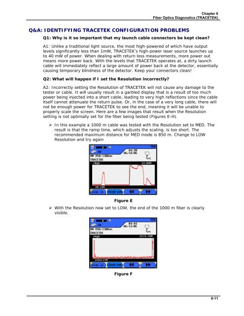
‣ With the Resolution now set to LOW, the end of the 1000 m fiber is clearly<br />
visible.<br />
Figure F<br />
6-11


