LANTEK User Manual - Ideal Industries
LANTEK User Manual - Ideal Industries LANTEK User Manual - Ideal Industries
Chapter 6 Fiber Optics Diagnostics (TRACETEK) After cleaning the two center connectors, shown in the figure above, it is apparent there is some improvement in return loss. However, in this case we expect the Fresnel to be larger than before because of the higher launch power TRACETEK uses in the Medium Resolution mode. Also notice that the Fresnels are wider than before. This width is known as the dead zone, which is the distance that the receiver is blinded by the reflection of each event. High output power and dirty or poorly polished connectors will lead to an increased dead zone. In its High Resolution mode with clean connectors, TRACETEK will have a dead zone of 2 m, while in the Medium and Low Resolution Modes the dead-zones will be about 8 m. When testing through patch panels or other cross-connect devices best results will be achieved with the High-Resolution mode. Refer to Table 1 when deciding which of the three resolution modes is best for your application. TESTING WITH TRACETEK The TRACETEK system is simple to use and requires no warm-up time. 1. Insert the TRACETEK adapter into the LANTEK Cable Certifier. 2. Clean the launch cable and attach it to the adapter. 3. Using a Good Quality mating adapter, attach the launch cable to the fiber to be tested. Clean all connections. Make sure the launch cable connector is aligned with the TRACETEK connector slot to assure proper mating of the connector. Figure 6-4: LANTEK/TRACETEK Configuration on a Fiber 4. Select Fiber Optics on the Display Handset Ready screen. The Fiber Cable Type screen appears. 5. Highlight the desired fiber type and press ENTER to accept the new fiber type. 6. From the Ready screen of the LANTEK main unit, Press AUTOTEST or select Analyze to open the Analyze menu screen. 7. The Analyze menu provides three resolution options: High, Medium, and Low. The default resolution is High. 6-8
Chapter 6 Fiber Optics Diagnostics (TRACETEK) Figure 6-5: TRACETEK Analyze Menu Screen 8. Highlight the desired resolution and press ENTER. The LANTEK Cable Certifiers will conduct the measurement. 9. When the test is complete, the results are displayed on screen, left to right, with the last event usually taking place at the end of the fiber. Note: Sometimes the end of the fiber (EOF) is not where it is expected due to poor splices or cuts. EOF is the point where TRACETEK detects a large reflection (about -14dB) which can be the actual EOF, a bad connector, or a break in the fiber. Figure 6-6: TRACETEK Test Results Screen Using the high resolution setting is best for cables under 800 m (2625 ft) in length. The distance to the end of the fiber is displayed on the screen in the lower left-hand corner of the display. The vertical cursor can be used to find the distance to an event by moving it along the trace where the event is indicated. The distance to this point appears on the screen in the upper right-hand corner of the display. SAVING TRACETEK RESULTS Like other tests, the resultant plot from TRACETEK can be stored in the LANTEK handset and recalled or uploaded to a PC using the LANTEK Reporter software. 1. From the TRACETEK display, press SHIFT and the key. 2. Enter a test record name and press ENTER to save the record. 6-9
- Page 56 and 57: Chapter 3 Structured Cable Field Ca
- Page 58 and 59: Chapter 3 Structured Cable Field Ca
- Page 60 and 61: Chapter 3 Structured Cable Field Ca
- Page 62 and 63: Chapter 3 Structured Cable Field Ca
- Page 64 and 65: Chapter 3 Structured Cable Field Ca
- Page 66 and 67: Chapter 3 Structured Cable Field Ca
- Page 68 and 69: Chapter 3 Structured Cable Field Ca
- Page 70 and 71: Chapter 3 Structured Cable Field Ca
- Page 72 and 73: Chapter 3 Structured Cable Field Ca
- Page 74 and 75: Chapter 3 Structured Cable Field Ca
- Page 76 and 77: Chapter 3 Structured Cable Field Ca
- Page 78 and 79: Chapter 3 Structured Cable Field Ca
- Page 80 and 81: Chapter 3 Structured Cable Field Ca
- Page 82 and 83: CHAPTER 4 COAX CABLE FIELD CALIBRAT
- Page 84 and 85: Chapter 4 Coax Cable Field Calibrat
- Page 86 and 87: CHAPTER 5 FIBER OPTICS CABLE FIELD
- Page 88 and 89: Chapter 5 Fiber Optics Cable Field
- Page 90 and 91: Chapter 5 Fiber Optics Cable Field
- Page 92 and 93: Chapter 5 Fiber Optics Cable Field
- Page 94 and 95: Chapter 5 Fiber Optics Cable Field
- Page 96 and 97: Chapter 5 Fiber Optics Cable Field
- Page 98 and 99: Chapter 5 Fiber Optics Cable Field
- Page 100 and 101: Chapter 6 Fiber Optics Diagnostics
- Page 102 and 103: Chapter 6 Fiber Optics Diagnostics
- Page 104 and 105: Chapter 6 Fiber Optics Diagnostics
- Page 108 and 109: Chapter 6 Fiber Optics Diagnostics
- Page 110 and 111: Chapter 6 Fiber Optics Diagnostics
- Page 112 and 113: CHAPTER 7 LANTEK REPORTER SOFTWARE
- Page 114 and 115: Chapter 7 LANTEK REPORTER Software
- Page 116 and 117: Chapter 7 LANTEK REPORTER Software
- Page 118 and 119: Chapter 7 LANTEK REPORTER Software
- Page 120 and 121: Chapter 7 LANTEK REPORTER Software
- Page 122 and 123: Chapter 7 LANTEK REPORTER Software
- Page 124 and 125: Chapter 7 LANTEK REPORTER Software
- Page 126 and 127: Chapter 7 LANTEK REPORTER Software
- Page 128 and 129: Chapter 7 LANTEK REPORTER Software
- Page 130 and 131: Chapter 7 LANTEK REPORTER Software
- Page 132 and 133: Chapter 7 LANTEK REPORTER Software
- Page 134 and 135: Chapter 7 LANTEK REPORTER Software
- Page 136 and 137: Chapter 7 LANTEK REPORTER Software
- Page 138 and 139: Chapter 7 LANTEK REPORTER Software
- Page 140 and 141: APPENDIX A SAFETY PRECAUTIONS HANDL
- Page 142 and 143: APPENDIX B CUSTOMER SUPPORT CUSTOME
- Page 144 and 145: Appendix B Customer Support IDEAL I
- Page 146 and 147: Appendix C Fiber Optic Cabling Stan
Chapter 6<br />
Fiber Optics Diagnostics (TRACETEK)<br />
After cleaning the two center connectors, shown in the figure above, it is apparent<br />
there is some improvement in return loss. However, in this case we expect the Fresnel<br />
to be larger than before because of the higher launch power TRACETEK uses in the<br />
Medium Resolution mode. Also notice that the Fresnels are wider than before. This<br />
width is known as the dead zone, which is the distance that the receiver is blinded by<br />
the reflection of each event. High output power and dirty or poorly polished<br />
connectors will lead to an increased dead zone.<br />
In its High Resolution mode with clean connectors, TRACETEK will have a dead zone of<br />
2 m, while in the Medium and Low Resolution Modes the dead-zones will be about 8<br />
m. When testing through patch panels or other cross-connect devices best results will<br />
be achieved with the High-Resolution mode. Refer to Table 1 when deciding which of<br />
the three resolution modes is best for your application.<br />
TESTING WITH TRACETEK<br />
The TRACETEK system is simple to use and requires no warm-up time.<br />
1. Insert the TRACETEK adapter into the <strong>LANTEK</strong> Cable Certifier.<br />
2. Clean the launch cable and attach it to the adapter.<br />
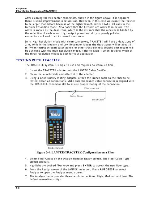
3. Using a Good Quality mating adapter, attach the launch cable to the fiber to be<br />
tested. Clean all connections. Make sure the launch cable connector is aligned with<br />
the TRACETEK connector slot to assure proper mating of the connector.<br />
Figure 6-4: <strong>LANTEK</strong>/TRACETEK Configuration on a Fiber<br />
4. Select Fiber Optics on the Display Handset Ready screen. The Fiber Cable Type<br />
screen appears.<br />
5. Highlight the desired fiber type and press ENTER to accept the new fiber type.<br />
6. From the Ready screen of the <strong>LANTEK</strong> main unit, Press AUTOTEST or select<br />
Analyze to open the Analyze menu screen.<br />
7. The Analyze menu provides three resolution options: High, Medium, and Low. The<br />
default resolution is High.<br />
6-8


