

LANTEK User Manual - Ideal Industries
LANTEK User Manual - Ideal Industries
LANTEK User Manual - Ideal Industries

Create successful ePaper yourself
Turn your PDF publications into a flip-book with our unique Google optimized e-Paper software.
Chapter 6<br />
Fiber Optics Diagnostics (TRACETEK)<br />
TRACETEK displays its measurement data in a graphical format similar to that of an<br />
ODTR, with the X-axis representing the distance from the handset and the Y-axis<br />
displaying the relative reflection (Return Loss) of each event. TRACETEK instantly<br />
displays the overall length to the end of the fiber and allows the operator to scroll a<br />
cursor to find the distance to any event on the screen. This functionality allows the<br />
operator to quickly measure overall fiber length, locate breaks in the fiber, locate<br />
individual reflective events, and check the relative reflection of events to identify<br />
defective connections.<br />
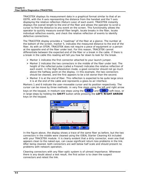
The TRACETEK display provides a “roadmap” of the fiber at a glance. The number at<br />
the bottom of the screen, marker 5, indicates the measured distance to the end of the<br />
fiber. As with an OTDR, TRACETEK does not require a piece of equipment or a person<br />
at the opposite end of the fiber under test. For this reason, TRACETEK cannot<br />
differentiate between the expected end of the fiber or a break in the cable. If there is<br />
a break in the cable this reading will tell you how far down to look for the break.<br />
‣ Marker 1 indicates the first connector attached to your launch jumper.<br />
‣ Marker 2 indicates the two connectors in the middle of the fiber under test. The<br />
height of the reflected pulse (called a Fresnel) indicates the relative reflection of<br />
each event. In the High-Resolution mode, a good connector should not go much<br />
above the halfway point on the display. In this example, the two connectors<br />
should be cleaned, and the first appears to be a bit worse than the second.<br />
‣ Marker 3 is at the end of fiber. This reflection is expected to be quite large since<br />
it is at the end of the cable and represents a glass-to-air interface.<br />
Markers 1 and 6 indicate the user-moveable cursor and its position respectively. The<br />
cursor can be move by three methods: in very fine steps using the left and right arrow<br />
keys on the keypad, in medium size steps using the and soft-keys, or<br />
in large steps by holding the SHIFT button while pressing the LEFT/RIGHT ARROW<br />
keys on the keypad.<br />
In the figure above, the display shows a trace of the same fiber as before, but the two<br />
connectors in the middle were cleaned using the IDEAL Starter Cleaning Kit included<br />
with your TRACETEK module. It is clearly evident that a dirty connector, even one that<br />
appears clean to the naked eye, can cause significant return loss problems in the link.<br />
After being cleaned, both connectors are well below half scale and should present no<br />
problems with network operation.<br />
Cleaning connectors with any fiber-optic system is of utmost importance. Whenever<br />
there is any doubt about a test result, the first action is to clean the suspect<br />
connectors and retest the link.<br />
6-6


