LANTEK User Manual - Ideal Industries
LANTEK User Manual - Ideal Industries LANTEK User Manual - Ideal Industries
Chapter 6 Fiber Optics Diagnostics (TRACETEK) Resolution Setting Table 6-1: Resolution Settings and Recommendations Power Distance Scale Distance Recommendation High Low Short 0-800 m (0-2625 ft) Med High Short 250-850 m (820-2790 ft) Low High Long 500-4000 m (1640-13120 ft) Note: The recommendations for distance do not reflect the absolute minimum or maximum distance capabilities of TRACETEK. These are recommendations that will yield the best results in most cases. You should feel free to experiment and determine the setting that gives the best result for a particular test configuration. HIGH RESOLUTION High Resolution provides accurate back reflection measurement of fiber and will resolve individual events as close as 2 meters apart at rated accuracy. This setting is used to check for connector quality, optimized for short-distance cables with lengths of no more than 800 meters and mostly used on horizontal links and shorter backbone cables. This mode has a “low power” setting. MEDIUM (MED) RESOLUTION Medium Resolution provides accurate back reflection measurement of lengths and will resolve measure events 8 meters and up at distances of 850 meters. This setting is primarily used to locate high quality connections for documentation purposes. It is on cables between 250-850 m in length or when trying to locate low-reflection events such as mechanical splices or connectors where the polish is so good that they do not reflect enough light in the low power mode to be detected. This mode has a “long laser pulse” setting. LOW RESOLUTION Low Resolution provides accurate back reflection measurements for cables between 500 and 4000 meters in length, since most connectors and mechanical splices will be visible in this mode. This mode combines the “high power/long pulse” of the Medium Resolution mode with long-distance scaling. TRACETEK OVERVIEW High-bandwidth optical networks have become increasingly sensitive to signal transmission problems. In many cases the channel insertion loss is the only parameter that is measured to make a determination that a link’s performance is satisfactory. Channel insertion loss only measures the weakening of the signal from one end of a fiber optic link to the other, making sure that enough optical power is present at the receiver to ensure the optical transceivers can “see” each other. FIBERTEK is an exceptional tool to certify proper link channel loss. However, in a situation when a certification test fails or there are unusual network performance problems, another tool can help isolate cabling problems. TRACETEK is a unique tool that provides many of the useful features of an OTDR without the high cost or complex parameters to set up. An easy to use diagnostic tool, TRACETEK allows the user to measure the total length of a link, measure the distance to a reflective event such as a connector, and most importantly, identify faulty connections. 6-4
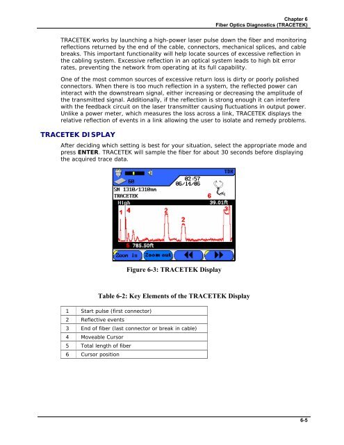
Chapter 6 Fiber Optics Diagnostics (TRACETEK) TRACETEK works by launching a high-power laser pulse down the fiber and monitoring reflections returned by the end of the cable, connectors, mechanical splices, and cable breaks. This important functionality will help locate sources of excessive reflection in the cabling system. Excessive reflection in an optical system leads to high bit error rates, preventing the network from operating at its full capability. One of the most common sources of excessive return loss is dirty or poorly polished connectors. When there is too much reflection in a system, the reflected power can interact with the downstream signal, either increasing or decreasing the amplitude of the transmitted signal. Additionally, if the reflection is strong enough it can interfere with the feedback circuit on the laser transmitter causing fluctuations in output power. Unlike a power meter, which measures the loss across a link, TRACETEK displays the relative reflection of events in a link allowing the user to isolate and remedy problems. TRACETEK DISPLAY After deciding which setting is best for your situation, select the appropriate mode and press ENTER. TRACETEK will sample the fiber for about 30 seconds before displaying the acquired trace data. Figure 6-3: TRACETEK Display Table 6-2: Key Elements of the TRACETEK Display 1 Start pulse (first connector) 2 Reflective events 3 End of fiber (last connector or break in cable) 4 Moveable Cursor 5 Total length of fiber 6 Cursor position 6-5
- Page 52 and 53: Chapter 3 Structured Cable Field Ca
- Page 54 and 55: Chapter 3 Structured Cable Field Ca
- Page 56 and 57: Chapter 3 Structured Cable Field Ca
- Page 58 and 59: Chapter 3 Structured Cable Field Ca
- Page 60 and 61: Chapter 3 Structured Cable Field Ca
- Page 62 and 63: Chapter 3 Structured Cable Field Ca
- Page 64 and 65: Chapter 3 Structured Cable Field Ca
- Page 66 and 67: Chapter 3 Structured Cable Field Ca
- Page 68 and 69: Chapter 3 Structured Cable Field Ca
- Page 70 and 71: Chapter 3 Structured Cable Field Ca
- Page 72 and 73: Chapter 3 Structured Cable Field Ca
- Page 74 and 75: Chapter 3 Structured Cable Field Ca
- Page 76 and 77: Chapter 3 Structured Cable Field Ca
- Page 78 and 79: Chapter 3 Structured Cable Field Ca
- Page 80 and 81: Chapter 3 Structured Cable Field Ca
- Page 82 and 83: CHAPTER 4 COAX CABLE FIELD CALIBRAT
- Page 84 and 85: Chapter 4 Coax Cable Field Calibrat
- Page 86 and 87: CHAPTER 5 FIBER OPTICS CABLE FIELD
- Page 88 and 89: Chapter 5 Fiber Optics Cable Field
- Page 90 and 91: Chapter 5 Fiber Optics Cable Field
- Page 92 and 93: Chapter 5 Fiber Optics Cable Field
- Page 94 and 95: Chapter 5 Fiber Optics Cable Field
- Page 96 and 97: Chapter 5 Fiber Optics Cable Field
- Page 98 and 99: Chapter 5 Fiber Optics Cable Field
- Page 100 and 101: Chapter 6 Fiber Optics Diagnostics
- Page 104 and 105: Chapter 6 Fiber Optics Diagnostics
- Page 106 and 107: Chapter 6 Fiber Optics Diagnostics
- Page 108 and 109: Chapter 6 Fiber Optics Diagnostics
- Page 110 and 111: Chapter 6 Fiber Optics Diagnostics
- Page 112 and 113: CHAPTER 7 LANTEK REPORTER SOFTWARE
- Page 114 and 115: Chapter 7 LANTEK REPORTER Software
- Page 116 and 117: Chapter 7 LANTEK REPORTER Software
- Page 118 and 119: Chapter 7 LANTEK REPORTER Software
- Page 120 and 121: Chapter 7 LANTEK REPORTER Software
- Page 122 and 123: Chapter 7 LANTEK REPORTER Software
- Page 124 and 125: Chapter 7 LANTEK REPORTER Software
- Page 126 and 127: Chapter 7 LANTEK REPORTER Software
- Page 128 and 129: Chapter 7 LANTEK REPORTER Software
- Page 130 and 131: Chapter 7 LANTEK REPORTER Software
- Page 132 and 133: Chapter 7 LANTEK REPORTER Software
- Page 134 and 135: Chapter 7 LANTEK REPORTER Software
- Page 136 and 137: Chapter 7 LANTEK REPORTER Software
- Page 138 and 139: Chapter 7 LANTEK REPORTER Software
- Page 140 and 141: APPENDIX A SAFETY PRECAUTIONS HANDL
- Page 142 and 143: APPENDIX B CUSTOMER SUPPORT CUSTOME
- Page 144 and 145: Appendix B Customer Support IDEAL I
- Page 146 and 147: Appendix C Fiber Optic Cabling Stan
Chapter 6<br />
Fiber Optics Diagnostics (TRACETEK)<br />
TRACETEK works by launching a high-power laser pulse down the fiber and monitoring<br />
reflections returned by the end of the cable, connectors, mechanical splices, and cable<br />
breaks. This important functionality will help locate sources of excessive reflection in<br />
the cabling system. Excessive reflection in an optical system leads to high bit error<br />
rates, preventing the network from operating at its full capability.<br />
One of the most common sources of excessive return loss is dirty or poorly polished<br />
connectors. When there is too much reflection in a system, the reflected power can<br />
interact with the downstream signal, either increasing or decreasing the amplitude of<br />
the transmitted signal. Additionally, if the reflection is strong enough it can interfere<br />
with the feedback circuit on the laser transmitter causing fluctuations in output power.<br />
Unlike a power meter, which measures the loss across a link, TRACETEK displays the<br />
relative reflection of events in a link allowing the user to isolate and remedy problems.<br />
TRACETEK DISPLAY<br />
After deciding which setting is best for your situation, select the appropriate mode and<br />
press ENTER. TRACETEK will sample the fiber for about 30 seconds before displaying<br />
the acquired trace data.<br />
Figure 6-3: TRACETEK Display<br />
Table 6-2: Key Elements of the TRACETEK Display<br />
1 Start pulse (first connector)<br />
2 Reflective events<br />
3 End of fiber (last connector or break in cable)<br />
4 Moveable Cursor<br />
5 Total length of fiber<br />
6 Cursor position<br />
6-5


