10 pluggable screw terminals - BMR Gmbh
10 pluggable screw terminals - BMR Gmbh
10 pluggable screw terminals - BMR Gmbh

Create successful ePaper yourself
Turn your PDF publications into a flip-book with our unique Google optimized e-Paper software.
<strong>BMR</strong> GmbH 2009<br />
MANUAL<br />
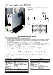
Picture shows version SSE, for further available models, see point 3, page 8.
SFU 0303<br />
2<br />
Congratulation<br />
for purchasing a <strong>BMR</strong>-GmbH product.<br />
We thank you for the decision for<br />
choosing a <strong>BMR</strong>-GmbH device<br />
and wish you much success.<br />
Please read<br />
this manual carefully<br />
before the first use<br />
Version 18.Feb.2009
Contents:<br />
1. Introduction 4<br />
2. Description and Features 6<br />
3. Specifications of Device 8<br />
4. Block Diagram 9<br />
5. Technical Data <strong>10</strong><br />
6. Safety and Caution Instructions 11<br />
7. View of Front Panel 12<br />
8. Connections, Plugs and Pin Assignments 13<br />
8.1 Digital and Analog Inputs X2 14<br />
8.2 Digital and Analog Outputs X3 15<br />
8.3 Spindle Interface X416<br />
8.4 Mains Connection, Spindle Connection with Plug Connectors 17<br />
8.5 View of Strip Terminal 17<br />
8.6 RS232, RS485 18<br />
8.7 USB Connection 18<br />
9. Description of Function, Setup, Operation 19<br />
9.1 Starting the Converter 20<br />
9.2 Status Information of LED Display 21<br />
9.3 LCD Operating Panel 22<br />
9.4 Adjustment of Rotation Speed 25<br />
9.5 Safety Functions 26<br />
9.6 Safe Pulse Inhibitor according to EN 954-1 K3 27<br />
<strong>10</strong>. Profibus Connection 27<br />
11. Parametrisation, Configuration with Windows Software 28<br />
12. Automatic Calibration of Spindles and Adjustment 29<br />
13. Examples of Connections 31<br />
13.1 Logic and Safety Circuit 31<br />
13.2 Mains and Spindle Connection 32<br />
14. EMC 33<br />
15. Troubleshooting 34<br />
16. Mechanics, Views, Dimensions 37<br />
17. EC Declaration of Conformity 38<br />
18. General Hints 39<br />
19. Warranty 40<br />
20. Accessories 41<br />
3
SFU 0303<br />
1. Introduction<br />
Due to its construction, the rotation speed of a 3-phase AC motor is directly dependent on<br />
the frequency of the connected network and on the number of poles. In the case of a network<br />
frequency of 50 Hz and a 2-pole motor, the nominal rotation speed is 50 r/s * 60 = 3000 rpm.<br />
In the case of DC motors (brushless DC), the rotation speed is dependent on the voltage<br />
applied.<br />
AC-Spindles offer a variety of advantages in the industrial area, such as brushless operation,<br />
no wear and tear, favourable capacity/weight ratio, high rotation speed, and much more.<br />
Accordingly, they can be used in a variety of areas, such as in milling and grinding spindles<br />
or in drilling machines.<br />
The advantages of SFU0303 compared to similar frequency converters:<br />
4<br />
Safe pulse inhibitor, authorized according to current regulations of EN 954-1 category 3<br />
In an industrial network an output of up to 5kVA<br />
High efficiency because of symmetrical PWM<br />
Real time vector control for operation without sensor<br />
Maximal torque even with a very low rotation speed<br />
Highest acceleration times can be achieved for low process times, e.g. 25.000 rpm/sec for<br />
a 2.2 KW motor (e.g. for robot applications in process technology)<br />
PAM control possible through regulated intermediate circuit (optional)<br />
Very low rotation speed (<strong>10</strong> rpm) possible e.g. for the start of tool change positions<br />
Lowest possible power input through real time power control system<br />
Optimal integration into existent programmable controllers through open I/0 configuration<br />
Interface to profibus, RS485, RS232, USB<br />
Datalogger (optional) integrated through PC software. Recording of any length of all<br />
relevant parameters in the converter possible. Ideal for the setup of the processing step
Autotuning function -Automatic learning of the motor’s characteristic curves<br />
Test run with graphical evaluation of the motor currents/voltages<br />
Up to 16 different characteristics of spindles can be stored<br />
Very user-friendly debugging interface for setup control<br />
Start/stop interface for cyclic permanent tests or remote control<br />
Operating panel detachable and with extension cable to be used as remote control<br />
Planned for the industrial use when drilling, grinding, milling. Swarf-proof housing<br />
construction prevents the intrusion of impurity into the control electronics<br />
Very compact form of housing allows the unproblematic installation into the<br />
control cabinet<br />
19” housing version for 3HE standard racks<br />
Custom housings on request<br />
User-friendly plug-in system for power and control connections<br />
Wide range of mains voltage 115 V – 230 V<br />
Plug connectors with <strong>screw</strong> elements<br />
Automatic decelaration of the spindle after emergency stop or mains failure<br />
Illuminated amber plain text display<br />
Rotary encoder without mechanical catch for rotation speed control and menu control<br />
Very user friendly operating menu in plain text<br />
Temperature controlled fan<br />
Different models<br />
USB connection<br />
Fully functional even without operating panel<br />
Direct RS232 connection with adapter cable<br />
5
SFU 0303<br />
2. Description and Features<br />
Operation of AC and DC motors<br />
The high frequency converter SFU-0303 allows for rotation frequencies in AC motors of up<br />
to 500,000 rpm in a 2-pole motor and in DC motors of up to 60,000 rpm.<br />
High output power (3.6 kV with 230 V / 2 kVA with 115 V) in a compact design.<br />
The core of SFU-0303 is a digital signal processor (DSP) which produces all output parameters<br />
and collects signals.<br />
All parameters like power, voltage and frequency are collected in real time and are regulated<br />
by the implemented vector control depending on the load.<br />
High-precision sinusoidal output signals with a low distortion factor and low deformation<br />
allow for optimal rotation qualities in AC motors of all operating conditions.<br />
Allows the highest efficiency of motors with low and with high frequencies.<br />
High operating safety: All operating conditions like acceleration, operation with nominal<br />
rotation speed, braking are controlled and critical conditions are intercepted. This includes<br />
also the controlled braking of the motor / spindle in the case of a power failure or of an<br />
emergency OFF.<br />
Integrated braking resistance (optional). If no breaking resistance is integrated, the braking<br />
times can extend to idleness.<br />
Transparency: The user is always informed on the current status of the converter and the<br />
spindle / motor in the plain text on a 3-line <strong>pluggable</strong> display on the front panel.<br />
Control: The converter can be controlled and parameterised manually with a <strong>pluggable</strong> front<br />
operating unit if the need arises.<br />
6
Individual adjustment to the current application and the connected spindle. Up to 16<br />
different characteristic lines of the spindle can be produced individually and be stored in the<br />
converter, or existing lines can be modified and adjusted to the application.<br />
A variety of control and communication options: There are 3 connections for the<br />
communication with peripheral devices:<br />
PC, PLC (programmable logic controller), CNC (computer numeric control).<br />
Easy and flexible integration into existing equipments through free configuration of I/O<br />
signals for control and configuration:<br />
Control inputs: 2 analogue, 6 digital<br />
Control outputs: 2 analogue, 6 digital (relays)<br />
Galvanic separation of all interfaces from each other and from the mains / motor potential<br />
Short circuit test<br />
Easy configuration and control with the help of an optional PC Windows software<br />
Automatic calibration of the spindle's characteristic curve<br />
7
SFU 0303<br />
3. Specifications of Device<br />
Basic system SFU 0303<br />
marking of different versions:<br />
Examples:<br />
8<br />
Brake Resistor / Chopper: 0= without; 1= 220R; 2= <strong>10</strong>R;<br />
Adjustable Intermediate Circuit: 0= without; 1= with<br />
Operating Panel: 0= without; 1= with<br />
Housing: SSE = cabinet mounting; 19“ = rack mounting<br />
T = desktop casing; S= special model<br />
SFU 0303 SSE112 SSE with operating panel and adjustable intermediate circuit, <strong>10</strong>R brake resistor<br />
SFU 0303 SSE<strong>10</strong>2 SSE with operating panel and no adjustable intermediate circuit, <strong>10</strong>R brake resistor<br />
SFU 0303 SSE<strong>10</strong>0 SSE with operating panel and no adjustable intermediate circuit, no brake resistor<br />
SFU 0303 SSE000 SSE without operating panel and no adjustable intermediate circuit, no brake resistor
4. Block Diagram<br />
9
SFU 0303<br />
5. Technical Data<br />
Mains connection 115V, 60Hz, 1PH 230V, 50Hz, 1PH<br />
Output power 2 kVA 3,6 kVA<br />
5kVA at 20A industrial networks<br />
Motor connection <strong>10</strong>-poles: L1, N, 3*PE,U,V,W, PTC, FP, SGND Screw clamps 4mm2 Output voltage 3* 115V 3* 230V<br />
Output current electronically limited<br />
Over-current period can be regulated<br />
Output frequency<br />
Characteristic lines<br />
AC: 8.8kHz / 500,000 rpm DC: 60,000 rpm<br />
Of spindle max. 16, internally stored<br />
Spindle sensor inputs PTC, magneto-resistor, logic 9 <strong>pluggable</strong> <strong>screw</strong> <strong>terminals</strong><br />
Control inputs 2 analog: 0-<strong>10</strong>V, galvanically separated: <strong>10</strong> <strong>pluggable</strong> <strong>screw</strong> <strong>terminals</strong><br />
Control inputs 6 digital: 0-24V, galvanically separated: <strong>10</strong> <strong>pluggable</strong> <strong>screw</strong> <strong>terminals</strong><br />
outputs 2 analog: 0-<strong>10</strong>V, galvanically separated: <strong>10</strong> <strong>pluggable</strong> <strong>screw</strong> <strong>terminals</strong><br />
Control outputs 6 digital: relay outputs, 12 <strong>pluggable</strong> <strong>screw</strong> <strong>terminals</strong><br />
24VDC/<strong>10</strong>00mA, 125VAC/500mA<br />
Interface USB, RS232, RS485, profibus D-Sub 9 pole pins<br />
Housing dimensions B 1<strong>10</strong> mm / H 275 mm / D 185 mm<br />
Weight approx. 4 kg<br />
Protection IP20<br />
Operating temperature 40°C<br />
<strong>10</strong>
6. Safety and Caution Instructions<br />
This device produces dangerous electrical voltages and is used for the operation of dangerously<br />
rotating mechanical parts. For this reason, only professionally qualified and trained personnel<br />
may work with this device and install it!<br />
Any work on the device may only be executed when the mains voltage has been turned off.<br />
Before the initial operation is carried out, it has to be made sure that the motor is firmly<br />
installed and can’t make any uncontrolled movements.<br />
Whenever working on the device, it has to be guaranteed that all of the safety regulations<br />
that are nationally valid are adhered to.<br />
Maintaining EMC (electromagnetic compatibility) limits is the responsibility of the<br />
manufacturer of the machine or the device. The inputs and outputs of this device are<br />
equipped with filters in order to increase interference immunity and to reduce emitted<br />
interference. Thus, the operation in an industrial environment is basically possible.<br />
The EMC of a machine or a device is influenced by all the connected components (motor,<br />
cable, wiring…). Under certain circumstances, the connection of external filters may be<br />
necessary in order to guarantee the adherence to the legal EMC regulations.<br />
For the above-mentioned reasons, the installation may only be carried out by qualified<br />
personnel.<br />
CAUTION: The operation of a spindle/motor with the wrong characteristic<br />
line can cause severe damage to the spindle/motor! Please make always<br />
sure that the correct characteristic line is chosen!<br />
11
SFU 0303<br />
7. View of Front Panel<br />
12
8. Connections, Plugs and Pin Assignments<br />
Operating parameters and outputs:<br />
The SFU-0303 collects all of the current important operating parameters and data. Of<br />
these, up to 6 parameters may be displayed at the digital outputs as a message and up<br />
to 2 analogue values (0-<strong>10</strong>V) may be emitted at the analog outputs.<br />
Remote control and inputs:<br />
There are 6 digital inputs (24V) and 6 analog inputs (0-<strong>10</strong>V) available for the remote<br />
control of SFU-0303.<br />
These assignments can be configurated freely. With the optional Windows PC software<br />
“SFU-Terminal” (>8.), the above-mentioned assignments can be made easily. Thus, an<br />
extremely flexible adjustment to the different applications is possible. Every operating<br />
parameter as a message and every control signal can be assigned to any I/0-pin. Moreover,<br />
the current logic level (high- or low-active) can be defined individually.<br />
The same assignment is also possible for the analogue performance data and control<br />
data to the analog I/0-pins.<br />
The standard assignment of operating parameters and related outputs and control signals<br />
and inputs is listed in the following chart.<br />
13
SFU 0303<br />
8.1 Digital and Analog Inputs X2 (<strong>10</strong> <strong>pluggable</strong> <strong>screw</strong> <strong>terminals</strong>)<br />
14<br />
Pin Designation Direction Function / Message / Default Setting<br />
1 digital in 1 input start<br />
2 digital in 2 input Power stage pulse inhibitor<br />
3 digital in 3 input output stage off<br />
4 digital in 4 input interlock<br />
5 digital in 5 input error reset<br />
6 digital in 6 input direction of rotation<br />
7 analog in 1 input duty value for rotational speed <strong>10</strong>Vmin./max.<br />
8 analog in 2 input duty value for vario load<br />
9 GND reference ground for the signals<br />
<strong>10</strong> +24V/50mA output auxiliary supply<br />
For customer-oriented adjustments, different assignments of the input<br />
and output values may be valid. The assignment and the I/0 numbers<br />
can be freely programmed with the help of the software.<br />
Switch level digital inputs: 0...7V=Log "O"/18...24V=Log"1"<br />
The "hi" level for the digital inputs 24 V (SPS standard level).<br />
Analog input voltage range: 0...<strong>10</strong>V<br />
The +24V at pin <strong>10</strong> may be used as an auxilary supply e.g. for an<br />
electronic spindle interface.
8.2 Digital and Analog Outputs X3 (12 <strong>pluggable</strong> <strong>screw</strong> <strong>terminals</strong>)<br />
Pin Designation Direction Function / Message / Default Setting<br />
1 relay common common bar relay connections<br />
2 relay 6 normally closed contact output feedback on pulse inhibitor 3<br />
3 relay 5 normally closed contact output over-temperature converter or spindle<br />
4 relay 4 normally closed contact output overload<br />
5 relay 3 normally closed contact output standstill converter + spindle<br />
6 relay 2 normally closed contact output<br />
7 relay 2 normally open contact output spindle ready<br />
8 relay 1 normally closed contact output<br />
9 relay 1 normally open contact output converter ready<br />
<strong>10</strong> analogue out 1 output<br />
11 analogue out 2 output<br />
12 output magneto resistor output square signal of rotary encoder<br />
X3<br />
2<br />
1<br />
12<br />
11<br />
<strong>10</strong><br />
9<br />
8<br />
7<br />
6<br />
5<br />
4<br />
3<br />
2<br />
1<br />
9<br />
For customer-specific adjustments, other assignments of the input<br />
and output values may be valid. The assignment and the I/0 numbers<br />
are freely programmable with the help of the software.<br />
The digital outputs (relay 1…6) are electrically isolated (500V<br />
isolation). DC: 24V / <strong>10</strong>00mA; AC: 125V / 500mA<br />
Output level hall sensor magneto resistor: 0-24V (24V level)<br />
The GND for Pin <strong>10</strong>,111, 12 is X2.9<br />
15
SFU 0303<br />
8.3 Spindle Interface X4 (9 <strong>pluggable</strong> <strong>screw</strong> <strong>terminals</strong>)<br />
Pin Name Direction Function<br />
1 +12V/50mA output auxiliary voltage<br />
2 S/GND ground for spindle interface signals<br />
3 NC Not connected<br />
4 rotary encoder input input input for two-/three-wire magneto resistors<br />
5 PTC input temperature signal of spindle<br />
6 bit 4input automatic spindle recognition<br />
7 bit 3 input automatic spindle recognition<br />
8 bit 2 input automatic spindle recognition<br />
9 bit 1 input automatic spindle recognition<br />
3<br />
2<br />
For customer-specific adjustments, other assignments of the input<br />
and output values may be valid.<br />
1<br />
Inputs for automatic spindle recognition can also be used for external<br />
characteristic line switching of the spindle.<br />
16<br />
X4<br />
9<br />
8<br />
7<br />
6<br />
5<br />
4<br />
3<br />
2<br />
1<br />
The spindle interface is electrically isolated from all the other signals<br />
via optocoupler. It may be used for automatic spindle recognition if<br />
it is activated. The logic levels are in a default way LOW-active: Hi ><br />
pin on spindle S/GND, Lo > pin open. In the menu “Digital Inputs”<br />
this may be changed.<br />
The input PTC is intended for the recognition of over-temperature at<br />
the spindle. If the resistance between PTC and GND is > 600 ohm, the<br />
error message "over-temperature spindle" is activated and a safety<br />
cutoff is executed after an adjusted delay.<br />
The input FP for the rotary encoder or the hall sensor respectively works<br />
in the range of +/- 1V with a common mode range of 0..<strong>10</strong>V.<br />
The +12V at pin 9 may be used as auxiliary voltage, e.g. for an active<br />
magneto resistor.
8.4 Mains connection, Spindle Connection with<br />
Plug Connectors<br />
8.5 Screw Clamp Connectors<br />
Auxiliary supply for active magneto resistor 12V/50mA<br />
Ground for PTC, Mr<br />
Rotary encoder spindle magneto resistor / hall sensor<br />
Spindle PTC<br />
Spindle phase W<br />
Spindle phase V<br />
Spindle phase<br />
External braking resistance / chopper resistor<br />
Intermediate circuit voltage<br />
Protective Earth<br />
Protective Earth<br />
Neutral<br />
Mains phase<br />
CAUTION:<br />
Use control cables, power lines<br />
and motor cables separately.<br />
Use shielded cables.<br />
17
SFU 0303<br />
8.6 RS 232, RS 485<br />
Un<strong>screw</strong> with 2.5mm Allen key<br />
8.7 USB Connection<br />
18<br />
The connection to the PC via RS232<br />
and RS 485 is made with previously<br />
configurated <strong>BMR</strong> cables.<br />
USB connecting cable see<br />
point 20 "Accessories"<br />
For connection and communication with a<br />
PC it is implemented an USB interface on the<br />
operating panel<br />
USB Mini AB<br />
(enlarged picture)
9. Description of Function, Setup, Operation<br />
The series 0303 is equipped with a safe pulse inhibitor which must be operated<br />
correspondinglyto use. To activate the output stage, you must connect a voltage of 24V to<br />
the digital input 2. The feedback from the converter on the condition of the pulse inhibitor<br />
is made, if existent, on the display of the control unit and on the digital output 6 of plug<br />
X3. Without this adjustment, the device cannot be set up.<br />
The power stage pulse inhibitor corresponds to the directives category 3 EN954-1/ for the<br />
safety of actuators and in addition to that has a feedback on the condition via the output<br />
relay 6, pin 2 bar X3.<br />
Before the first use, it has to be guaranteed that the correct characteristic line is activated<br />
for the connected motor. This is the case when the device with motor has been bought<br />
from the producer as a system and when the necessary preadjustments have been stored.<br />
In case of doubt, characteristic lines for all current spindle are available at <strong>BMR</strong>.<br />
If a spindle with an unknown characteristic line is connected, it is easy to identify a<br />
characteristic line with the help of the SFU Terminal software (-> point <strong>10</strong>).<br />
19
SFU 0303<br />
9.1 Starting the Converter<br />
There are several possibilities of starting the converter. It is generally valid that only the starter<br />
itself can again also cause the order to stop, unless a higher-ranking emergency OFF or a safety<br />
function causes the stop.<br />
20<br />
Start button at LCD control panel, rotation speed via rotary encoder<br />
Exclusively digital control via the RS232/RS485/USB/profibus interface<br />
Digital input together with an analog input for control of rotation speed. If no analog input<br />
is enabled for the control of the rotation speed, the rotation speed is provided by the rotary<br />
encoder at the control unit or via the RS232/RS485/USB/ profibus interface.<br />
Requirement for the correct starting performance is a correctly activated, enabled pulse<br />
inhibitor as well as the correct characteristic line for the connected motor.<br />
If the control unit is plugged in, the status messages are made via the LCD display in plain<br />
text. The status messages are always shown via the LED panel:
9.2 Status Informationen of LED Display<br />
1 2 3<br />
STATUS<br />
4 5 6<br />
LED 5: converter and<br />
spindle ready<br />
1 2 3<br />
STATUS<br />
4 5<br />
1 2<br />
6<br />
LED 2, 4 and 5:<br />
excess temperature<br />
spindle<br />
3<br />
STATUS<br />
4 5 6<br />
LED 3: Emergency OFF<br />
and/or interlock activated<br />
1 2 3<br />
STATUS<br />
4 5 6<br />
LED 2 and 5: converter<br />
o.k., spindle working<br />
1 2<br />
STATUS<br />
4 5<br />
3<br />
6<br />
LED 1, 2, 4 and 5:<br />
excess temperature<br />
spindle + overload<br />
1 2 3<br />
STATUS<br />
4 5 6<br />
LED 6: pulse inhibitor<br />
activated<br />
1<br />
STATUS<br />
4 5 6<br />
STATUS<br />
4<br />
2<br />
LED 1, 2 and 5:<br />
overload<br />
3<br />
1 2 3<br />
5 6<br />
LED 2 and 4:<br />
excess temperature<br />
converter<br />
1 2 3<br />
STATUS<br />
4 5 6<br />
LED 1, 3, 4 and 6:<br />
earth connection<br />
When the message “converter and spindle ready” appears, the start can be activated. Different<br />
measures for trouble shooting are discussed in the appendix. The most common error source<br />
is an emergency OFF which has not been handled, interlock or the pulse inhibitor. In these<br />
cases, it is recommended to control the adjustments in the "digital starting" menu in the SFU<br />
Terminal and to check if all releases are operated correctly.<br />
21
SFU 0303<br />
9.3 LCD Operating Panel<br />
CAUTION: The operation of a spindle / a motor with an incorrect<br />
characteristic line can lead to severe damages of the spindle / the motor!<br />
Please make always sure that the correct characteristic line has been chosen!<br />
If several spindles are operated simultaneously, it has to be safeguarded that they are<br />
of the same type and that the correct characteristic line has been chosen for them!<br />
Otherwise, this can lead to the damage of one or several spindles, as the operating<br />
voltage of the spindles can vary extremely!<br />
22<br />
In the easiest case, the connected spindle is started with the START button. The set rotation<br />
speed can be pre-selected with the rotary encoder and can be changed variably at any time<br />
during the operation. For a correct start, the terms of points 9 and 9.1 “Setup and starting<br />
performance” are valid.<br />
All relevant system messages on rotation speed, load or troubles are made via the LCD<br />
display on the operating unit.<br />
The power released at the moment is shown in the lower part of the LCD as an analog bar<br />
chart and as an absolute value in %. In the case of overload, this is also shown.<br />
The pre-selected set rotation speed, the selected characteristic line of the spindle and the<br />
momentary actual rotation speed of the spindle are shown.<br />
In the case of a failure, the kind of error is shown in the text display.<br />
Standstill ! 3<br />
forw > 25000 rpm<br />
Conv&Spin ready!<br />
Characteristic line 3 of spindle<br />
selected<br />
Duty speed ok. 3<br />
forw > 25000 rpm<br />
-------------- 67%<br />
Spindle rotates with set rotation<br />
speed Power output 20%<br />
Vorlage Englisch fehlt<br />
3<br />
Outp. 7830 rpm<br />
-------- 67%<br />
Converter accelerated<br />
Power output 67%<br />
Overload 3<br />
Outp.> 25000<br />
Conv. not ready<br />
In the case of a failure, the kind of error is<br />
shown in the plain text in the first line.<br />
Vorlage Englisch fehlt
The following error displays are possible:<br />
Pulse inh. act.! Error pulse inhibitor activated<br />
Overload stop Error overload<br />
Excess temp. conv. +spn Error excess temperature converter<br />
Excess temp. spin. Error excess temperature spindle<br />
Excess temp. conv. +spn Error excess temperature or spn. conv.<br />
Overvolt. off! Error overvoltage off<br />
Undervolt. off! Error undervoltage off<br />
Undervolt. stop! Error undervoltage stop<br />
Output st. off Error output stage switched off<br />
Emergency Off act.! Error emergency OFF entry locked<br />
Without spn. cable Error without spindle or cable break<br />
RS232 error! Error timeout ser. interface<br />
Char. line error:! Error characteristic line invalid!<br />
Encoder error:! Error in the rotary encoder / hall sensor<br />
Entry option:<br />
Stop button Menu button Start button<br />
integrated in<br />
the rotary encoder<br />
Normal display:<br />
Line 1: Status<br />
Line 2: Rotation speed / direction of rotation<br />
Line 3: Load display %, progress bars<br />
Green LED for start/run<br />
Red LED for stop condition<br />
Continued on page 24<br />
23
SFU 0303<br />
9.3 LCD Operating Panel<br />
Adjustments:<br />
Adjustment of rotation speed: turn left/right via rotary encoder. The set rotation speed is<br />
always shown during the adjustment.<br />
Start/stop: Via start/stop button. If the operating unit is removed during the start condition,<br />
the converter automatically turns to stop condition.<br />
Menu selection: Keep pushbutton in the rotary encoder pushed for more than 1 sec. The<br />
following selection appears:<br />
Direction of rotation Ri/le<br />
Selection of char. lines Characteristic lines 1..16 are shown in the plain text<br />
Debug mode Display of mains voltage/power and spindle voltage for 30s<br />
Version info No. of current version and software date on line 2 for 5sec<br />
Language German/English<br />
Contrast Set contrast with rotary encoder ri/le<br />
ESC Quitting the menu<br />
With the rotary encoder, a menu item can be selected, the active entry is flashing. By pushing<br />
the menu pushbutton, the final entry is selected. With ESC the menu is quitted without changes.<br />
After approx. <strong>10</strong> sec without activity, the display returns to standard mode.<br />
The adjustment of the direction of rotation and the selection of the characteristic line are only<br />
possible during standstill.<br />
Special function:<br />
During the operation, the debug mode can<br />
be switched on/off by briefly pushing the<br />
menu button. The mains voltage, output<br />
current and spindle voltage are displayed.<br />
The display automatically returns to standard mode after approx. 30sec.<br />
24<br />
Mains: 318 V<br />
Curr: 5,1 A<br />
Spnd: 78 V
9.4 Adjustment of Rotation Speed<br />
The preselection of the rotation speed can be made in two ways:<br />
Manual preselection via the menu buttons<br />
For this, the option button 0 in the line set rotation speed must be clicked on in the menu<br />
“Analog Inputs” of the SFU Terminal software. Thus, all analog inputs are switched on<br />
passive and no analog start signal is selected. The set rotation speed is shown on the LCD<br />
display and can be altered with the rotary encoder the increase of the rotation speed<br />
depends on the rotation speed of the rotary encoder. The rotation speed may also be altered<br />
during the operation.<br />
Preselection via analog input set rotation speed<br />
For this, an analog input must be assigned to this function in the menu "Analog Inputs"<br />
of the SFU Terminal software. In addition to that, a scaling must be made from rotation<br />
speed to analog value in the corresponding edit field for set rotation speed (e.g.: 1V/<strong>10</strong>,000rpm<br />
or 0-<strong>10</strong>V min/max).<br />
The set rotation speed corresponding to the applied voltage and scaling is shown on the<br />
LCD display and can be changed at will.<br />
An input voltage of 0V leads to a standstill and the feed of a voltage >0V leads to the starting<br />
or adjustment of a rotation speed corresponding to the selected scaling. For the above<br />
mentioned scaling, a rotation speed of 40,000rpm is adjusted for e.g. 4V.<br />
The selected adjustments must be written into the converter with the button<br />
Only write parameters into the converter.<br />
25
SFU 0303<br />
9.5 Safety Functions<br />
The below-mentioned adjustments of the menus refer to the SFU Terminal software.<br />
The following incidents lead to a controlled braking according to the specified acceleration<br />
data of the spindle, as they are established in the characteristic line for this spindle.<br />
26<br />
Stop because of excess temperature at the spindle, if this function is activated and if the<br />
corresponding delay time (can be adjusted in the menu “Delays…excess temperature<br />
spindle”) has been exceeded.<br />
In the menu “Spindle”, this function can be activated with the check button Temp. Sensor,<br />
and the delay time can be adjusted in the menu “Delays”.<br />
Stop because of excess temperature of the converter after the corresponding delay time<br />
has expired. Adjusted in the menu “Delays… excess temperature converter”.<br />
Stop because of overload after expiration of the allowed delay time. The parameters for the<br />
overload criteria are determined in the characteristic line. Normally, you take the power<br />
value <strong>10</strong>0% for the S1 operation. About <strong>10</strong>% more for the overload criterion, about 30%<br />
more for the S6 operation, and as delay overload approx. 20sec.<br />
Immediate stop because of exceedance of the maximal power of the converter.<br />
Emergency stop via signal at the digital input Interlock.<br />
Adjusted in the menu “Digital Inputs”.<br />
The following incidents lead to a cut off of the output stage. The spindle is slowed down<br />
only by its own load. Depending on the centrifugal mass, it can take a very long time until<br />
the standstill has been reached. We recommend a rotary encoder in the spindle for a secure<br />
recognition of the standstill.<br />
Stop because of a short circuit at the spindle connection leads to a cut off of the output<br />
stage. This is determined by internal limiting values for the maximal power of the converter.<br />
Stop via signal at the digital input Output Stage Off. Adjusted in the menu “Digital Inputs”.<br />
A re-start can only be made through a systematic stop/start sequency or through the feed<br />
of a valid signal at the digital input Error Reset. Adjusted in the menu “Digital Inputs”. In<br />
this case, the output stage is connected again after 4 sec.
9.6 Safe Pulse Inhibitor according to EN 954-1 K3<br />
The SFU-0303 is equipped with a safe pulse inhibitor for power stage according to category 3.<br />
The diagram shows a possibility of connection together with a PLC:<br />
Safe pulse inhibitor according to EN 954-1category3:<br />
For test purposes only, a bridge circuit can be added between terminal X2.2 and X2.<strong>10</strong>. Then<br />
the converter is running, but it may not be used in equipments which must be certified<br />
according to EN 954-1.<br />
<strong>10</strong>. Profibus Connection<br />
Safe pulse inhibitor according to<br />
EN 954-1 category 3<br />
Condition pulse inhibitor<br />
activated, converter is in a safe<br />
situation.<br />
Level at terminal X3.2 for this<br />
condition is “low”.<br />
A profibus DP connection conforming to standards is available as an option.<br />
The interface is integrated in the special version of the operating panel.<br />
The adjustment of the profibus address is made via RS232 connection cable and SFU Terminal<br />
Program.<br />
The corresponding data plus command interpreter for the integration, e.g. into the S7 by<br />
Siemens, can be found on the website in the download options under “<strong>BMR</strong>-GSD”.<br />
It is always possible to make the adjustments with adapter cable and RS232 via the terminal<br />
program.<br />
27
SFU 0303<br />
11. Setup, Configuration with Windows<br />
Software<br />
The SFU Terminal Software is a convenient tool for the configuration of frequency converters<br />
of the series SFU 0<strong>10</strong>2 up to SFU 0601. Moreover, it also offers the possibility of reading system<br />
data and of parameterising them. For this purpose, the following steps should be taken:<br />
1. Switch on the converter and make the connection via USB or the RS232.<br />
2. Start the program SFUTerminal.EXE<br />
The description is stored in the Help File, and can be found in the Manual<br />
"SFU Terminal Software".<br />
28
12. Automatic Calibration of Spindles and Adjustment<br />
of the Corresponding Characteristic Curves<br />
For this purpose, the converter is connected with a PC via USB or RS 232. The connection<br />
can be made with an appropriate <strong>BMR</strong> RS232 cable or with a LCD operating panel with<br />
USB connection. Now the software "SFU Terminal" may be started. At first, the data of the<br />
converter are read out automatically.<br />
Now choose "Tools" - "Automatic Diagram" in the menu bar.<br />
CAUTION:<br />
Damages to the motors or converters due to incorrect entries or incorrect<br />
operations are outside of any warranty claims!<br />
Continued on page 30<br />
29
SFU 0303<br />
12. Automatic Calibration of Spindles and Adjustment<br />
of the Corresponding Characteristic Curves<br />
Example 1, normal adjustment:<br />
A 2-pole motor has a nominal voltage of 220V with a current of 5A with a maximal rotation<br />
speed of 30,000 rpm at 30,000 rpm.<br />
For the S1 operation, the nominal current is adjusted to 5A and the current limit for the<br />
S6 operation is adjusted to 8A.<br />
Example 2, field suppression:<br />
A 2-pole motor has a nominal voltage of 220 V with a current of 5A with a maximal rotation<br />
speed of 30,000 rpm at 20,000 rpm.<br />
30<br />
At first, only the characteristics of the motor must be entered. It is important that the correct<br />
nominal voltage for the rotation speed is indicated. The reason for this is that motors can<br />
also be operated in the field suppression, so that they can reach a higher rotation speed<br />
than the actual nominated rotation speed. 12.000/sec should be adjusted as acceleration<br />
values (Ramp up/down). It has to be safeguarded that the spindle can move freely on the<br />
motor.<br />
The automatic calibration is made by clicking on "Start Automatic". After a successful run,<br />
store the characteristic curve and adopt it into the converter.
13. Examples of Connections<br />
13.1 Logic and Safety Circuit<br />
X2<br />
X3<br />
<strong>10</strong><br />
9<br />
8<br />
7<br />
6<br />
5<br />
4<br />
3<br />
2<br />
1<br />
12<br />
11<br />
<strong>10</strong><br />
9<br />
8<br />
7<br />
6<br />
5<br />
4<br />
3<br />
2<br />
1<br />
The spindle interface X4 is not wired here as the use depends very strongly on the configuration<br />
of the spindle and on the different characteristic lines.<br />
This interface should only be used in combination with the automatic spindle recognition<br />
after prior consultation with <strong>BMR</strong>.<br />
By assigning the four address lines, a characteristic line can be pre-selected in the spindle<br />
via the SPS or external switches/plugs, as soon as this function has been enabled by the<br />
SFU terminal software.<br />
Continued on page 32<br />
31
SFU 0303<br />
13.1 Logic and Safety Circuit<br />
13.2 Mains and<br />
Spindle Connection<br />
32<br />
The digital feed can also be realized via outputs of programmable logic devices, with a<br />
starting high level >20V. The chart shows a configuration with passive switches and the<br />
internal voltage feed through the converter.<br />
For stabilizing the analog standard of the rotation speed, a voltage regulator 78L<strong>10</strong> is<br />
recommended. In connection with a SPS, one usually takes a D/A converter output with<br />
0-<strong>10</strong>V.<br />
The outputs are executed in such a way that the logic levels 0V and +24V are generated by<br />
the electrically isolated relays. For any other arrangement, the relay contacts can be wired<br />
and used freely. In the arrangement shown above, the logic level is assigned to the GND<br />
of the converter. The outputs shown in the diagram can be used directly as feed into a SPS.<br />
Description of starting performance with enabled analogue input:<br />
Enabling via input “dig. start”, the motor starts when the analog standard rotation speed<br />
becomes higher than the minimal rotation speed (you can see this in the corresponding<br />
spindle diagram in the area “min. rotation speed”) and continues when either input start<br />
turns to low or when the standard rotation speed becomes lower than the minimum rotation<br />
speed. If e.g. <strong>10</strong>V is fed on analog input 1, the motor starts when the digital input 1 turns<br />
to high. In this case, the motor accelerates to the maximal rotation speed.<br />
Brake Resistor<br />
Speed sensor
14. EMC<br />
This device was developed for the operation in an industrial environment. For a troublefree<br />
operation and in order to reduce the emitted interference, the following hints should<br />
be observed when wiring:<br />
The EMC of a machine or a device is influenced by all of the connected components (motor,<br />
cable, wiring…). Under certain circumstances, the connection of external filters may be<br />
necessary in order to guarantee the adherence to the legal EMC standards.<br />
The earth and shield connections of all the devices used in interconnection with the converter<br />
should be as short as possible and have as large a cross-section as possible.<br />
Control units (SPS, CNC, IPC…) connected to the converter should be connected to a<br />
common earth terminal bar.<br />
Use serrated lock washers for the mechanical assembling in order to safeguard a good<br />
electrical contact with the housing.<br />
All connections to and from the converter should be made with shielded cables. Earth the<br />
shield on both sides.<br />
Power lines, motor lines and control lines should be laid separately on principle. When<br />
crossings can’t be avoided, they should be executed at a 90° angle.<br />
Lay the control wires as far away from the load wires as possible.<br />
33
SFU 0303<br />
15. Troubleshooting<br />
Description of Error<br />
When starting the SFU Terminal, the<br />
converter isn’t found or the data<br />
communication is defective:<br />
The LCD display shows “Spindle not<br />
ready”<br />
34<br />
Cause of Error, Corrective<br />
The converter must be switched on.<br />
Only original cables by <strong>BMR</strong> may be used.<br />
USB cables shouldn’t be longer than 2m.<br />
The cause is often an entry in the system<br />
configuration of Windows. If the device manager<br />
shows the Com Port No>12, it is recommended<br />
to place the no. manually on the next free place<br />
with the lowest no. (3 or 4…).<br />
Check if the PTC in the spindle is defective or if<br />
there is an excess temperature in the spindle.<br />
Has the PTC been connected correctly (see Point<br />
9. Example of Connection)?<br />
Has the spindle been connected properly (see<br />
Point 9. Example of Connection)?
Description of Error<br />
The LCD display shows “Converter not<br />
ready”<br />
The spindle cannot be started via dig.<br />
input, although “Converter” and<br />
“Spindle” are ready:<br />
Cause of Error, Corrective<br />
Excess temperature converter may be activated<br />
(if this is the case, check if the ventilator works<br />
without fault).<br />
The hardware current limiting has acted – actuate<br />
error reset via Start, after release check if the<br />
spindle has blocked, before you start again.<br />
The general current limiting has acted, a new start<br />
is possible after error reset (via Start or digital<br />
pin).<br />
A digital input “Interlock”, “Pulse inhibitor” or<br />
“Emergency OFF” is still activated – check the<br />
inputs.<br />
An invalid characteristic line has been chosen –<br />
check if the no. of the characteristic line<br />
corresponds to the type of spindle.<br />
When the magneto resistor is activated and the<br />
MR-input shows failures (e.g. with an open input),<br />
the spindle cannot be started – check the MRconnections.<br />
When an analogue input has been activated<br />
(Menu “Analogue Inputs”), the spindle will only<br />
start with the analogue voltage corresponding to<br />
the minimum rotation speed, if the digital input<br />
for “Start” is activated at the same time. When the<br />
green LED on the front panel flashes and the<br />
spindle doesn’t rotate, maybe the motor cable<br />
was drawn off after starting the converter.<br />
Continued on page 36<br />
35
SFU 0303<br />
15. Troubleshooting<br />
Description of Error<br />
The display shows “Characteristic line<br />
error xx”:<br />
The message “Actual rotation speed<br />
reached” disappears and “Set rotation<br />
speed o.k.” appears with a higher<br />
rotation speed. The message<br />
"Encoder error" appears.<br />
The message “Without spindle.., cable”<br />
appears, although a spindle has been<br />
connected:<br />
36<br />
Cause of Error, Corrective<br />
An invalid characteristic line has been chosen, a<br />
valid characteristic line can be chosen with the<br />
control panel or with the SFU Terminal Software.<br />
Restart with ESC or switching off/on of the<br />
This is probably a failure of the rotary encoder.<br />
There are either disturbances on the signal or the<br />
signal level isn’t appropriate.<br />
Check three phases and motor cable respectively.<br />
Maybe a wrong characteristic line has been chosen.<br />
The self test when starting takes as an inspection<br />
value the adjustment of the adjusted spindle<br />
diagram. If an inappropriate type of spindle has<br />
been chosen, maybe the inspection current is too<br />
low, and the spindle isn’t accepted.<br />
Check characteristic line, type of spindle.<br />
With an adjustment in the Terminal Software (box<br />
“Spindle test” in the Terminal Software, main<br />
form), this spindle test can be skipped. However,<br />
this is not recommended if the spindle test is to<br />
be used as a safety function.
16. Mechanics, Views, Dimensions<br />
37
SFU 0303<br />
17. EG Declaration of Conformity<br />
38<br />
Manufacturer: <strong>BMR</strong> GmbH<br />
Unterreichenbacher Str. 1<br />
90455 Nuernberg<br />
Product: SFU 0303<br />
The above mentioned products comply with the regulations of the following European<br />
guidelines:<br />
89/336/EWG approximation of legal regulations on EMC"<br />
The adherence to the above mentioned guidelines requires an installation into the<br />
total unit according to the EMC.<br />
The following standards are applied:<br />
EN 61800-3<br />
C3 standards which are also complied with:<br />
VDE 0839 Teil 6-4, IEC 6<strong>10</strong>00-6-4<br />
VDE 0160 Teil <strong>10</strong>0, IEC 61800-3<br />
VDE 0847 Teil 4-8, IEC 6<strong>10</strong>00-4-8<br />
VDE 0847 Teil 5-5, IEC 6<strong>10</strong>00-4-5<br />
VDE 0875 Teil 11 + Bbl. 1, IEC / CISPR 11 (CISPR TR 28)<br />
VDE 0847 Teil 4-6, IEC 6<strong>10</strong>00-4-6<br />
VDE 0847 Teil 4-2 +A1, IEC 6<strong>10</strong>00-4-2 +A1<br />
VDE 0847 Teil 4-11, IEC 6<strong>10</strong>00-4-11<br />
VDE 0847 Teil 4-3, IEC 6<strong>10</strong>00-4-3 +A1<br />
VDE 0839 Teil 6-2, IEC 6<strong>10</strong>00-6-2<br />
VDE 0847 Teil 4-4, IEC 6<strong>10</strong>00-4-4<br />
Nuernberg, April 12, 2008<br />
Rudolf M. Brittling, executive director<br />
Electric drives with variable rotation speed<br />
EMC product standard including special<br />
test procedures
18. General Hints<br />
Our frequency converters are highly valuable precison devices. Please take care of<br />
them with the necessary attention, to preserve their high precision, high power ability,<br />
and long lifetime.<br />
These devices leave our company only after a quality test and a load check have<br />
been carried out. Before mounting and use please read the attached manual carefully and<br />
pay attention to the points listed below.<br />
Before the first activation of the device, verify if it is in a faultless optical condition.<br />
If it was damaged during transportation, it must not be used and not turned on.<br />
During the installation the safety regulations must be observed.<br />
Before the converter is turned on for the first time, it should be verified that<br />
connected parts cannot carry out uncontrolled movements.<br />
The frequency converter must not be operated close to heating devices or<br />
magnetic devices.<br />
Sufficient air circulation around the converter should be ensured.<br />
Fluids should be prevented from intruding into the housing.<br />
If it seems to have happened, the converter has to be switched off immediately.<br />
If the converter is connected to a remote control, it should be verified that the<br />
switch is in the OFF position before connecting.<br />
All repairs and maintenance on our converters must be carried out by skilled and instructed<br />
persons, only.<br />
All repairs and maintenance on the converter and the relating accessories must be carried<br />
out by skilled and instructed persons in the OFF-state only. To ensure this, the mains plug<br />
should be pulled out. In doing this, both the terms of regulations for preventing accidents<br />
and the general and national rules for mounting and safety have to be applied.<br />
Our common hints can give only a rough guideline because it is not possible for <strong>BMR</strong><br />
to deal with every specific situation. The compliance with the limits of EMC demanded<br />
by law is the responsibility of the manufacturer of the unit or machine. By doing<br />
controls and tests in our own laboratory, <strong>BMR</strong> can guarantee that our products comply<br />
with the corresponding standards if they are installed and used in an appropriate<br />
39
SFU 0303<br />
19. Warranty<br />
With exclusion of additional claims we give a warranty on our Frequency Converter for 1 year<br />
on errors due to material, mounting and construction.<br />
We commit to repair or replace the parts without any costs which seem to be<br />
defective by our estimation and which are not damaged by not appropriate handling.<br />
Warranty claims have to be sent to us in written form. The customer has to pay the costs to<br />
send the defective device back to <strong>BMR</strong> within the time of warranty. If this is not complied with<br />
or if we detect an external intrusion into our control unit, we withdraw our duty of warranty.<br />
Our duty of warranty is limited to the repairing or replacing of the defective parts.<br />
We refuse claims of responsibility or warranty for direct or indirect consequential<br />
damages, caused by faults of our products.<br />
Changes in construction may be carried out without any message or notification.<br />
Our common terms of business conditions apply.<br />
Subject to technical changes.<br />
40<br />
<strong>BMR</strong> GmbH is a dynamic and flexible company. We take into account specific<br />
requirements of our customers as well as demanding solutions in design. These<br />
are integrated according to qualitative and functional aspects maintaining of<br />
course our high quality standard.<br />
Our company is working according to the highest economical and ecological<br />
standards which are mirrored at <strong>BMR</strong> in all areas. Especially in manufacturing<br />
we try to improve our ecological standard constantly. It has been and is our<br />
constant purpose to comply with these demands. Due to our constant efforts<br />
we obtained in 1998 the certification according to DIN ISO 9001 for Quality<br />
Management Systems.
20. Accessories<br />
RS 232 P 2001.<strong>10</strong>0012<br />
USB-cable P 2001.<strong>10</strong>0013<br />
RS 485-cable P 2001.<strong>10</strong>0014<br />
Mounting bracket for the laying of cables + clamps P <strong>10</strong>01.<strong>10</strong>0006<br />
Mounting brackets for housing A 1700.504133<br />
Kit of clamps P <strong>10</strong>01.<strong>10</strong>0005<br />
LCD-control unit P 1203.<strong>10</strong>0003<br />
41
42<br />
The company <strong>BMR</strong> GmbH was founded in 1978.<br />
We develop, construct and manufacture electronic devices<br />
and electronic drive units.<br />
Nearly all the steps of the manufacturing process are carried<br />
out within our company.<br />
The development department designs all our printed circuit<br />
boards first in a schematic form and then as a layout. They<br />
furthermore develop the firmware for the microcontrollers and<br />
DSPs and even the Windows PC Software for our devices.<br />
The manufacturing department solders and mounts<br />
all the components. And finally in the quality and test<br />
department the devices are tested and set up according<br />
to the customers requirements.<br />
We have established "short ways" between the departments in<br />
order to guarantee a constant level of high quality and to be able<br />
to realize changes fast and in a flexible way.<br />
By keeping the manufacturing processes within our company,<br />
we have gained years of knowledge and experience,<br />
offering this further to our customers as an extra service.<br />
Our goal is a quick,<br />
flexible und reliable execution of orders.<br />
With our long-time experience, especially in manufacturing<br />
frequency converters, we have gained a strong position in the<br />
market. This becomes evident especially in our<br />
growing presence in domestic and overseas markets.
Our present<br />
product profile:<br />
High frequency converters for industrial use<br />
Drive units for Electroluminescence displays<br />
intelligent lighting controls<br />
Control units for domestic appliances<br />
Acoustic test units<br />
Motor controls<br />
Accumulator charger<br />
Time controls, for example grease controls used in<br />
automotive applications<br />
Development of oem controls<br />
Manufacturing of electronic devices using wire-through<br />
and surface mount technique<br />
We also work as an extended workbench for<br />
well known companies<br />
43
Our strength<br />
is called quality!<br />
The quality sign "Made in Germany" is the synonym for precision,<br />
reliability and innovation.<br />
<strong>BMR</strong> GmbH feels commited to these values. With two decades of<br />
experience in the sector of developing, constructing and<br />
manufacturing electronic devices and controls this was and still is<br />
the prescription for our success.<br />
Our policy of "short ways" ensures constant high quality. This makes<br />
it possible to react rapidly, in time and flexible with changes and<br />
requirements for our products.<br />
This concept is valued by our customers and becomes evident in<br />
our steadily growing presence in the market at home and abroad.<br />
If you are interested in our products and accessories, contact us or<br />
visit us on our website:<br />
www.bmr-gmbh.de<br />
<strong>BMR</strong> GmbH<br />
Unterreichenbacher Strasse 1<br />
90455 Nuernberg-Katzwang<br />
Germany<br />
Phone: .. +49(0)9122 / 63148-0<br />
Fax:........+49(0)9122 / 63148-29<br />
e-mail: info@bmr-gmbh.de<br />
www.bmr-gmbh.de<br />
Our Partner in the U.S.A.<br />
HPT DRiVE SYSTEMS<br />
HPT Precision Spindles & Drives Inc.<br />
1<strong>10</strong> Newport Center Drive<br />
Suite 200 Newport Beach, CA. 92660<br />
USA<br />
Tel. ............(001) (949) 719-1145<br />
Fax:............(001) (949) 719-1150<br />
e-mail: sales@hpt-drivesystems.com<br />
www.hpt-drivesystems.com