3D - I-Micronews
3D - I-Micronews
3D - I-Micronews

Create successful ePaper yourself
Turn your PDF publications into a flip-book with our unique Google optimized e-Paper software.
<strong>3D</strong><br />
ISSUE N°22<br />
FEBRUARY 2012<br />
Packaging<br />
Magazine on <strong>3D</strong>IC, TSV, WLP & Embedded die Technologies<br />
Printed on recycled paper<br />
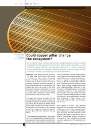
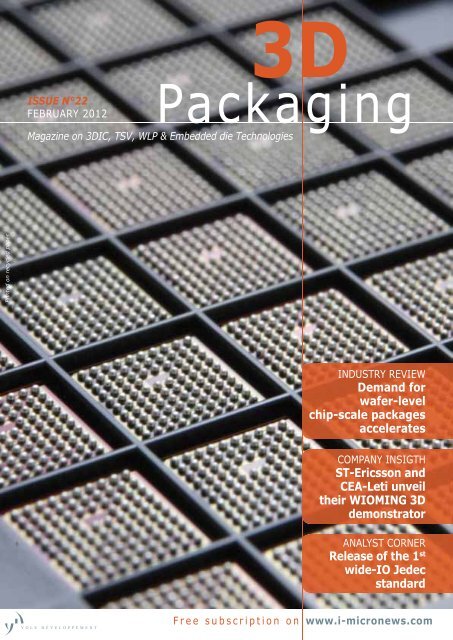
INDUSTRY REVIEW<br />
Demand for<br />
wafer-level<br />
chip-scale packages<br />
accelerates<br />
COMPANY INSIGTH<br />
ST-Ericsson and<br />
CEA-Leti unveil<br />
their WIOMING <strong>3D</strong><br />
demonstrator<br />
ANALYST CORNER<br />
Release of the 1 st<br />
wide-IO Jedec<br />
standard<br />
Free subscription on www.i-micronews.com
<strong>3D</strong> Packaging…<br />
in <strong>3D</strong>!<br />
Finally, a One-on-one<br />
Networking Event for<br />
<strong>3D</strong> & Wafer-level Packaging<br />
The world of device manufacturing is in a rapid state of transformation—<br />
and <strong>3D</strong> & wafer-level packaging is a game-changer of unprecedented scope.<br />
To meet the needs of cost, performance and size, multiple solutions are<br />
emerging for wafer-level packages encompassing several technology platforms.<br />
The result? An entire global supply chain dedicated to <strong>3D</strong> integration of IC<br />
chips is emerging, as the semiconductor IC community has grown to accept<br />
<strong>3D</strong> integration as an alternative to scaling. The question is no longer why <strong>3D</strong>?<br />
Today, the question is how, where, when <strong>3D</strong>…and with whom? To become a<br />
part of the <strong>3D</strong> development vanguard, it's imperative that you meet and engage<br />
the emerging innovators at Connect in <strong>3D</strong>. Collaboration Summits SM are<br />
unsurpassed in delivering hours of networking opportunities in a variety of<br />
pre-scheduled, formal and informal formats with a minimum of 'pre-packaged'<br />
content. Need proof? Look no further than our unprecedented 100% satisfaction<br />
ratings from previous attendees.<br />
More Than 600 Meetings Over Two Days!<br />
The Connect in <strong>3D</strong> Collaboration Summit, presented by Yole Développement,<br />
the world leader in technology information, provides the freedom to meet, learn,<br />
talk, and collaborate in a casual environment. Meet with the leaders from across<br />
the <strong>3D</strong> packaging value chain for two full days. Your time will be fi lled with<br />
“speed-dating-like” sessions and more in-depth one-on-one meetings—meetings<br />
that you control.<br />
Mark your calendar today!<br />
For information and to register, visit www.Connect-in-<strong>3D</strong>.com or<br />
contact Brian Perkins, bperkins@HighlinerEvents.com, +1 207-799-1356.<br />
OCTOBER 31–NOVEMBER 1, 2012<br />
WESTIN MISSION HILLS RESORT & SPA<br />
PALM SPRINGS, CA
F E B R U A R Y 2 0 1 2 I S S U E N ° 2 2<br />
E D I T O R I A L<br />
<strong>3D</strong> comes true in 2012!<br />
If there were any 2012 prophecy I could believe, it is the promise of<br />
a year rich with <strong>3D</strong> packaging announcements and product releases.<br />
Here’s a short-yet-major announcement which, to be honest, I’m surprised<br />
has not made a bigger buzz yet: for the first time ever, a commercial<br />
product has been announced with through silicon vias (TSVs) in a CMOS<br />
logic integrated circuit (IC). The IC is a smartphone application processor<br />
and the TSVs are meant to connect it directly to its overlying DRAM<br />
memory via a so-called wide-IO bus. This announcement was made on<br />
January 18, 2012 by Renesas at ICP - the Integrated Circuit Packaging<br />
conference in Tokyo.<br />
…It’s a fact that<br />
<strong>3D</strong> is getting more<br />
real every day…<br />
e v e n t s<br />
• MEPTEC – The Heat is On<br />
March 19 – San Jose, CA<br />
• Semicon China<br />
March 20 to 22 – Shanghai, China<br />
• Image Sensors 2012<br />
March 20 to 22 - London, UK<br />
platinum partners:<br />
It’s a fact that <strong>3D</strong> is getting more real every day. Last October, Xilinx<br />
announced the product launch of the virtex-7 family of FPGAs with up<br />
to six large CMOS and memory dies assembled side-by-side on a huge<br />
silicon interposer. Last December, Jedec released its first standardization<br />
document concerning the operation protocol and aspects of the physical<br />
layout for so-called “wide-IO interfaces”, which are used to stack large<br />
data bus (512 bits) DRAMs onto their interfacing logic chips, necessitating<br />
TSV in the logic IC, so as to reach unprecedented data bandwidths and<br />
to limit the DRAM power consumption altogether.<br />
But the news didn’t stop there. Not even a month later, Renesas<br />
Electronics announced that volume production of devices following wide-<br />
IO architecture will begin as soon as 2013. Concurrently, ST-Ericsson<br />
also claim successful demo chips based on wide IO and <strong>3D</strong> integration.<br />
One can reasonably assume that if the industry keeps up with this pace<br />
of announcements and product releases related to <strong>3D</strong>, we can expect<br />
that many bold product designs and innovations will materialize by the<br />
end of the year. We intend to continue addressing every advanced<br />
packaging topic in 2012, not just <strong>3D</strong> integration by means of TSVs. A lot<br />
is happening within the scope of wafer-level packaging, flip chip and chip<br />
embedding, to name just a few. For example, in 2011 Texas Instruments<br />
industrialized their MicroSiP packaging concept based on chip embedding<br />
in substrate, and STEricsson seemed only weeks away from releasing<br />
their first fan-out WLP product.<br />
In this February issue we’ll focus on industrial facts, in order to bring<br />
a balanced and complementary viewpoint to offset our self-proclaimed<br />
R&D-enthusiast bias. On example of this are the articles in this issue on<br />
the evolution of fan-in WLCSP, its infrastructure and market, and how it<br />
went from being considered an advanced technology differentiator to a<br />
“must-have” industry standard in just a few years.<br />
Jean-Marc Yannou,<br />
Senior Analyst, Advanced Packaging,<br />
Yole Développement<br />
yannou@yole.fr<br />
3 D P a c k a g i n g 3
F E B R U A R Y 2 0 1 2 I S S U E N ° 2 2<br />
C O N T E N T S<br />
INDUSTRY REVIEW 6<br />
• Demand for wafer-level chip-scale packages accelerates<br />
COMPANY INSIGHT 10<br />
• ERS: High tech thermal solutions coming from southern Germany<br />
for the world market<br />
• Palomar Technologies Assembly Services discusses the value<br />
of automation for ultra high-precision applications<br />
(Courtesy of ASE Global)<br />
• AT&S has taken dramatic stepsto bring ECP ® to market,<br />
and now things are starting to warm up<br />
• ST-Ericsson and CEA-Leti’s WIOMING prototype shows how to combine<br />
wide IO memory and logic SoC for future <strong>3D</strong> multi-processor architectures<br />
ANALYST CORNER 20<br />
• Market dynamics impact WLCSP adoption<br />
• WLCSP market trends to watch in 2012<br />
• Moving <strong>3D</strong> IC forward with the standardization of wide IO DRAM<br />
WHAT’S INSIDE? 26<br />
OmniVision’s VGA wafer-level camera<br />
FROM I-MICRONEWS.COM<br />
Stay connected with your peers<br />
on i-<strong>Micronews</strong>.com<br />
Please visit our website to discover the<br />
last top stories in Advanced Packaging:<br />
With 22,000 monthly visitors,<br />
i-<strong>Micronews</strong>.com provides for Advanced<br />
Packaging area: current news, market<br />
& technological analysis, key leader<br />
interviews, webcasts section, reverse<br />
engineering / costing, events calendar,<br />
latest reports …<br />
> TSMC plans 3-D IC assembly launch<br />
early in 2013<br />
> First major <strong>3D</strong> TSV wide-IO product<br />
announcement is made by Renesas<br />
> STATS ChipPAC packaging evolution<br />
to 2.5/<strong>3D</strong>: a closer look<br />
GOLD PARTNERS:<br />
4 3 D P a c k a g i n g
Solid State Equipment LLC<br />
ADVANCED PACKAGING<br />
SINGLE WAFER<br />
WET PROCESSING<br />
TSV CLEAN AND RESIST STRIP<br />
As received – post DRIE After SSEC Cleaning As received – post DRIE After SSEC Cleaning As received – post DRIE After SSEC Cleaning<br />
Si ETCH TO REVEAL Cu TSV<br />
DRY FILM STRIP<br />
Optical SEM ISIS <strong>3D</strong><br />
FLUX CLEANING<br />
ADVANCED PACKAGING SINGLE WAFER WET PROCESSING<br />
UBM AND RDL METAL ETCH<br />
Undercut vs Etch Time<br />
Undercut (µ)<br />
1.7µ<br />
1.5µ<br />
0µ<br />
(non-measurable)<br />
WaferChek +15 sec +30 sec<br />
Over-etch Over-etch<br />
Etch Time<br />
Before Etch<br />
After UBM Etch<br />
ssecusa.com<br />
© 2011 SOLID STATE EQUIPMENT LLC<br />
SSE_345_MicroNews AdV3.indd 1<br />
10/20/11 3:11:03 PM
F E B R U A R Y 2 0 1 2 I S S U E N ° 2 2<br />
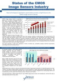
INDUSTRY REVIEW<br />
Examples of WLCSPs made by ASE<br />
(Courtesy of ASE)<br />
Demand for wafer-level chip-scale<br />
packages accelerates<br />
Wafer-level chip-scale packages (WLCSPs) are by no means the lowest-cost solution<br />
available, but its tiny volume and electrical performance benefits are turning it into<br />
the “go-to” package for use in mobile phones and tablets.<br />
For insiders’ perspective into the WLCSP<br />
market, we turned to Advanced Semiconductor<br />
Engineering, Fairchild Semiconductor, FlipChip<br />
International, Teramikros, and VTI Technologies.<br />
Growth ahead<br />
WLCSP technology is constantly evolving—not<br />
necessarily in groundbreaking ways, but to<br />
meet different increasing demands and subtle<br />
variations in the thickness of the material,<br />
material compositions, structures, and sizes for<br />
new applications.<br />
While it’s now being produced in much greater<br />
volume, it is important to point out that there is no<br />
standard WLCSP. There are tremendous variations<br />
in WLCSP because each customer has specific<br />
application requirements.<br />
“Our customers have been saying for the past 6<br />
months that the growth of WLCSP is accelerating,”<br />
says John Hunt, director of engineering at ASE.<br />
“Many packages are being transitioned to WLCSP,<br />
and one customer is moving an entire family of flip<br />
chip CSP into WLCSP. We’re also seeing more analog<br />
and power management going into WLCSP. I expect<br />
it to pick up—we’ve put in additional capacity for<br />
300-mm analog.”<br />
Ted Tessier, FlipChip International’s chief<br />
technical officer, believes WLCSP growth will<br />
continue to increase during the next 5 years as<br />
new applications emerge that will benefit from the<br />
minimal form factor possibilities of this technology.<br />
“Emerging applications like image sensor packages,<br />
MEMS packaging, as well as stacked die solutions,<br />
will emerge in the industry. Fan-out packaging<br />
technologies, either wafer-level or embedded-diein-laminate<br />
approaches, will continue to leverage<br />
the installed supplier base put in place for waferlevel<br />
packaging (WLP) technologies,” he notes.<br />
“I expect the technology to continue to grow. Fanin<br />
WLP is mature, but there are emerging new<br />
technologies that are still somewhat immature,”<br />
says Heikki Kuisma, director of advanced<br />
development at VTI Technologies.<br />
6<br />
3 D P a c k a g i n g
I S S U E N ° 2 2 F E B R U A R Y 2 0 1 2<br />
Examples of WLCSPs made by ASE<br />
(Courtesy of ASE)<br />
From Fairchild Semiconductor’s perspective,<br />
Yong Liu, senior member technical staff, and<br />
Jifa Hao, technical staff member, concur that<br />
they expect growth for WLCSP power devices<br />
to continue at the same or an even faster<br />
pace, thanks to its primary advantages: small<br />
package size, minimized IC to PCB inductance,<br />
and shortened manufacturing cycle time.<br />
“WLCSP has been primarily applied to small<br />
(< 3 mm 2 ) to medium (3-5 mm 2 ) chip sizes,”<br />
says Takeshi Wakabayashi, Teramikros’<br />
general manager, development division. “We<br />
expect it to also penetrate to large chip sizes,<br />
such as 5 mm 2 , or larger as well, increasing<br />
the growth rate of WLCSP market.” He expects<br />
WLCSP to ultimately become the dominant<br />
packaging design in the future.<br />
For the moment, WLCSP technology for I/O<br />
counts of less than 50 is considered by most<br />
to be mature. There is, however, plenty of<br />
activity underway in the industry to extend<br />
board-level reliability of WLCSP packages to<br />
array sizes in the 100 – 200 I/O range—while<br />
achieving acceptable reliability. There are<br />
opportunities for improvements in this area<br />
and for broadening the application envelope<br />
to these higher I/O counts.<br />
Liu and Hao note that WLCSP requires waferlevel<br />
equipment and high automation, and<br />
that the reason some OEMs are reluctant to<br />
use WLCSP is because it involves a solder<br />
bumping process that’s quite different from<br />
the traditional wafer-level device process.<br />
Interestingly, as Wakabayashi points out,<br />
it’s becoming more important to make PCBs<br />
smaller to secure and maximize space for<br />
the battery because it directly determines<br />
the competitiveness of smartphones. “Since<br />
WLCSP is truly a chip-size package, it’s the<br />
package type of choice to fight for limited<br />
space,” he explains. “Unfortunately, however,<br />
some OEMs had a bad experience with<br />
unsuitable WLCSPs with reliability issues.<br />
Their smartphones were susceptible to<br />
damage from being dropped. We can’t stress<br />
enough the importance of selecting the right<br />
WLCSP.”<br />
Fan-out WLCSP and chip<br />
embedding in substrates<br />
Can fan-out WLCSP or chip embedding in<br />
substrates supplement adoption of WLCSP<br />
in the near future? The general consensus<br />
is yes, but the timeline for this happening<br />
remains unclear.<br />
Tessier believes that IC modification to<br />
prepare devices for embedding in fan-out<br />
WLCSP or embedded die in PCB substrates<br />
will grow in popularity over the next few years<br />
because fine-line redistribution layers (RDL) is<br />
most effectively carried out at the wafer-level<br />
to minimize per die costs associated with die<br />
preparation for embedding.<br />
Kuisma notes that the scope of fan-out WLP<br />
will remain more limited than ordinary WLCSP.<br />
“But for us, this is a very interesting technology<br />
that we need to look at closer,” he adds.<br />
“With the advent of more SMT-compatible<br />
underfill processes, WLP solutions involving<br />
larger array sizes are enabled. Without these<br />
underfill advances, the board-level reliability<br />
of such large arrays wouldn’t be adequate for<br />
smartphone applications,”<br />
says Ted Tessier, FlipChip International.<br />
Both fan-out and embedding can supplement<br />
WLCSP, according to Hunt. “There are reasons<br />
to go to fan-out WLCSP, such as when you can’t<br />
fit all of the I/O onto a package at wafer-level.<br />
WLCSP is a less expensive solution, so you<br />
wouldn’t use fan-out WLCSP if you don’t need<br />
it. It can, however, supplement applications<br />
for which WLCSP isn’t suitable,” he elaborates.<br />
“And chip embedding actually uses a WLCSP<br />
inside. Customers are beginning to ask us<br />
to prepare the die before embedding—which<br />
means putting copper RDL and under bump<br />
metallization (UBM), one or both, on the<br />
die before they embed them. This is a new<br />
application for wafer-level processing.”<br />
Is adoption of WLCSP<br />
OEM dependent?<br />
Adoption of WLCSP into smartphone applications<br />
varies widely from one OEM to the next, but<br />
its smaller package form factor is behind its<br />
adoption by most.<br />
Some OEMs have been reluctant to adopt<br />
wide-scale use of WLCSPs, primarily because<br />
of board-level concerns related to the largearray-sized<br />
devices, according to Tessier.<br />
“With the advent of more SMT-compatible<br />
underfill processes, WLP solutions involving<br />
larger array sizes are enabled. Without these<br />
underfill advances, the board-level reliability<br />
of such large arrays wouldn’t be adequate for<br />
smartphone applications,” he says.<br />
3 D P a c k a g i n g<br />
(WLCSP Market & Industrial Trends report, January 2012, Yole Développement)<br />
7
F E B R U A R Y 2 0 1 2 I S S U E N ° 2 2<br />
And as the industry moves down to 0.3 and<br />
0.25 mm, it’s possible to fit higher I/O counts<br />
onto the die. So some of the devices that<br />
today need it fan-out or embedding won’t<br />
with the move to finer pitches. You’ll still be<br />
able to use a WLCSP—assuming reliability<br />
requirements can be met.<br />
Expansion to other applications<br />
WLCSPs aren’t just for smartphones and<br />
tablets—the technology is starting to make<br />
headway into automotive, medical and more<br />
MEMS applications.<br />
“We’re observing the wide adoption of<br />
WLCSPs beyond smartphone applications,<br />
such as analog and power for industrial use,<br />
in addition to medical and automotive,” says<br />
Wakabayashi.<br />
On the medical end of things, Kuisma sees<br />
WLCSP use primarily in implantable devices<br />
like pacemakers.<br />
The automotive industry is also trying to<br />
shrink down their electronics. “During the past<br />
6–9 months we’ve seen increased interest in<br />
power control modules and analog devices<br />
for WLCSP, whereas it was previously RF and<br />
digital applications,” explains Hunt. “This<br />
increase isn’t necessarily under the hood; a<br />
tremendous number of electronics go into the<br />
body of the car—for navigation, radios, and<br />
satellite communication.”<br />
5–6 years, according to Tessier. “With the<br />
wide-scale adoption of polybenzoxazole (PBO)<br />
dielectrics and thick-plated copper RDL and<br />
UBM structures, a package solution is available<br />
to support WLCSP applications as they migrate<br />
from ELK to ULK constructions,” he adds.<br />
Advantages of WLCSP in CMOS<br />
image sensors and MEMS<br />
What are the advantages of using WLCSPs in<br />
image sensors and MEMS?<br />
From VTI’s perspective, mechanical stress<br />
on MEMS is the most important thing. This is<br />
much lower with WLCSP than with QFN/LGA,<br />
explains Kuisma. “Size is the next advantage.<br />
Avoiding wire bonds with increasing gold prices<br />
is also important. Note: ultrasonic wire bonding<br />
is always tricky with MEMS, especially copper<br />
bonding with much higher energy. Further, our<br />
way of stacking dies in WLCSP leads to very<br />
low parasitics and good immunity to EMI. We<br />
expect that more MEMS manufacturers will<br />
eventually shift to WLCSP. Cost-wise, wire<br />
bonding and QFN/LGA are equal to WLCSP in<br />
MEMS applications,” he adds.<br />
“It depends on your definition of WLCSP, but<br />
we’re seeing more and more requests for <strong>3D</strong><br />
and MEMS processing of packages in waferlevel<br />
format,” says Hunt. “The smallest MEMS<br />
reduce the size, which is always desirable.<br />
Most image sensors, or at least many of them,<br />
are wafer level.”<br />
VTI’s CMR3100 is the world’s smallest<br />
gyroscope, at 3x3 mm 2 , and it relies on WLCSP.<br />
(Courtesy of VTI)<br />
bumped devices. The added stand-off possible<br />
with a WLCSP structure allows for ease of<br />
underfilling as well as for ease of molding<br />
with concurrent underfilling with molding<br />
compound. Smaller stand-off flip chip bumps<br />
may provide additional challenges.”<br />
WLCSP is fundamentally different than flip<br />
chip, according to Wakabayashi, although he<br />
views some types of WLCSP as very similar.<br />
“WLCSP doesn’t require expensive flip chip<br />
bonders and can be mounted with conventional<br />
SMT machines. Flip chip also requires very<br />
costly underfill,” he says. “WLCSP with 0.25-<br />
mm or even 0.20-mm pitch can be mounted<br />
with high-speed SMT machines and general<br />
reflow processes. In the case of low-k devices,<br />
which are so fragile, handling of bare chips is<br />
extremely difficult and costly.”<br />
Other WLCSP trends<br />
One WLCSP manufacturing trend is that while<br />
it’s still primarily done in Taiwan, companies<br />
are setting up facilities in other locations such<br />
as Singapore, the Philippines, Korea, Portugal,<br />
and China.<br />
“Customers are beginning to ask us<br />
to prepare the die before embedding,”<br />
says John Hunt, ASE.<br />
Opportunities for WLCSP expansion to<br />
automotive and high-power computing aren’t<br />
as good as applications like smartphone<br />
and tablets, Liu and Hao caution, due to the<br />
high current density, high power, and heat<br />
dissipation factors. However, for lower-power<br />
applications such as point-of-load switch, buck<br />
converter, and smart integration of analog, logic<br />
and power, they see great opportunities ahead.<br />
Migration to new CMOS<br />
technologies’ impact on WLCSP<br />
Is the migration to new CMOS technologies<br />
helping or hindering adoption of WLCSP? Are<br />
new technologies necessary for ELK and ULK<br />
layers?<br />
The migration to new CMOS technologies seems<br />
to be compatible with improvements that have<br />
occurred in WLCSP packaging over the past<br />
8<br />
WLCSP vs. flip chip<br />
There’s a clear trend of significant pitch<br />
reduction. Why are WLCSPs used rather<br />
than flip chips (even though WLCSPs can be<br />
considered flip chips)?<br />
Although the industry dabbles with 0.3mmand<br />
0.25-mm-pitch WLCSPs, cell phone<br />
OEMs are generally not equipped to perform<br />
such fine-pitch assembly at the PCB level.<br />
“Virtually all 0.3-mm WLCSPs shipped today<br />
are used in modules or system-in-package<br />
(SiP) applications, where they’re assembled<br />
more like coarse-pitch flip chip components<br />
rather than SMT components,” says Tessier.<br />
“Generally, if these components are available<br />
in a WLCSP format, the end user will attempt<br />
to use these packages rather than redesign<br />
the parts to slightly finer-pitch flip chip<br />
“All of ASE’s WLCSP are in Taiwan. But we’re<br />
increasingly facing low-cost competitors in<br />
China,” notes Hunt.<br />
Another more obvious trend: The relentless push<br />
toward thinner WLCPS. With discrete packaging<br />
continuing to produce thinner interconnects,<br />
capacitors, and resistors, WLCSPs need to be<br />
continuously thinned down to match these<br />
thickness reductions—with target thicknesses<br />
changing every 3 months.<br />
And the industry is also working hard to<br />
find ways to make larger WLCSPs for power<br />
modules as reliable as smaller ones—at high<br />
power, with thicker RDLs, and improved power<br />
distribution—at a lower cost. So the goal is<br />
to find ways to achieve all of this without<br />
sacrificing reliability.<br />
Sally Cole Johnson<br />
for Yole Développement<br />
3 D P a c k a g i n g
I S S U E N ° 2 2 F E B R U A R Y 2 0 1 2<br />
Jifa Hao, Member of Technical Staff,<br />
Fairchild Semiconductor<br />
Hao is responsible for reliability engineering for technology<br />
development. He received his Ph.D. in physics from State<br />
University of New York at Stony Brook, and has published more<br />
than 25 papers in journals and conference proceedings, and<br />
holds 8 patents (and has 4 patents pending).<br />
John Hunt, Director of Engineering,<br />
Production Promotion, ASE (US)<br />
Hunt provides technical support for the introduction, engineering,<br />
marketing, and business development activities for all advanced<br />
wafer-level packaging technologies at ASE. Prior to joining ASE,<br />
Hunt was technology development manager at ADFlex Solutions,<br />
and research and development engineering manager at both Nortel and Digital<br />
Equipment Corp. He has 40 years’ experience in various areas of manufacturing,<br />
assembly, and testing of electronics components and systems, with emphasis<br />
on the development of new technologies and processes. Hunt holds a BS degree<br />
in chemistry from Rutgers University, and a MS/MBA in industrial engineering<br />
and engineering administration from the University of Central Florida.<br />
Heikki Kuisma, Director of Advanced Development,<br />
VTI Technologies<br />
Kuisma’s responsible for the management of research and<br />
advanced development in the area of MEMS sensors, MEMS<br />
manufacturing technology, packaging of sensors, and sensor<br />
interface circuits. He is also actively participating in the<br />
planning and management of national and European technology programs in<br />
Microsystems and microelectronics.<br />
Yong Liu, Senior Member of Technical Staff,<br />
Fairchild Semiconductor<br />
Liu works in the packaging development group. His main interest<br />
area is advanced analog and power electronic packaging. Liu<br />
holds a Ph.D., is an IEEE senior member, and has co-authored<br />
more than 160 papers in journals/conference proceedings, two<br />
books, and has been granted 25 US patents (and has 18 patents pending).<br />
Ted Tessier, Chief Technical Officer, FlipChip International<br />
Tessier has more than 25 years’ experience in the semiconductor<br />
packaging industry and a comprehensive industry perspective,<br />
based on senior engineering and management positions at<br />
Nortel, Motorola, Biotronik, Amkor, STATS ChipPAC, and FCI.<br />
He has published actively and is well known in the industry for<br />
his work in the areas of advanced packaging technologies, including wafer<br />
bumping, multichip modules/system-in-package technologies, flip chips, <strong>3D</strong><br />
packaging, WLSCPs, and wafer-level processes.<br />
Takeshi Wakabayashi,<br />
General Manager, Development Division, Teramikros<br />
In 1980, he joined Casio Computer, engaged in development<br />
of semiconductor process technology. In 1987, he completed<br />
gold bumping process development for mass-production and<br />
was engaged in development of WLP Technology in 1997. He<br />
started the production of WLP at Casio Micronics Co., Ltd. 4 years later. In<br />
2002, he initiated EWLP development for embedding and completed WLP<br />
process development for 300mm wafer and low-k devices. He has been General<br />
Manager of Teramikros since October 2011. He filed more than 40 patents<br />
on Wafer Bumping, WLP technologies. Actively participating in JEITA, JPCA<br />
standardization activities on embedding technology.<br />
MiNaPAD conference - Grenoble, April 24th 2012<br />
BEYOND 300 mm workshop:<br />
Packaging Challenges and Opportunities<br />
for 450 mm wafers and panel scale solutions<br />
A SEMI event hosted by IMAPS<br />
For more information visit:<br />
www.semi.org/beyond300mm
F e b r u a r y 2 0 1 2 I S S U E N ° 2 2<br />
COMPANY INSIGHT<br />
High tech thermal solutions<br />
coming from southern Germany<br />
for the world market<br />
ERS is a German company, founded in 1970 and specializing in thermal solutions<br />
for the semiconductor industry. Calling itself a “research & development company<br />
with a large production capacity” ERS participates actively in semiconductor<br />
industry events and welcomes thermal challenges that defy standard solutions.<br />
In 2008, engineer Klemens Reitinger took over the company from its founder<br />
Erich Reitinger and launched a program of growth and diversification.<br />
Klemens Reitinger,<br />
Owner & General<br />
Manager, ERS<br />
Yole Développement: Would you please give<br />
us a little background on what you were<br />
doing before you joined ERS and what your<br />
recent focuses at ERS are?<br />
Klemens Reitinger: I joined ERS electronic<br />
GmbH in February of 1992 having graduated as an<br />
engineer of fine mechanics in Vienna. I worked in<br />
almost every department within the ERS factory<br />
including manufacturing, R&D and customer<br />
support before taking over as general manager<br />
in 2001. In June 2008 I took ownership of the<br />
company and began a program of growth and<br />
diversification including starting two completely<br />
new product groups – FOWLP (eWLB) tools and<br />
hot/cold thermal systems for final test.<br />
YD: ERS is a technology leader in thermal<br />
wafer test equipment dedicated to the<br />
semiconductor wafer production since 1970.<br />
Could you introduce to our readers ERS’s<br />
products and activities?<br />
KR: ERS was founded by my uncle, Erich Reitinger,<br />
in 1970 and is now based in the Munich suburb<br />
of Germering, Germany. We have approximately<br />
45 employees generating approximately Euro 10M<br />
in annual revenue. ERS has a world-wide support<br />
network with offices in Dresden, in Charlotte,<br />
North Carolina and in Dallas, Texas as well as sales<br />
and service partners in Asia.<br />
Our core competency is in thermal equipment<br />
and our main products are thermal chucks used<br />
in probing tools for semiconductor wafers. In<br />
the 1970’s we introduced what we believe was<br />
the very first thermal chuck for wafer test - a<br />
2-inch Peltier-controlled unit. Since then we have<br />
researched, developed and manufactured multiple<br />
applications of temperature creation and control.<br />
By the middle of the 1990’s, we had determined<br />
that using air as the sole coolant in ERS thermal<br />
units was the future direction of the company.<br />
Thermal systems using air as the only coolant have<br />
the highest uptime and the lowest running costs in<br />
the industry and taking this decision enabled us to<br />
take a very strong position in a market ever more<br />
dependent on reliability and cost control. Many of<br />
our products, especially the AirCool plus system,<br />
flew in the face of conventional wisdom in terms of<br />
what was possible and not possible with air cooling.<br />
We have delivered thermal chucks systems using<br />
only air as the coolant with operating temperature<br />
ranges of -65°C to 500°C.<br />
YD: Could you tell us what the main<br />
requirements for fan-out WLP de-bonder<br />
tools are in terms of thermal accuracy and<br />
reliability for eWLB applications?<br />
ERS’s ADM 300 eWLB debonding system (Courtesy of ERS)<br />
KR: The key features of our fan-out WLP auto debonder<br />
are based on the patented processes we<br />
empirically developed over many months. These<br />
processes include the safe removal of the carrier,<br />
the clean de-taping and the extremely critical,<br />
controlled cool-down of the reconstituted wafer<br />
after de-bonding/de-taping. Air-cooled chucks in<br />
the system are the basis of its inherent reliability<br />
and the thermal control of those chucks is a direct<br />
derivative of our experience in wafer test. The suite<br />
10<br />
3 D P a c k a g i n g
By Courtesy of CEA LETI and Novapack<br />
By Courtesy of ST Microelectronics and CEA LETI<br />
I S S U E N ° 2 2 F E B R U A R Y 2 0 1 2<br />
of production features in the system comes<br />
from customer input and includes wafer<br />
marking, de-flash and warpage monitoring.<br />
YD: Do you consider providing equipment<br />
to process future 450 mm wafers?<br />
KR: Yes, definitely. ERS is already<br />
developing 450 mm air-cooled thermal chuck<br />
technology for future 450 mm silicon wafer<br />
test applications. As for the eWLB de-bonding<br />
tools, the trend seems to be in the direction<br />
of rectangular panels with form factors in<br />
discussion that would exceed the area of a<br />
450mm wafer. We have already built the first<br />
engineering tool for these larger panels and<br />
have requests for tests to be performed on<br />
them at the FOWLP competency center in our<br />
factory.<br />
YD: According to you, what are the main<br />
key features and advantages of the Fanout<br />
wafer level packaging (also known as<br />
eWLB technology) compared to standard<br />
embedded wafer-level-packages? How<br />
do you explain the different motivations<br />
and drivers for eWLB?<br />
KR: This is difficult for us as a tool vendor to<br />
judge. Here are some of the answers that we<br />
hear in the marketplace when we pose that<br />
question to our customers:<br />
• Suitable for multi-chip and system-inpackage<br />
applications<br />
• Maintain the same socket size through<br />
silicon shrink generations<br />
• Short signal path for improved high<br />
frequency performance<br />
• Very good thermal performance<br />
• Lower material costs through “batchwiring”<br />
• The opportunity to use existing front-end<br />
tools for the redistribution layer (RDL)<br />
• Very thin package size<br />
• Small footprint package size<br />
YD: Could you update us on what is<br />
coming up on the R&D front at ERS?<br />
KR: As mentioned, we are already working<br />
on air-cooled 450mm thermal chuck systems.<br />
Our current line of wafer thermal chucks is<br />
now completely modular in manufacture, onsite<br />
service and upgrading.<br />
As for FOWLP, we continue to research<br />
de-bonding, adhesive removal and shapecontrol<br />
solutions for new applications using<br />
new molding materials, adhesives, substrate<br />
sizes and methods. This is being done in<br />
cooperation with some 15 different industry<br />
partners at our FOWLP competency center in<br />
our factory.<br />
In the back end, we are now working on a<br />
general, air-only tri-temp solution (no liquid<br />
nitrogen necessary) for the final test of<br />
packaged semiconductor devices.<br />
YD: What makes your ERS equipment<br />
stand out versus competitors?<br />
KR: We are a team of problem-solvers<br />
including experts in thermo-dynamics, fine<br />
mechanics, electronics test engineering,<br />
software and system integration. Because<br />
we have our own CAD/CAM manufacturing<br />
capability we have access to same-day<br />
prototyping so we can move quickly. What<br />
really sets us apart from other high-tech<br />
companies, however, is the fact that we set<br />
temperature in the center of the problemsolving<br />
process. I believe that is what really<br />
makes us stand out from the others.<br />
www.ers-gmbh.de<br />
1events<br />
AFF 2011 BLEUE:Mise en page 1 30/01/2012 14:57 Page<br />
INTERNATIONAL MICROELECTRONICS AND PACKAGING SOCIETY<br />
IMAPS France - 49 rue Lamartine - 78035 Versailles<br />
Tel : +33 (0)1 39 67 17 73 – Fax : +33 (0)1 39 02 71 93<br />
imaps.france@imapsfrance.org www.france.imapseurope.org<br />
MiNaPAD Forum 2012<br />
2 nd Micro/Nano-Electronics Packaging and Assembly,<br />
Design and Manufacturing Forum<br />
Conference & Exhibition<br />
• The 2 nd MiNaPAD Forum (Micro/Nano-Electronics Packaging and<br />
Assembly and Manufacturing and Design Forum) will be held at the<br />
Minatec campus in Grenoble on April 24-26. The event will begin on April<br />
24 with a workshop Beyond 300mm sponsored by SEMI and hosted by<br />
IMAPS. The MiNaPAD conference and exhibition will then be held on April<br />
25-26. The final program and registration forms will be available at the<br />
end of February.<br />
By Courtesy of Ansoft<br />
April 24 – Beyond 300mm Workshop<br />
SEMI event hosted by IMAPS<br />
April 25-26 – Conference & Exhibition<br />
For further information, please refer to the website<br />
http://france.imapseurope.org<br />
or contact Florence VIRETON at +33(0) 1 39 67 17 73<br />
or by e-mail: imaps.france@imapsfrance.org<br />
(Click on the tab Prochainement/Next)<br />
Photo : Nicole Salvat<br />
« Bringing closer the design<br />
and the semiconductor assembly & packaging communities »<br />
Partners<br />
Media Sponsors<br />
IMAPS France<br />
49 rue Lamartine - 78035 Versailles - France<br />
Tel : +33 (0)1 39 67 17 73 - Fax : +33 (0)1 39 02 71 93<br />
imaps.france@imapsfrance.org - www.france.imapseurope.org<br />
3 D P a c k a g i n g
F e b r u a r y 2 0 1 2 I S S U E N ° 2 2<br />
COMPANY INSIGHT<br />
Palomar Technologies Assembly<br />
Services discusses the value of<br />
automation for ultra high-precision<br />
applications<br />
With the ever-evolving trend for smaller applications, the capability to produce<br />
high-precision, high-reliability bonding remains imperative.<br />
Donald Beck,<br />
General Manger, Palomar<br />
Technologies Assembly<br />
Services TM<br />
Yole Développement: Could you please tell us<br />
about your past background and career and<br />
about your current assignments at Palomar<br />
Technologies?<br />
Donald Beck: I began my career in the mid-1980s<br />
with a small microelectronic assembly house<br />
in southern California. At that time, automated<br />
wire bonders had just been introduced; I could<br />
actually complete a part manually faster than<br />
a machine could do it at that time! In 1989, I<br />
joined a new team focused on HTCC packaging.<br />
This particular role rendered a lot of knowledge<br />
about the microelectronics industry, specifically<br />
in Asia. Prior to joining Palomar Technologies, I<br />
worked at a Florida-based company for 12 years<br />
where I focused on classified complex assemblies.<br />
In 2004, I joined Palomar as a Senior Applications<br />
Engineer and within the first year became<br />
Applications Manager. I quickly noticed that all<br />
the key elements for contract microelectronic<br />
assembly existed, so I lobbied to evaluate creation<br />
of Palomar Technologies Assembly ServicesTM<br />
(previously Palomar Microelectronics). In 2008, I<br />
became General Manager of Assembly Services.<br />
Coupled Capacitor on Die (COD) for Microelectronic<br />
Circuits; Lightweight Modular Antenna Assembly<br />
having RF Amplifier Modules Embedded in<br />
Support Structure Between Radiation and Signal<br />
Strength Distribution Panels; High Frequency,<br />
Low Temperature, Thermosonic Ribbon Bonding<br />
Process for System Level Applications; Method for<br />
Removing Microelectronic Substrates 1; Method<br />
for Removing Microelectronic Substrates 2.<br />
YD: How would you define Palomar Technologies<br />
as a company in just a few words?<br />
DB: Palomar today is a company committed to both<br />
ingenuity and integrity. When our team commits<br />
to new application development—be it a new die<br />
attach platform or new assembly technology—we<br />
always honor our word and produce products we’re<br />
proud to stamp our name on. We never dismiss the<br />
importance of every customer we work with, which<br />
is demonstrated through our long list of recurring<br />
business opportunities around the globe.<br />
YD: How would you like to define Palomar<br />
Technologies in just a few words in 2015?<br />
I’ve published several technical papers and articles<br />
including “The Great Debate: Ball vs. Wedge” and<br />
“Automated Precision Assembly for High-Volume<br />
HB LEDs”. I also currently hold five patents: Closely<br />
DB: By 2015, I would expect that our Assembly<br />
Services division would support the majority of<br />
our growing world-wide customer base and to<br />
further define the unique and invaluable offerings<br />
Palomar has as the only OEM who can service<br />
all microelectronic needs through both capital<br />
equipment and in-house precision microelectronic<br />
assembly.<br />
YD: How are your product lines structured,<br />
and which is your best selling product family?<br />
6500 Die Bonder cleanroom (Courtesy of Palomar Technologies)<br />
12<br />
DB: The 3800 Die Bonder, introduced in 2010, is<br />
a leading solution. This large 0.9017 x 0.508 m 2<br />
(35.5 x 20 inch) work area die bonder offers ultra<br />
flexibility in application production, whether you<br />
require epoxy die attach, pulsed heat eutectic<br />
attach or a full-production in-line assembly. The<br />
3800 Die Bonder offers a multitude of solutions<br />
on a single platform—truly the “Swiss Army Knife”<br />
of die bonders. Our 6500 Die Bonder is an ultrahigh<br />
placement accuracy pick-and-place machine,<br />
3 D P a c k a g i n g
I S S U E N ° 2 2 F e b r u a r y 2 0 1 2<br />
which also has wafer level packaging (WLP)<br />
configuration. Our 8000 Wire Bonder—a<br />
large area, high-reliability wire bonder and<br />
ball bumper with deep access capabilities—<br />
complements our die attach equipment.<br />
Augmenting our systems is our Customer<br />
Services (Field Service support, Process<br />
Development Consulting and bonder training<br />
courses). With Assembly Services, customers<br />
gain the unique ability to prototype and<br />
develop critical processes and materials with<br />
an OEM, utilizing highly skilled engineers<br />
and the most advanced process tools; thus<br />
reducing risk and shortening time-to-market<br />
for today’s leading-edge applications.<br />
YD: Which share of your Palomar’s<br />
revenues can be attributed to advanced<br />
semiconductor packaging?<br />
DB: The majority of Palomar’s end application<br />
development can be classified as “advanced”<br />
or “complex”. “Electronics assembly” can<br />
umbrella many organizations and OEMs, but<br />
there is a component of that group into which<br />
Palomar falls that does the really difficult<br />
“stuff”, such as odd-form deep access<br />
wire bonding, high-accuracy wafer level<br />
packaging, or even highly secured assembly<br />
services laboratories with computerized<br />
production monitoring and management.<br />
YD: What is the average life cycle time<br />
of your equipment? How much of the<br />
company’s revenue do you reinvest for<br />
R&D?<br />
DB: Today, we know of many Palomar systems<br />
reaching decades of longevity and peak<br />
performance. Our Field Services engineers<br />
and Process Development Consultants enable<br />
the success of our legacy equipment. We are<br />
often creating that next “big thing” through<br />
process development and prototyping with<br />
our customers in our Assembly Services<br />
laboratories.<br />
YD: “High-precision” seems to be a<br />
keyword of Palomar’s product offering. Do<br />
you think that even finer accuracies will<br />
be needed in the future? Can you please<br />
give us some application examples?<br />
DB: Today, almost all of our Assembly<br />
Services opportunities stem through the need<br />
for high accuracy. We see this especially in<br />
photo diode and laser module designs. We’re<br />
beginning to see a need for
F E B R U A R Y 2 0 1 2 I S S U E N ° 2 2<br />
YD: Silicon photonics seems to be booming again for the first<br />
time since the 2000 slump. Are you confident that this will be<br />
a long-term opportunity for Palomar?<br />
DB: Palomar believes that whenever customers need the highprecision<br />
pick-and-place requirements for opto-electronic<br />
assemblies, we have a superior solution.<br />
YD: Are there cases for which the LED market will require<br />
high accuracy or other differentiating arguments Palomar<br />
can offer? Which ones?<br />
DB: As previously mentioned, we have seen some LED light engine<br />
designs requiring sub-3µm placement requirements. These tend to<br />
be designs with focus lenses so that alignment of the LEDs to the<br />
lens is critical. Another could be through the emergence of Micro-<br />
Ball Grid Arrays (BGAs). As these designs shrink, the need for high<br />
accuracy will grow. We see this today with some surface mount<br />
assemblies where an SMT assembler can support all needs up<br />
until the Micro-BGA when they seek support through our Assembly<br />
Services division. These applications are some of the leading<br />
applications for our 6500 Die Bonder platform.<br />
YD: What are Palomar’s current focuses in R&D?<br />
How the mobile<br />
industry has<br />
grown a $1B+<br />
semiconductor<br />
packaging<br />
platform?<br />
DB: Palomar works with a broad range of customers to meet their<br />
assembly challenges. We continually develop and improve both<br />
machines and processes to improve our customers’ return on<br />
investment.<br />
www.palomartechnologies.com<br />
Donald Beck, General Manger, Palomar Technologies Assembly<br />
Services TM , Palomar Technologies<br />
Donald Beck has led the Assembly Services division at Palomar Technologies<br />
since 2008, expanding it from a "tiger team" to a major player in precision<br />
microelectronics contract assembly. Under Mr. Beck’s tenure, Assembly<br />
Services continues to develop new processes and solutions for customers<br />
worldwide.<br />
A three-decade microelectronics industry veteran, Mr. Beck began his<br />
career at in southern California, developing high-reliability, Class B military,<br />
prototype thick film memory modules. In 1989, Mr. Beck worked with a new<br />
team to qualify and manage all assembly activity for on-shore and off-shore<br />
subcontract suppliers. During this time, he developed assembly techniques<br />
for Cofire Ceramic and Thin Film MCMs. Mr. Beck later become Lead Engineer<br />
of Advanced Manufacturing for a Florida-based company. In this new role,<br />
he not only engineered complex military packages, but also managed a<br />
large microelectronic assembly supply chain. Mr. Beck joined the Palomar<br />
Technologies team in 2004 to run the Applications Division, holding the title of<br />
Senior Applications Engineer. At Palomar, he developed ball bump applications,<br />
automated interconnect processes including an automated part pass through<br />
system (for automotive customers), and an ultra-fine pitch (60um-70um)<br />
interconnection processes for complex MCM applications. Soon after the start<br />
of his career at Palomar, Mr. Beck was named General Manager of Palomar<br />
Technologies Assembly ServicesTM.<br />
14<br />
WLCSP<br />
Market &<br />
Industrial<br />
Trends<br />
Discover the NEW<br />
report on<br />
i-<strong>Micronews</strong>.com/reports<br />
3 D P a c k a g i n g
I S S U E N ° 2 2 F E B R U A R Y 2 0 1 2<br />
COMPANY INSIGHT<br />
AT&S has taken dramatic steps<br />
to bring ECP ® to market, and now<br />
things are starting to warm up<br />
Excerpts from an interview with Mark Beesley, Chief Operating Officer, Advanced<br />
Packaging at AT&S.<br />
AT&S People: So Mark, could you tell us a<br />
little bit about ECP ® – what is it?<br />
Mark Beesley: “ECP ® , or Embedded Component<br />
Package is AT&S’s patent-protected, next generation<br />
packaging technology for active and passive<br />
components. We are leveraging our state-of-theart<br />
PCB competence, combining fifteen years of<br />
R&D in the field of component embedding and<br />
launching a really innovative concept.<br />
The breakthrough is that our customer can now<br />
stack surface mounted components on top of our<br />
ECP ® substrate. In basic terms we can reduce<br />
module and semiconductor package size by up to<br />
40% compared to existing technologies.<br />
Combine that with incredible reliability and<br />
performance improvement, and our target markets<br />
are really interested to benefit from ECP ® ”<br />
AT&S: So tell us which Markets are your<br />
targets?<br />
MB: “Do you remember the smartphone of<br />
five years ago? Probably not. Five years ago<br />
the smartphone market was niche (but rapidly<br />
expanding) and tablets were doomed. In 2012,<br />
market analysts are predicting that smartphone<br />
unit sales will approach five hundred million, nearly<br />
one third of the total market for mobile phones,<br />
and tablet sales in 2011 are slated to exceed sixty<br />
three million units. What an incredible story.<br />
Our first priority is to engage with these ramping,<br />
technology-driven Markets, with the potential<br />
to deliver high volume business. No surprise<br />
that smartphone is where ECP ® has enjoyed first<br />
successes, our miniaturisation benefit is so valuable<br />
to differentiate an OEM’s product in this fast moving<br />
segment … but it is far from the whole story.<br />
“Green Energy” is tremendously exciting for us,<br />
both in Industrial and Automotive areas. Our<br />
integration and performance advantages can really<br />
offer commercial benefits through supply chain<br />
complexity reduction and power consumption<br />
improvements.<br />
Data, sensor and highly miniaturised medical<br />
device applications are further areas where<br />
ECP ® can become the standard concept for high<br />
performance products launching to Market in the<br />
next two years.”<br />
AT&S: Who are your key competitors?<br />
MB: “In any area, competition is an essential<br />
ingredient to vibrant development, and powers the<br />
ramp up of demand. I am glad to say that we see<br />
strong competitors in our field of expertise too.<br />
The hotbed of laminate packaging is currently split<br />
between Europe and Asia. On the horizon we also<br />
have a new competitive element – the component<br />
packagers – our target is to be number 1!<br />
The AT&S advantage is clear and twofold. First<br />
of all we are already manufacturing at our<br />
dedicated facility in AT&S Hinterberg, and we have<br />
achieved qualification status with global leaders<br />
in the semiconductor business. Secondly we have<br />
reached a level of business understanding that<br />
enables us to move quickly to serial production,<br />
both key advantages in the rapidly changing<br />
Market places in which we operate.”<br />
AT&S: Tell us about the team behind your<br />
business and the leadership challenges …<br />
MB: “Creating a high performance environment is<br />
our clear management objective, and I am glad to<br />
say that by combining home-grown AT&SP talent<br />
with strong additions from outside the company we<br />
are well on track. I am really pleased to see the<br />
team move every day in the right direction.<br />
We often talk about the Advanced Packaging<br />
“speedboat” – direct action, quick to move and<br />
very flexible. People are empowered to do what<br />
they need to do, to get things done.<br />
Our ultimate objective is to provide a strong, simple<br />
and direct process framework that enables our people,<br />
and those working with us to understand what we<br />
want to do, and to ensure that we achieve our goals.”<br />
substrate<br />
Other IC<br />
mounted on<br />
top of package<br />
ecp.ats.net<br />
Embedded IC<br />
Drawing of an IC embedded in<br />
PCB package (courtesy of Yole<br />
Développement). IC embedding<br />
in PCB like AT&S’s ECP allow for<br />
miniature SiP integration of active<br />
with passive circuitry<br />
Passive components<br />
3 D P a c k a g i n g<br />
15
F e b r u a r y 2 0 1 2 I S S U E N ° 2 2<br />
COMPANY INSIGHT<br />
ST-Ericsson and CEA-Leti’s<br />
WIOMING prototype shows how to<br />
combine wide IO memory and logic<br />
SoC for future <strong>3D</strong> multi-processor<br />
architectures<br />
Pascal Vivet, researcher at CEA-Leti, and Vincent Guerin, senior design engineer<br />
at ST-Ericsson, describe the brand new WIOMING <strong>3D</strong> prototype. They also<br />
discuss about the expected benefits of this first of a kind circuit including a wide<br />
IO memory stacked over logic SoC and remaining issues concerning design, test,<br />
as well as supply chain for <strong>3D</strong>IC manufacturing.<br />
Vincent Guerin, Senior<br />
Digital Design Engineer,<br />
ST-Ericsson<br />
Pascal Vivet, Researcher,<br />
CEA-Leti, MINATEC<br />
Yole Développement: Could you explain for<br />
our readers the activity and products of ST-<br />
Ericsson and CEA-Leti, as well as the aim of<br />
your collaboration?<br />
Vincent Guerin and Pascal Vivet: ST-Ericsson<br />
is an industry leader in design, development and<br />
creation of cutting-edge mobile platforms and<br />
semiconductors across the broad spectrum of<br />
wireless technologies. Established in 2009, ST-<br />
Ericsson is a 50/50 joint venture uniting the wireless<br />
semiconductor division of STMicroelectronics<br />
(ST-NXP Wireless) and the mobile platform<br />
division of Ericsson (Ericsson Mobile Platforms).<br />
Today, the company is a key supplier to industry<br />
leaders, including mobile operators and device<br />
manufacturers, and we are actively engaged<br />
with seven of the top nine OEM manufacturers by<br />
revenue.<br />
industry and academic research, CEA-Leti is<br />
responsible each year for the development and<br />
transfer of innovative technologies in a wide variety<br />
of sectors: nanotechnologies, RF front-ends,<br />
digital baseband, sophisticated signal-processing<br />
algorithms, multi-processor architecture, low<br />
power design techniques, embedded software, etc.<br />
Thanks to a world-class research infrastructure,<br />
including a nano-characterization platform,<br />
300mm and 200mm lines for nano-electronics<br />
and MEMS, in 8000 m² of clean rooms, CEA-Leti<br />
has developed a complete <strong>3D</strong> technology toolbox<br />
comprised of various TSVs (first-, middle-, last-),<br />
Copper Pillar technologies, and <strong>3D</strong> stacking<br />
steps (wafer thinning, bonding, debonding, dies<br />
assembly, etc.). The <strong>3D</strong> technologies developed<br />
by CEA-Leti are progressively transferred into<br />
ST-Microelectronics fabrication line for the first <strong>3D</strong><br />
technology applications.<br />
CEA-Leti is an applied research center for<br />
microelectronics and for information and healthcare<br />
technologies. Providing a unique interface between<br />
As part of the Cocoa project, the aim of the CEA-<br />
Leti/ST-Ericsson/ST-Microelectronics collaboration<br />
is to develop and validate the <strong>3D</strong> design flow in<br />
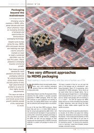
Package Molding<br />
Metal Stack<br />
Copper Pillar<br />
TSV<br />
Copper Pillar<br />
Metal Stack<br />
Package Molding<br />
Fig. 1: WIOMING prototype concept, including WideIO DRAM stacked over logic SoC<br />
16<br />
3 D P a c k a g i n g
I S S U E N ° 2 2 F E B R U A R Y 2 0 1 2<br />
order to pave the way for future products,<br />
using a three-layer <strong>3D</strong>-stack test vehicle.<br />
This three-dies stack integrates a WideIO<br />
compatible DRAM memory stacked over two<br />
WIOMING, a multi-core application processor.<br />
This advanced <strong>3D</strong> prototype is a first proof of<br />
concept of how to efficiently stack memory<br />
on logic and logic on logic (Fig. 1). The overall<br />
project objective is three fold: i) validate and<br />
ramp-up the <strong>3D</strong> technology ii) develop and<br />
validate the <strong>3D</strong> design flow and tools, and iii)<br />
develop the required architectural building<br />
blocks, mainly the Wide IO DRAM interface<br />
and a <strong>3D</strong> asynchronous Network-on-Chip.<br />
CEA-Leti brings its <strong>3D</strong> technology and its<br />
experience in NoC design, integrated in an<br />
existing multi-core processor backbone; ST-<br />
Ericsson brings its knowledge in advanced<br />
DRAM interface and its ability to drive a full<br />
project from application requirements down<br />
to fabrication and test.<br />
YD: At RTI this past December, you<br />
jointly presented the WIOMING circuit<br />
with <strong>3D</strong> Wide IO technology. Could you<br />
describe this circuit and its capabilities?<br />
VG & PV: The WIOMING is made of three<br />
stacked dies, integrating a Wide I/O DRAM<br />
memory stacked on top of two identical<br />
SOC logic dies, which incorporates multiple<br />
processor cores on each die. TSVs (throughsilicon<br />
vias) connect these three dies<br />
together. The ST-Ericsson WIOMING provides<br />
12.8GBytes/s of memory bandwidth, which is<br />
a 50% increase over the latest available dual<br />
channel LPDDR2 solutions at 533MHz, and<br />
at 20% less power. Increasing the DRAM<br />
frequency to 266MHz, moving to dual data<br />
rate (DDR) mode and combining with existing<br />
LPDDR3 technology for lower bandwidth<br />
operations will enable us to provide more than<br />
50GBytes/s for future ST-Ericsson products.<br />
This will provide for unprecedented graphics<br />
and CPU performance on smartphones and<br />
tablets.<br />
The WIOMING circuit also integrates a <strong>3D</strong><br />
asynchronous Network-on-Chip (<strong>3D</strong>-ANoC)<br />
communication infrastructure. The CEA-Leti ’s<br />
<strong>3D</strong>-ANoC communication infrastructure is<br />
fully implemented in the so-called Quasi-<br />
Delay Insensitive asynchronous logic, which<br />
is a very robust class of un-clocked logic that<br />
brings robustness to Process, Voltage and<br />
Temperature. This Globally Asynchronous<br />
Locally Synchronous <strong>3D</strong> architecture does<br />
away with any global timing and clocking<br />
constraints, both in the 2D direction (within<br />
die sub-units) and in the <strong>3D</strong> direction through<br />
Fig. 2: Multi-processor backbone architecture,integrating a WideIO interface and a <strong>3D</strong> NoC<br />
the TSVs. In order to further reduce the<br />
impact of TSV for <strong>3D</strong> NoC connection, the<br />
<strong>3D</strong> NoC integrates asynchronous serial<br />
links. The <strong>3D</strong>-ANoC technology reaches<br />
550MHz maximum operating frequency<br />
in the 2D direction, and 200MHz in the<br />
<strong>3D</strong> direction. Compared to an equivalent<br />
synchronous NoC, the asynchronous NoC<br />
presents a power consumption reduced<br />
by a ratio of four. Regarding multi-core<br />
architecture, the <strong>3D</strong> Network on Chip brings<br />
an efficient packet-based communication<br />
infrastructure to connect the die sub-cores<br />
together, instead of the more traditional onchip<br />
bus interconnect. For testability and<br />
yield purposes, the <strong>3D</strong>-ANoC architecture<br />
also integrates some <strong>3D</strong> DFT (Design<br />
for Test) structures as well as TSV fault<br />
tolerance scheme. The proposed <strong>3D</strong>-ANoC<br />
communication infrastructure allows easy<br />
connection of a large multi-core backbone in<br />
both the 2D and <strong>3D</strong> dimensions (Fig. 2).<br />
Together with the high throughput and low<br />
power Wide IO memory interface, it is then<br />
possible to build a 3-die circuit, efficiently<br />
stacking memory on logic and logic on<br />
logic (Fig. 3). This advanced three-dies<br />
<strong>3D</strong> prototype represents a first proof of<br />
concept that clearly demonstrates how these<br />
technologies can be employed to efficiently<br />
stack memory and logic for future <strong>3D</strong> multiprocessor<br />
architectures.<br />
YD : What products has ST-Ericsson<br />
targeted for this wide IO technology?<br />
VG: ST-Ericsson is preparing the WideIO<br />
technology for their Nova application<br />
processors, as well as the integrated LTE<br />
NovaThor digital base band solutions for<br />
tablets and smartphones. The current<br />
generation of products under development<br />
is based on the JEDEC LPDDR3 memory<br />
standard. To significantly increase memory<br />
bandwidth in the next generation of<br />
products, ST-Ericsson is considering a split<br />
memory architecture which makes use<br />
of a combination of WideIO and LPDDR3<br />
memories. For example, a wide IO memory<br />
could be stacked over a SoC including<br />
application processor, baseband, as well<br />
as wide IO memory controller and LPDDR3<br />
memory controller.<br />
YD: A new JEDEC standard for wide<br />
I/O was announced on January 5,<br />
2012. What are your thoughts on this<br />
announcement?<br />
VG & PV: The WIOMING does implement the<br />
Jedec Wide I/O standard published on January<br />
5, 2012. ST-Ericsson and ST-Microelectronics<br />
were able to release a Wide I/O chip at the<br />
Fig. 3: WIOMING <strong>3D</strong> stack, including WideIO DRAM and two SoC<br />
17
F e b r u a r y 2 0 1 2 I S S U E N ° 2 2<br />
“Increasing the<br />
DRAM frequency to<br />
266MHz, moving<br />
to dual data rate<br />
(DDR) mode and<br />
combining with<br />
existing LPDDR3<br />
technology for<br />
lower bandwidth<br />
operations will<br />
enable us to<br />
provide more than<br />
50GBytes/s for<br />
future ST-Ericsson<br />
products.”<br />
same time the standard specification was published<br />
by Jedec, which reflects the involvement of both<br />
companies in the simultaneous development of the<br />
standard and the device.<br />
YD: You worked in close collaboration with<br />
Cadence to develop new EDA tools. What do<br />
you believe to be the remaining challenges in<br />
design and test for <strong>3D</strong> Integration?<br />
VG & PV: With regard to <strong>3D</strong> CAD tool and design<br />
flow, CEA-Leti and ST-Ericsson worked in close<br />
cooperation with ST-Microelectronics and Cadence.<br />
The <strong>3D</strong> design kit was developed and is maintained<br />
by ST-Microelectronics, with the help of the others.<br />
Cadence provided its latest EDI version, including<br />
a set of <strong>3D</strong> features which extend from early floorplanning<br />
to place and route, as well as timing and<br />
power analysis, taking into account all TSV-related<br />
constraints. Cadence’s tool suite is mature enough<br />
to successfully implement all 2D and <strong>3D</strong> aspects of<br />
such a complex design.<br />
However, one remaining issue is to manage the<br />
format of the logical models used to describe the<br />
overall <strong>3D</strong> stack - in particular with the memory<br />
provider. Different companies using different<br />
design flows interact with each together, which<br />
is a new working model for the digital design and<br />
the signoff of the complete system. Consequently,<br />
there needs to be good cooperation between all<br />
players. Once this cooperation is defined and<br />
agreed, it will enable a complete cross-die design<br />
flow in order to emulate the full system - for<br />
example, but not restricted to, timing, power and<br />
thermal analysis.<br />
Another challenge for <strong>3D</strong> primarily concerns power<br />
and thermal analysis. Some initial <strong>3D</strong> analyses<br />
have been performed, but the results need to be<br />
validated with silicon measurements. For Designfor-Test<br />
(DFT) for <strong>3D</strong>, some classical DFT techniques<br />
such as Boundary Scan have been applied to <strong>3D</strong><br />
signals (WideIO and <strong>3D</strong> NoC) using existing DFT<br />
tools, but with some specific add-on to handle the<br />
JTAG protocol within the <strong>3D</strong> stack. Such <strong>3D</strong> DFT<br />
challenges are currently being studied in the IEEE<br />
<strong>3D</strong>-Test Working Group. Nevertheless, CAD tool<br />
implementations of the IEEE <strong>3D</strong>T-WG proposed<br />
solutions are not yet fully available.<br />
Here’s a table that summarizes which DFT features<br />
have/have not been implemented in the WIOMING:<br />
There are still some test issues to be resolved - in<br />
particular, the diagnosis needs to be reworked for<br />
fast process issue identification during reliability<br />
qualification / yield ramp-up phase / customer<br />
return.<br />
YD: In your opinion, how should the different<br />
players (IDMs, OSATs, Foundries) collaborate to<br />
successfully commercialize wide IO technology?<br />
VG & PV : Only the full engagement of the<br />
OEMs, IDMs and memory suppliers to produce<br />
a commercial product platform will drive the<br />
business model and supply chain requirements<br />
to a workable solution. The consignment models<br />
which are already in place for some products with<br />
integrated KGD memory are the way to go forward,<br />
as it is the only way to make it suitable for the<br />
OSATs, memory suppliers and IDMs. Dedicated<br />
memory test and failure analysis solutions have<br />
to be worked out together in order to enable high<br />
test coverage, quick failure location and low DPPM<br />
in the final product, without generating too much<br />
overhead during the production process.<br />
DFT<br />
Features<br />
DFT<br />
Complexity<br />
ATE<br />
Implementation<br />
complexity<br />
Direct Access Medium High<br />
<strong>3D</strong> interconnections<br />
Stacked Memory<br />
Full coverage @-speed Diagnosis Full coverage Diagnosis<br />
No No No Yes Yes<br />
Embedded<br />
BIST<br />
High<br />
High<br />
Yes Yes No Yes Address fail<br />
Boundary<br />
Scan<br />
Medium<br />
Low<br />
Yes No Yes No Static only<br />
ATPG High Medium<br />
Some commercial solutions and papers available, but yet untested<br />
for <strong>3D</strong> interconnections here while ATPG used on SoC side only<br />
Parametric<br />
No physical access to <strong>3D</strong> IOs =><br />
No individual test measures for DC or AC parameter characterization<br />
IddQ No<br />
www.stericsson.com - www.leti.fr<br />
Vincent Guerin, Senior Digital Design Engineer,<br />
ST-Ericsson<br />
Vincent GUERIN is working for ST-Ericsson since 2009, as technical advisor within<br />
the physical design department. Member of the Technical Staff, he is in charge<br />
of identifying and developing new methodologies to improve Power/Performance/<br />
Area of wireless chips, such as pulse latch bank or advanced CTS techniques. He is<br />
also implicated in the physical implementation of pilot projects and in this context<br />
participates to the development of <strong>3D</strong> ICs.<br />
Prior to joining ST-Ericsson, he worked as CAD Support Engineer for Texas<br />
Instruments and as Field Application Engineer for Magma Design Automation.<br />
Pascal Vivet, Researcher, CEA-Leti, MINATEC<br />
Pascal Vivet received his Master of Electronics from University Joseph Fourier<br />
(UJF), Grenoble in 1994. He accomplished his PhD in 2001 within France Telecom<br />
lab, Grenoble, designing an asynchronous Quasi-Delay-Insensitive microprocessor.<br />
After 4 years within STMicroelectronics, Pascal Vivet has joined CEA-Leti in 2003<br />
in the advanced design department of the Center for Innovation in Micro and<br />
Nanotechnology (MINATEC), Grenoble, France. His main topics of interests are focused<br />
on asynchronous logic, Globally-Asynchronous-Locally-Synchronous design, Networkon-Chip<br />
architectures, Low Power design, high level modeling using SystemC/TLM,<br />
Processor Array architectures, and more recently <strong>3D</strong> design. He has participated to<br />
the design of three main NoC prototypes, the FAUST, ALPIN and MAGALI circuits. He is<br />
currently involved in the development of <strong>3D</strong> prototypes. He is the author or co-author<br />
of more than 40 papers.<br />
18<br />
3 D P a c k a g i n g
IMAGE SENSORS 2012<br />
0.2<br />
0.1<br />
IMAGE SENSORS 2012<br />
FOCUS ON DIGITAL IMAGING<br />
20-22 March, Hotel Russell, London<br />
Keynote Speakers<br />
www.image-sensors.com<br />
0.3<br />
Dr Eric R. Fossum<br />
THAYER SCHOOL OF<br />
ENGINEERING AT<br />
DARTMOUTH, US<br />
Dr Samuel Harvey<br />
Moseley<br />
NASA/GODDARD SPACE<br />
FLIGHT CENTER, US<br />
Dr Nobukazu<br />
Teranishi<br />
PANASONIC<br />
CORPORATION, Japan<br />
Mats Wernersson<br />
SONY ERICSSON, Sweden<br />
0.4<br />
0.5<br />
All readers offered special 15% discount off the conference rate if booked before 6 March!<br />
IntertechPira’s 5th annual Image Sensors programme brings<br />
together both legendary experts and outstanding newcomers from the imaging world.<br />
The spectrum of applications covered is wider than ever before with best in class imaging<br />
technology being profiled from healthcare, aerial, broadcast, mobile communications,<br />
automotive, security, defence, space, astronomy and industrial sectors.<br />
Book online with discount code 3dp or find out more about IS2012 at image-sensors.com<br />
IS12full[186x273].indd 1 30/1/12 17:14:47
F E B R U A R Y 2 0 1 2 I S S U E N ° 2 2<br />
ANALYST CORNER<br />
Market dynamics impact WLCSP<br />
adoption<br />
For connectivity devices, WLCSP became the standard package in 2010, and the<br />
market is poised to continue growing.<br />
Jean-Marc Yannou,<br />
Senior Analyst,<br />
Advanced Packaging,<br />
Yole Développement<br />
Wafer-level chip-scale package (WLCSP)<br />
market growth is expected to climb by<br />
12.6% during the next 5 years, while the<br />
compound annual growth rate (CAGR) for 2010–<br />
2016 appears to be growing much faster for MEMS<br />
and image sensors (at 25%) than for CMOS and<br />
analog ICs (at 7%)—in WLCSP units.<br />
Why? Certain sectors, such as the connectivity<br />
devices used in mobile phones, are nearly 100%<br />
WLCSP now, displacing QFN and BGA packages.<br />
Another reason is that we’re not seeing WLCSPs<br />
being used outside of the mobile world. Very<br />
few are used in PCs or consumer devices, or other<br />
automotive or industrial applications. Growth,<br />
however, is emerging with tablets, which proves that<br />
they are being built to smartphone architectures<br />
rather than PCs.<br />
Certain changes in the mobile phone industry<br />
have had a big impact on WLCSP. Nokia used to<br />
be the world’s OEM leader and biggest champion<br />
of WLCSP, so that’s one reason why its adoption<br />
in ICs failed to grow as quickly as expected during<br />
2010–2011. Second-tier OEMs didn’t take to<br />
WLCSPs; they’re using larger packages that can<br />
be mounted on cheaper assembly lines in China,<br />
rather than WLCSP, which is considered a little<br />
tricky to mount on end-users’ PCBs. In the end, it<br />
always comes down to cost and these second-tier<br />
companies are avoiding making any unnecessary<br />
new investments in equipment.<br />
Who’s leading the way with WLCSP now? Broadcom<br />
shipped 300,000 WLCSP wafers in 2010, which is<br />
a tremendous volume. They needed to work with<br />
five subcontractors—ASE, Nepes, SPIL, STATS<br />
ChipPAC, and now TSMC—because there wasn’t<br />
one who could handle the entire volume.<br />
Where are all of these WLCSPs going? Most notably,<br />
many of Broadcom’s WiFi combo chips are being<br />
used in Apple’s iPhones, iPads, and iPods, as well<br />
as Motorola’s products.<br />
2010-2016 WLCSP unit forecast by end equipment type<br />
We are not seeing WLCSPs being widely used outside of mobile phones and tablets<br />
50 000<br />
45 000<br />
40 000<br />
35 000<br />
30 000<br />
Units<br />
25 000<br />
20 000<br />
15 000<br />
10 000<br />
5000<br />
0<br />
2010<br />
2011 2012 2013 2014 2015 2016<br />
voice phone<br />
smartphones<br />
PMP/MP3<br />
notebooks<br />
feature phones<br />
tablets<br />
set to box<br />
others (medical, automotive...)<br />
(WLCSP Market & Industrial Trends report, January 2012, Yole Développement)<br />
20<br />
3 D P a c k a g i n g
I S S U E N ° 2 2 F e b r u a r y 2 0 1 2<br />
Pad<br />
Redistribution<br />
Copper pillar<br />
The average WLCSP device size<br />
is growing larger: the largest<br />
WLCSP IC on the market, the<br />
Fujitsu MB38C311A, is a 309<br />
I/O 50mm² large WLCSP chip<br />
with PMU, and audio interface<br />
functions (Courtesy of<br />
System Plus Consulting)<br />
These connectivity chips are manufactured in<br />
WLCSP form, but don’t ship this way to the OEMs.<br />
They’re first sent to a module maker, who then<br />
creates a module like an internal piece of PCB,<br />
onto which the WLCSP device is meshed along<br />
with other discrete passive devices. At this point it<br />
becomes difficult to say whether these devices are<br />
actually WLCSP or flip chip. Since they’re bumped<br />
on an internal substrate prior to shipping to the<br />
OEM, they can be considered flip chip. But the<br />
pitch between two consecutive bumps is closer to<br />
WLCSP pitch than flip chip pitch. It actually falls<br />
halfway between WLCSP and flip chip for the most<br />
advanced connectivity modules—because the WLCSP<br />
connectivity die pitch is shrinking (down to 250µm<br />
for the most advanced ones). But it’s excluded from<br />
the flip chip family due to its larger pitch.<br />
In terms of WLCSP adoption, we were surprised<br />
to discover that this package hasn’t been adopted<br />
for applications outside of smartphones, except<br />
for tablets. It’s an inexpensive type of package<br />
and the reason it isn’t experiencing wide adoption<br />
appears to center on the small pitch to the PCB.<br />
Other applications require a larger pitch, so now<br />
the question is: Will we see WLCSP in any other<br />
sectors anytime soon? It’s doubtful—at least in the<br />
near future.<br />
units has grown considerably during the past 3<br />
years. We’re now frequently finding 30mm 2 or<br />
larger devices packaged with WLCSP, which wasn’t<br />
previously the case. These connectivity chips<br />
are mounted on modules, so they may not be<br />
representative of all of the other devices, which<br />
are generally below 10mm 2 . The average die size<br />
with WLCSP is becoming larger with technology<br />
improvements.<br />
For reliability, it’s good to consider smaller devices.<br />
And the move from CMOS 45nm to 28nm should<br />
enable that. But it also means that many devices<br />
will become I/O limited. With the current WLCSP<br />
pitch, there won’t be enough area on the die to<br />
place all of the bumps needed to reach all of the<br />
external interfaces and the PCB. So WLCSP will no<br />
longer be an option for devices that would be I/O<br />
limited. Options are to use fan-out WLCSP or chip<br />
embedding that’s already at 28nm or go back to a<br />
previous package type, namely BGA, flip chip or QFN.<br />
With the adoption of CMOS 28nm, if some of the<br />
fan-in WLCSP technology shifts to fan-out, it may<br />
change the competitive landscape—that’s why<br />
some WLCSP companies, including Teramikros and<br />
FlipChip International, are already investing in chip<br />
embedding technologies.<br />
“The average die<br />
size of WLCSP<br />
packaged units<br />
has grown<br />
considerably<br />
during the past<br />
3 years,” says<br />
Jean-Marc Yannou.<br />
Moving forward, the biggest question is what will<br />
happen to WLCSP and the connectivity devices<br />
as CMOS technology migrates to 28nm from the<br />
current 45nm node. One issue is reliability of<br />
WLCSP. With the move to the next CMOS node<br />
devices can be made smaller, and small devices<br />
are known to be generally more reliable than large<br />
devices with WLCSP. As a matter of fact, WLCSP<br />
usually applies to the smallest of devices, even<br />
though the average die size of WLCSP packaged<br />
Also expect to witness more WLCSP manufacturing<br />
in China. In 2010, 8% of worldwide WLCSP capacity<br />
came from China, which was the same amount<br />
produced in the US and Europe. But China’s share<br />
appears to be growing, with Chinese-based JCAP<br />
expanding its 300mm wafer capacity and Nantong<br />
Fujitsu planning to open a factory for full turnkey<br />
services.<br />
www.yole.fr<br />
Jean-Marc Yannou joined Yole<br />
Développement in 2009 as a market<br />
analyst and project manager for<br />
Advanced Semiconductor Packaging.<br />
Before, he occupied various positions<br />
in the semiconductor industry for<br />
15 years. He worked for Texas<br />
Instruments in test and product<br />
engineering and for Philips (then NXP<br />
semiconductor) where he served as<br />
Innovation Manager for System-inpackage<br />
technologies.<br />
3 D P a c k a g i n g<br />
21
F e b r u a r y 2 0 1 2 I S S U E N ° 2 2<br />
WLCSP market trends to watch<br />
in 2012<br />
2012 should be a robust year for the WLCSP market, with interesting supply chain<br />
trends emerging.<br />
Lionel Cadix,<br />
Market & Technology<br />
Analyst,<br />
Advanced Packaging,<br />
Yole Développement<br />
There are essentially two wafer-level chip-scale<br />
package (WLCSP) supply chains: One for fan-in<br />
WLCSPs, which are considered “regular” WLCSPs<br />
without through silicon vias (TSVs), and a separate<br />
one for <strong>3D</strong> WLCSPs, which are WLCSP packages<br />
with multiple levels of dies or lids and TSVs. <strong>3D</strong><br />
WLCSP applies to MEMS and to many CMOS image<br />
sensors.<br />
In the <strong>3D</strong> WLCSP platform, 80% of capacity is split<br />
60/20 between wafer-level packaging houses and<br />
integrated device manufacturers (IDMs).<br />
The top three device categories for WLCSPs are<br />
analog and mixed-signal, wireless connectivity,<br />
and image sensors. The top three device types<br />
include a Bluetooth/WiFi/FM combo, CMOS image<br />
sensors, and DC/DC converters.<br />
~12% for 2010-2016, despite decreasing prices.<br />
Growth, however, won’t occur equally across all<br />
device types—expect a low CAGR for ICs, and a<br />
high one for MEMS.<br />
At least 25 billion WLCSP devices are targeted<br />
for shipment in 2012, driven primarily by wireless<br />
connectivity for mobile/telecom applications,<br />
followed by CMOS image sensors.<br />
The use of fan-in WLCSP for connectivity devices<br />
in handsets is becoming increasingly standardized;<br />
in 2012 it will approach 100%. Biggest customer?<br />
Broadcom. Other solutions used for the same<br />
application, such as QFN or BGA solutions, are now<br />
being sidelined by fan-in WLCSP.<br />
Trends<br />
There are two key WLCSP trends worth mentioning.<br />
“The top three<br />
device categories<br />
for WLCSPs are<br />
analog and mixedsignal,<br />
wireless<br />
connectivity, and<br />
image sensors. The<br />
top three device<br />
types include a<br />
Bluetooth/WiFi/<br />
FM combo, CMOS<br />
image sensors,<br />
and DC/DC<br />
converters,”<br />
explains Lionel Cadix.<br />
Market outlook for 2012<br />
The global WLCSP market value, including wafer<br />
level service, die level service and test, exceeded<br />
B$1.5 in 2011, with an expected CAGR value of<br />
%<br />
60<br />
50<br />
40<br />
30<br />
20<br />
10<br />
0<br />
MEMS, sensors and BAW<br />
track pad controller<br />
USB controller<br />
CMOS image sensors<br />
GPS<br />
magnetometer<br />
MOSFETs<br />
touch screen controller<br />
Audio/video codec<br />
microcontroller<br />
First, IDMs want to reduce their dependence<br />
on packaging subcontractors who didn’t invest<br />
enough in 8 and 12 inch. capacities during the<br />
2008-2009 economic downturn. As a result, IDMs<br />
are creating internal capacity for fan-in WLCSP.<br />
Fan-in WLCSP 2010-2016 unit CAGR (%) by device type<br />
BT+WiFi+FM combo<br />
logic gates<br />
Audio power amplifiers + video drivers<br />
temperature sensor<br />
others (medical, automotive, FPGA,<br />
ctrl…)<br />
PMU/PMIC<br />
ESD/EMI IPD<br />
DC/DC converter / LDO<br />
Amplifier / switch / RF power detector /<br />
voice coil motor driver IC, …<br />
LED driver Ics<br />
EEPROM/flash<br />
bluetooth+FM<br />
(WLCSP Market & Industrial Trends report, January 2012, Yole Développement)<br />
22<br />
3 D P a c k a g i n g
I S S U E N ° 2 2 F e b r u a r y 2 0 1 2<br />
Texas Instruments, for example, is one IDM with<br />
significant WLCSP production capacity. TI invested<br />
heavily in 300mm bumping at their Clark facility in<br />
the Philippines in 2010.<br />
3000<br />
WLCSP total market value (M$)<br />
Second, with cost pressure clearly threatening the<br />
integrated position of the OSATs within the WLCSP<br />
space, some wafer bumping houses are considering<br />
climbing the value chain to provide full turn-key<br />
services to their customers—by developing wafer<br />
test and back-end steps.<br />
Company highlights<br />
M$<br />
2500<br />
2000<br />
1500<br />
CAGR ~ 12%<br />
As far as individual companies making bold moves<br />
in the WLCSP market, the more noteworthy<br />
highlights include:<br />
1000<br />
TI invested significantly in 300 mm bumping for<br />
flip chip and WLCSP at their Clark facility in 2010.<br />
500<br />
STMicroelectronics is currently building a midend<br />
facility in Singapore for flip chip bumping,<br />
fan-in WLCSP, FOWLP, and 2.5D glass and silicon<br />
interposer substrates.<br />
TSMC stepped up with their first investment in fanin<br />
WLCSP. Their 300mm fab was built under the<br />
name “Xintec/TSMC,” but since 2011, the Hsinchu,<br />
Taiwan-based line has been fully operated by TSMC<br />
and is serving customers with full turn-key fan-in<br />
WLCSP services—including test and back-end—on<br />
300mm wafers.<br />
In Japan, Casio Micronics and Tera Probe formed a<br />
new company called Teramikros, which is the first<br />
in the world to attempt to become a pure-play fanin<br />
WLCSP contract manufacturing service provider.<br />
Teramikros is now licensing its fan-in technology<br />
and qualifying a Chinese OSAT, Nantong Fujitsu,<br />
for Q2 2012.<br />
STATS ChipPAC completed expansion of its 300mm<br />
operations in Taiwan, taking additional capacity<br />
online in 2011. This was the most significant OSAT<br />
investment in WLCSP during the past 3 years.<br />
And, JCAP in China is expanding its 300mm fanin<br />
capacities and moving to <strong>3D</strong> WLCSP services,<br />
including via-last TSV for MEMS and CMOS image<br />
sensor packaging on 200mm wafers.<br />
Manufacturing locations<br />
If you guessed that the main manufacturing<br />
location for WLCSP is still Taiwan, you’re right,<br />
with 39% of all processed wafers originating there,<br />
followed by Japan and Europe.<br />
For fan-in WLCSP, the big players are Taiwan-based<br />
ASE in 200mm wafers and SPIL in 300mm wafers.<br />
0<br />
2010 2011 2012 2013 2014 2015 2016<br />
(WLCSP Market & Industrial Trends report, January 2012, Yole Développement)<br />
For <strong>3D</strong> WLCSP, the top players are Taiwan-based<br />
Xintec in 200mm wafers (61% of processed wafers)<br />
and France-based STMicroelectronics in 300mm<br />
wafers (68%).<br />
Currently, there’s an emerging manufacturing<br />
shift to China. What’s behind it? In 2010, most<br />
WLCSP fab capacity was booked due to higherthan-expected<br />
demand from IC companies. OSATs<br />
and wafer bumping houses didn’t invest in enough<br />
extra capacity, which led to price tension in the<br />
market and created a situation in which some<br />
analog and mixed-signal companies couldn’t ramp<br />
up new products in WLCSP because of OSATs’ high<br />
pricing for full turn-key WLCSP services. Afterward,<br />
several companies shifted to Chinese WLCSP<br />
players to find extra capacity at competitive prices.<br />
Pursuit of the fan-in WLCSP market<br />
Company to pay close attention to in the WLCSP<br />
space include: Powertech Technology Inc. (PTI).<br />
Taiwan-based PTI is on its way to becoming<br />
another big challenger in the WLCSP space. PTI is<br />
building a mid-end factory to supply open-contract<br />
manufacturing services based on flip chips with<br />
copper pillars/fan-in WLCSPs/<strong>3D</strong>ICs and TSVs.<br />
2012 will certainly be interesting for this company—<br />
and the entire market!<br />
www.yole.fr<br />
Lionel Cadix joined Yole<br />
Développement after the completion<br />
of several projects linked to the<br />
characterization and modeling of<br />
high density TSV and <strong>3D</strong>IC chip<br />
stacking in collaboration with CEA-<br />
Leti and STMicroelectronics during<br />
his PhD. He is author of several<br />
publications and 8 patents in the<br />
field of <strong>3D</strong> Integration.<br />
3 D P a c k a g i n g<br />
23
F e b r u a r y 2 0 1 2 I S S U E N ° 2 2<br />
Moving <strong>3D</strong> IC forward with the<br />
standardization of wide IO DRAM<br />
<strong>3D</strong> IC technology has taken a giant step forward with the recent announcement<br />
by JEDEC that it has issued standard JESD229 for Wide I/O mobile DRAM.<br />
Participants in the effort included many of the major global players including<br />
Samsung, Elpida, Hynix, Micron, Qualcomm, Nokia, ST Ericsson, TI, Intel, AMD,<br />
Apple and others.<br />
Dr Phil Garrou,<br />
Senior Analyst,<br />
Advanced Packaging,<br />
Yole Développement<br />
JEDEC JESD229 for Wide I/O mobile DRAM<br />
The purpose of this standard is to define the<br />
minimum set of requirements for JEDEC compliant,<br />
1 GBb through 32 GbB DRAM devices with four,<br />
128b wide channels using direct chip-to-chip attach<br />
methods between 1 to 4 memory devices and a<br />
controller device. The standard defines the Wide<br />
I/O specification including features, functionality,<br />
AC and DC characteristics, packages, and pin<br />
signal assignments.<br />
The 512-bit memory interface has four independent<br />
128 bits wide channels each operating at clock<br />
speeds to 266 MHz resulting in a total bandwidth<br />
of 17 GBb/s for wide I/O SDRAMs (4.26 GBb/s/<br />
channel). The specification supports as many<br />
as four memory banks per channel, allowing die<br />
stacking of up to four wide I/O SDRAM die. The<br />
specification calls for 1.2V signal levels.<br />
Wide IO electrical and LMI (Logic Memory Interface)<br />
specifications are shown below:<br />
• Large bus interface (512 bits) at low frequency<br />
(200 MHz) in SDR<br />
• 4 independent and fully asynchronous channels<br />
• BW = 12.8 GBps (200 Mbps per pin)<br />
• VDD1 = 1.8V, VDD2 = 1.2V, VDDQ = 1.2V<br />
• Low Power Features: PASR, Auto TCSR<br />
• Balls allocated for future DDR extension<br />
• Total number of balls including supply: 1200<br />
(193/ch signal)<br />
• Density: up to 32 Gbit monolithic<br />
• Up to 4 DRAM dice stacked on top of the mobile<br />
processor<br />
5.27 mm<br />
• Boundary Scan<br />
• IO physical location<br />
– Each channel has 6 rows and 50 columns<br />
– 40µOm min pad/bump/TSV pitch<br />
JESD229 does not standardize the bonding<br />
configuration between the memory and logic chips<br />
– i.e. F2F, B2F, side-by-side with interposer, or<br />
stacked memory on top of logic. JESD229 may be<br />
downloaded on JEDEC website (ww.jedec.org).<br />
The next generation of this Wide I/O specification,<br />
already underway, promises to deliver eight times<br />
the performance and support 2.5D assembly.<br />
Wide IO Required for Future<br />
Smartphones and Tablets<br />
Sophie Dumas, from the CTO office of ST Ericsson<br />
and Chairman of the JEDEC subcommittee for Low<br />
Power Memories, indicates that Wide I/O mobile<br />
DRAM using <strong>3D</strong> stacking with TSV will provide<br />
“double the bandwidth at the same power, or can<br />
cut power in half at the same bandwidth” and<br />
compared to LPDDR2 and LPDDR3 it is particularly<br />
well suited for applications requiring increased<br />
memory bandwidth up to 17GB/second, such as<br />
<strong>3D</strong> gaming, high resolution displays (1080p H264<br />
video, pico projectors), and user multitasking»<br />
Dumas continues that “…display resolution will<br />
double for smartphones and quadruple for tablets<br />
in the near future, both requiring significant<br />
increases in memory bandwidth”.<br />
Dumas and the JEDEC committee expect Wide IO<br />
to be in mass production by early 2014.<br />
nns<br />
0.54 mm<br />
ADDR<br />
CMD<br />
DQ<br />
DQS/DM<br />
6 column<br />
spacing<br />
2 ~ 3<br />
row spacing<br />
Wide IO electrical and LMI (Logic Memory Interface) specifications (Courtesy of JEDEC)<br />
24<br />
3 D P a c k a g i n g
I S S U E N ° 2 2 F e b r u a r y 2 0 1 2<br />
2011<br />
LPDDR2<br />
3.2 GBps<br />
2012<br />
LPDDR2<br />
4.3 GBps<br />
2013<br />
LPDDR3<br />
6.4 GBps<br />
2014<br />
WideI0<br />
12.8 GBps<br />
Expected Device<br />
Mass Production<br />
Mobile Memory Std Wide IO LPDDR3 LPDDR2<br />
Data IO width (bits) 512 32 32<br />
Max data transfer rate per 10 (Mb/s) 200 1600 800,1066<br />
Max data transfer rate per device (Gb/s) 12.8 6.4 3.2, 4.3<br />
Relative power comsumption<br />
Wide IO adoption already underway<br />
For mobile applications Wide IO DRAM die is stacked on top of<br />
the mobile application processor. Details on such structures have<br />
recently been described in the ST Ericsson, Cadence, CEA Leti<br />
program known as Wioming.<br />
In early 2011 Samsung announced wide IO DRAM and the goal of<br />
providing 20 nm, 4Gb wide I/O mobile DRAM sometime in 2013..<br />
In December 2011, Elpida announced sample shipments of 4Gbit<br />
Wide-IO, announcing volume production for these devices in 2012.<br />
At the recent IC Packaging Technology Expo at NEPCON Japan<br />
Renesas announced that they will apply TSV technology to its<br />
mobile SoCs so that they will support Wide I/O DRAM starting with<br />
mobile phone products. The DRAM will be stacked on the back of<br />
the SoC via 1,200 microbumps. The company plans to contract out<br />
the production of advanced SoCs to a silicon foundry as well as the<br />
production of TSV.<br />
Early in 2011 Micron released details on its hybrid memory cube<br />
(HMC) technology and the consortium they created with Samsung to<br />
collaborate on the implementation of an open interface specification<br />
for the HMC technology.<br />
Open-Silicon, a fabless ASIC designer is developing the controller<br />
IP for HMC based on their Interlaken controller IP ( a high-speed,<br />
chip-to-chip interface protocol). Based on Micron’s specifications,<br />
the logic controller layer of HMC, complete with TSV, will be<br />
manufactured by IBM in East Fishkill NY, using 32nm, high-k metal<br />
gate process technology. Micron will fabricate the DRAM arrays<br />
based on their 3x nm process in their fabs. Micron will also assemble<br />
their memory layers and the IBM logic control layer at their R&D<br />
production line in Boise, Idaho.<br />
For those interested in following the progress of <strong>3D</strong> standardization,<br />
Wiki Sematech is tracking and continually updating here<br />
(http://wiki.sematech.org/<strong>3D</strong>-Standards-List).<br />
www.yole.fr<br />
Phil Garrou joined Yole Développement forces as senior technical advisor<br />
in the fields of advanced packaging. Phil as more than 20 years extensive<br />
experiences in the semiconductor industry where he mainly served as global<br />
marketing manager for DOW Chemical’s BCB polymer business.<br />
3 D P a c k a g i n g<br />
25
F e b r u a r y 2 0 1 2 I S S U E N ° 2 2<br />
W h a t ’ s I n s i d e ?<br />
OmniVision’s VGA wafer-level<br />
camera<br />
Whether it’s for the main camera of low-cost phones or the front-facing camera<br />
of high-end phones, low-cost, low-resolution camera modules are extremely<br />
important.<br />
Wafer-level cameras<br />
In order to manufacture low-cost camera modules,<br />
the main cost drivers -- the image sensor, the<br />
optical module and the fixture used to assemble the<br />
module to the phone board -- have to be reduced to<br />
a strict minimum.<br />
The image sensors lend themselves rather well<br />
to low-cost manufacturing due to their waferlevel<br />
manufacturing approach. With this approach<br />
it is possible to manufacture optical lenses at<br />
the wafer-level, thus creating a very low-cost<br />
wafer-level optical module (or wafer-level optics,<br />
WLOptics). Another benefit of WLOptics is their<br />
reflow-compatible materials. By eliminating the<br />
plastic lenses used in standard optical modules, the<br />
camera modules become compatible with reflow<br />
soldering, and thus can be integrated at the same<br />
time as the other surface mount components on the<br />
phone board.<br />
One way to optimize this reflow compatibility is to<br />
package the image sensor at the wafer-level by<br />
redistributing the pads to the back side. This also<br />
reduces the camera module area to the image<br />
sensor area.<br />
OmniVision CameraCube<br />
The OVM7692 is a VGA reflowable camera module<br />
which integrates a Wafer-Level Packaged CMOS<br />
Image Sensor and Wafer-Level Optics. The camera<br />
module is provided in a 2.8 x 3.2 x 2.5 mm 25-pin<br />
package, and integrates a 1.75µm pixel CMOS Image<br />
Sensor (CIS), ref. OV289AA from OmniVision, which<br />
is manufactured by TSMC using a CMOS technology<br />
with a 0.11µm process.<br />
Glass<br />
wafer #2<br />
with lens #1<br />
and aperture<br />
Glass<br />
wafer #3<br />
(Spacer)<br />
Glass<br />
wafer #4<br />
with lens #2<br />
Glass<br />
wafer #5<br />
(Carrier wafer)<br />
CIS<br />
Glass wafer #1<br />
with IR filter<br />
Solder ball<br />
Wafer-level optics<br />
OmniVision OVM7692 cross-section<br />
(Courtesy of System Plus Consulting)<br />
A pioneer of the CMOS Image Sensor industry,<br />
OmniVision released its latest wafer level camera,<br />
the OVM7692, in 2010.<br />
The wafer-level optical module of the OVM7692<br />
is currently outsourced to VisEra Technologies in<br />
Taiwan. VisEra was founded in December 2003 as<br />
a joint venture between TSMC and OmniVision. On<br />
June 30, 2011, OmniVision paid $45M for VisEra’s<br />
WLOptics manufacturing operations, and expects<br />
to close the transaction in the second quarter of<br />
2012. According to OmniVision, this transaction<br />
will allow for streamlining the production process,<br />
consolidating the supply chain, expanding the<br />
production capacity and reducing the cost.<br />
Glass wafer #1<br />
Glass wafer #2<br />
Lens #1<br />
Lens #2<br />
Glass<br />
wafer<br />
#3<br />
Glass wafer #4<br />
OmniVision OVM7692 CameraCubeChip<br />
(Courtesy of System Plus Consulting)<br />
OVM7692 Wafer-level optics cross-section<br />
(Courtesy of System Plus Consulting)<br />
26 3 D P a c k a g i n g
I S S U E N ° 2 2 F E B R U A R Y 2 0 1 2<br />
The WLOptics of the OmniVision CameraCube<br />
consists of an assembly of four glass wafers.<br />
The first glass wafer, on top of the module, holds<br />
an IR filter (consisting of layers of Niobium oxide<br />
sandwiched with layers of Silicon oxide). The<br />
second glass wafer holds the first lens. Next up is<br />
a spacer glass wafer, etched by powder blasting,<br />
which separates the second glass wafer from the<br />
fourth glass wafer -- which holds the second lens.<br />
The lenses are made with a UV curable polymer<br />
and are manufactured with a replication process.<br />
A plastic tool (likely Polydimethylsiloxane --PDMS<br />
silicone) molded into a master is used to imprint the<br />
polymer lenses. Each master can be used to make<br />
a large number of PDMS tools, and each PDMS tool<br />
can be used to imprint a large number of lenses.<br />
Wafer-level packaging<br />
The CMOS Image Sensor (CIS) is Wafer-Level<br />
Packaged (WLP) by Xintec, using a ShellCase RT<br />
process.<br />
Xintec obtained a license for the ShellCase CSP<br />
technology from ShellCase Ltd. in 2000 (Tessera<br />
has since acquired ShellCase Ltd. and now licenses<br />
the ShellCase technology to Xintec). The ShellCase<br />
process consists of a redistribution of the CIS pads<br />
to the back side through the edge of the die, using<br />
a “T-contact”.<br />
The packaging process begins with the bonding<br />
of a glass carrier substrate to the CIS wafer.<br />
Strengthened by its carrier substrate, the CIS wafer<br />
Black<br />
coating<br />
T-contact<br />
Silicone<br />
epoxy<br />
OVM7692 ShellCase CIS WLP cross-section<br />
(Courtesy of System Plus Consulting)<br />
can be thinned down to 130µm, and vias can be<br />
etched all around each CIS die. These vias are then<br />
filled with a conductive aluminum layer. Finally, a<br />
protective encapsulation is created and solder balls<br />
are produced.<br />
Cost structure<br />
Glass Carrier wafer<br />
Metal layer<br />
(Silver)<br />
Silicone epoxy<br />
Cavity<br />
Lead<br />
CMOS Image Sensor<br />
Solder<br />
bump<br />
Wafer-level manufacturing of all camera module<br />
elements results in a significant reduction of the<br />
production cost – in fact, the OmniVision OVM7692’s<br />
total production cost is estimated to be under $1.<br />
Compared to standard camera modules where the<br />
cost is equally distributed between the three main<br />
cost drivers, the wafer-level camera module cost<br />
is especially impacted by the image sensor, which<br />
equates to about 50% of the total manufacturing<br />
cost.<br />
Romain Fraux<br />
System Plus Consulting<br />
Romain Fraux,<br />
Electronics Cost<br />
Engineer,<br />
System Plus<br />
Consulting<br />
Romain Fraux is<br />
Project Manager<br />
for Reverse Costing<br />
analyses at System Plus Consulting.<br />
Since 2006, Romain is in charge of<br />
costing analyses of MEMS devices,<br />
Integrated Circuit and electronics<br />
boards. He has significant experience<br />
in the modeling of the manufacturing<br />
costs of electronics components.<br />
Romain has a BEng from Heriot-Watt<br />
University of Edinburgh, Scotland and<br />
a master’s degree in Microelectronics<br />
from the University of Nantes, France.<br />
OVM7692 camera module cost<br />
breakdown<br />
Camera Module<br />
100%<br />
90%<br />
80%<br />
70%<br />
60%<br />
Final test + Scrap<br />
(Omnivision)<br />
7%<br />
WL-Optic +<br />
Assembly (VisEra)<br />
25%<br />
CIS ShellCase<br />
WLP (Xintec)<br />
19%<br />
Glass<br />
wafer #1<br />
Glass<br />
wafer #2<br />
Glass<br />
wafer<br />
#3<br />
Lens #1<br />
IR filter<br />
AP layer<br />
Wafer-level<br />
Optics<br />
50%<br />
Lens #2<br />
40%<br />
Glass<br />
wafer<br />
#4<br />
Black<br />
coating<br />
30%<br />
20%<br />
CIS Manufacturing<br />
(TSMC)<br />
49%<br />
CMOS Image<br />
Sensor<br />
Glass<br />
Wafer #5<br />
(carrier wafer)<br />
Imaging Area<br />
with micro-lenses<br />
Cavity<br />
T-Contact<br />
Wafer-level<br />
Packaging<br />
10%<br />
0%<br />
OVM7692 structure & cost breakdown (Courtesy of System Plus Consulting)<br />
3 D P a c k a g i n g<br />
27
2012 IEEE<br />
IntErnatIonal IntErconnEct<br />
tEchnology confErEncE<br />
IITC<br />
Innovations In Interconnections<br />
The 15th annual IITC, sponsored by the IEEE Electron Devices<br />
Society, is the semiconductor industry’s premier conference for<br />
interconnect technology. It provides a forum for professionals<br />
from industry, academia and national laboratories in<br />
semiconductor processing, advanced materials, equipment<br />
development, and interconnect systems to present and discuss<br />
exciting new science and technology.<br />
Keynote presenters and invited speakers include:<br />
Mike Mayberry, Vice President of Research, Intel Corp<br />
Bill Dally, Chief Scientist, nVIDIA<br />
Subu Iyer, IBM Fellow responsible for <strong>3D</strong> IC<br />
Michael van Buskirk, CTO of Adesto/former CTO of Spansion<br />
Dan Edelstein, IBM Fellow responsible for BEOL<br />
Axel Preusse, Fellow at GLOBALFOUNDRIES<br />
Jean Marc-Yannou, Analyst focusing on <strong>3D</strong>, Yolé Development<br />
for complete conference and<br />
registration information for<br />
IItc 2012 visit:<br />
http://www.his.com/~iitc/<br />
DoublEtrEE hotEl<br />
San JoSE, ca<br />
JunE 3 – 6, 2012<br />
The northern California venue<br />
is one of three international<br />
locations for this important<br />
technology conference, which<br />
rotates among them annually.<br />
Short courSE<br />
JunE 3, 2012<br />
a one-day short course<br />
on leading-edge<br />
interconnect technology<br />
and emerging materials.<br />
ExhIbItS &<br />
SupplIEr<br />
SEmInarS<br />
new products,<br />
processes,<br />
and materials<br />
will be exhibited<br />
at the conference<br />
and supplier<br />
seminars will be<br />
held in the evenings.<br />
poStEr<br />
SESSIon:<br />
featuring papers<br />
from young Engineers<br />
& Students<br />
IItc tEchnIcal<br />
program<br />
materials &<br />
unit processes<br />
process Integration<br />
characterization<br />
reliability<br />
chip-package<br />
Interaction (cpI)<br />
<strong>3D</strong> Integration<br />
novel Systems<br />
& packaging<br />
novel materials<br />
& concepts,<br />
back-End memories<br />
& mEmS<br />
fine grain <strong>3D</strong><br />
contacts & local<br />
Interconnects<br />
Interconnects<br />
for biological<br />
applications<br />
networks-on-chip<br />
circuits for<br />
high-Speed &<br />
low-power<br />
Signaling<br />
II043 IITC 2012-Yole Media Partnership Ad Dev & Mat.indd 1<br />
2/2/12 11:31 AM
F E B R U A R Y 2 0 1 2 I S S U E N ° 2 2<br />
How can you capture 60%<br />
and over the LED cost?<br />
LED Packaging<br />
2011 edition<br />
Discover the NEW report on<br />
i-<strong>Micronews</strong>.com/reports<br />
About Yole Développement<br />
Beginning in 1998 with Yole Développement, we have grown to become a group of companies providing market research, technology analysis,<br />
strategy consulting, media in addition to fi nance services. With a solid focus on emerging applications using silicon and/or micro manufacturing<br />
Yole Développement group has expanded to include more than 40 associates worldwide covering MEMS, MedTech, Advanced Packaging, Compound<br />
Semiconductors, Power Electronics, LED, and Photovoltaics. The group supports companies, investors and R&D organizations worldwide to help<br />
them understand markets and follow technology trends to develop their business.<br />
CUSTOM STUDIES<br />
• Market data, market research and marketing analysis<br />
• Technology analysis<br />
• Reverse engineering and reverse costing<br />
• Strategy consulting<br />
• Corporate Finance Advisory (M&A and fund raising)<br />
MEDIA<br />
• Critical news, Bi-weekly: <strong>Micronews</strong>, the magazine<br />
• In-depth analysis & Quarterly Technology Magazines: MEMS Trends – <strong>3D</strong> Packaging – iLED – Power Dev’<br />
• Online disruptive technologies website: www.i-micronews.com<br />
• Exclusive and editorial webcasts<br />
• Live event with Market Briefings<br />
CONTACTS<br />
For more information about:<br />
• Services : Jean-Christophe Eloy (eloy@yole.fr)<br />
• Reports: David Jourdan (jourdan@yole.fr)<br />
• Media : Sandrine Leroy (leroy@yole.fr)<br />
TECHNOLOGY & MARKET REPORTS<br />
• Collection of reports<br />
• Players & market databases<br />
• Manufacturing cost simulation tools<br />
• Component reverse engineering & costing analysis<br />
More information on www.yole.fr<br />
Editorial Staff<br />
Managing Editor: Jean-Christophe Eloy - Editor in chief: Jean-Marc Yannou - Editors: Jérôme Baron,<br />
Lionel Cadix, Phil Garrou, Sally Cole Johnson - Media & Communication Manager: Sandrine Leroy -<br />
Media & Communication Coordinator: Camille Favre - Production: atelier JBBOX<br />
29 3 D P a c k a g i n g